Transcription
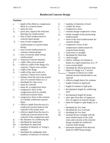
51Composite Steel–Concrete Structures51.1 IntroductionHistory Applications Case Studies51.2 Composite Construction Systems for BuildingsComposite Floor Systems Composite Beams and Girders Long-Span Flooring Systems Composite Column Systems51.3 Material PropertiesMild Structural Steel High-Strength Steel UnconfinedConcrete Confined Concrete Reinforcing Steel ProfiledSteel Sheeting Shear Connectors51.4 Design PhilosophyLimit States Design51.5 Composite SlabsServiceability Strength Ductility51.6 Simply Supported BeamsServiceability Strength Ductility51.7 Continuous BeamsServiceability Strength Ductility51.8 Composite ColumnsBrian UyThe University of New South Wales,AustraliaJ.Y. Richard LiewNational University of SingaporeEurocode 4 AISC-LRFD Australian Standards AS 3600 andAS 410051.9 Lateral Load Resisting SystemsCore Braced Systems Moment–Truss Systems Outrigger andBelt Truss Systems Frame Tube Systems Steel–ConcreteComposite Systems51.1 IntroductionHistoryComposite construction as we know it today was first used in both a building and a bridge in the U.S.over a century ago. The first forms of composite structures incorporated the use of steel and concretefor flexural members, and the issue of longitudinal slip between these elements was soon identified [1].Composite steel–concrete beams are the earliest form of the composite construction method. In theU.S. a patent by an American engineer was developed for the shear connectors at the top flange of auniversal steel section to prevent longitudinal slip. This was the beginning of the development of fullycomposite systems in steel and concrete.Concrete-encased steel sections were initially developed in order to overcome the problem of fireresistance and to ensure that the stability of the steel section was maintained throughout loading. Thesteel section and concrete act compositely to resist axial force and bending moments. 2003 by CRC Press LLC
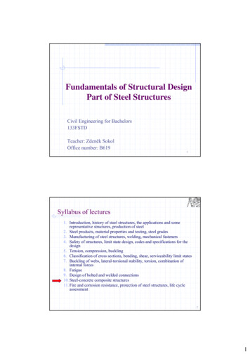
51-2The Civil Engineering Handbook, Second EditionComposite tubular columns were developed because they provided permanent and integral formworkfor a compression member and were instrumental in reducing construction times and consequently costs.They reduce the requirement of lateral reinforcement and costly tying, as well as providing easierconnection to steel universal beams of a steel-framed structure.Composite slabs have been introduced recently to consider the increase in strength that can be achievedif the profiled steel sheeting is taken into account in strength calculations. Composite slabs providepermanent and integral reinforcement, which eliminates the need for placing and stripping of plywoodand timber formwork.More recently, composite slab and beam systems have been developed for reinforced concrete framedconstruction; this provides advantages similar to those attributed to composite slabs for reinforcedconcrete slab and beam systems. These advantages include reduced construction time due to eliminationof formwork, and elimination of excessive amounts of reinforcing steel. This subsequently reduces thespan-to-depth ratios of typical beams and also reduces labor costs.In this chapter, a thorough review is given of research into composite construction, including beams,columns, and profiled composite slabs. Furthermore, design methods are herein summarized for variouspertinent failure modes.ApplicationsComposite construction has been mainly applied to bridges and multistory buildings, with the moretraditional forms of composite beams and composite columns. This section will look at the variousapplications of composite construction to both bridges and buildings.BridgesComposite construction with bridges allows the designer to take full advantage of the steel section intension by shifting the compression force into the concrete slab in sagging bending. This is made possiblethrough the transfer of longitudinal shear force through traditional headed-stud shear connectors.Headed-stud shear connectors not only provide the transfer of shear force, but also help to assist lateralstability of the section. The top flange of the steel section is essentially fully laterally restrained by thepresence of shear connectors at very close spacing, as illustrated in Fig. 51.1.BuildingsIn steel-framed buildings throughout the world, composite floors are essentially the status quo in orderto achieve an economic structure. This is for quite a few reasons. First, composite slabs allow reducedconstruction time by eliminating the need for propping and falsework in the slab-pouring phase. Furthermore, composite beams are economical, as they reduce the structural depth of the floor and therebyincrease the available floors in a given building.FIGURE 51.1 Composite box girders, Hawkesbury River Bridge, Australia. 2003 by CRC Press LLC
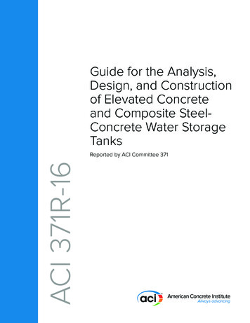
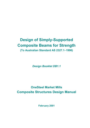
Composite Steel–Concrete Structures51-3FIGURE 51.2 Composite steel–concrete floors, Grosvenor Place, Sydney.FIGURE 51.3 Composite steel–concrete beams and slabs, car park, Australia.Other StructuresIn addition to bridges and buildings, composite slab and beam systems have seen considerable applicationin car park structures. Steel and steel–concrete composite construction provide a lighter structure withreduced foundation loads, as shown in Fig. 51.3.Case StudiesGrosvenor Place, SydneyGrosvenor Place is considered to be one of the more prestigious office buildings in Sydney, whichintegrates modern technology within the building fabric to allow office inhabitants great flexibility inthe manner in which it is occupied. The structural system of the building consists of an elliptical corewith radial steel beams, which span to a perimeter steel frame. These composite beams span up to 15 mand are designed to be composite for strength and serviceability. Furthermore, the beams also take accountof semirigidity by a specially designed connection to the elliptical core. 2003 by CRC Press LLC
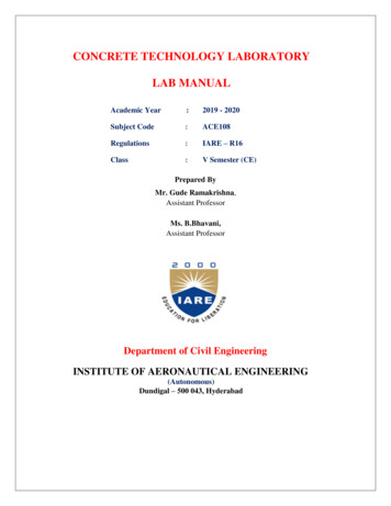
51-4The Civil Engineering Handbook, Second EditionFIGURE 51.4 Grosvenor Place, Sydney.The slabs are designed as one-way slabs, which consist of profiled steel sheeting spanning compositelybetween steel beams. The steel perimeter columns were designed as steel columns, although they areencased in concrete for fire resistance purposes, and are not designed compositely. The building is shownduring construction in Fig. 51.4.Forrest Place, PerthForrest Place is a multistory steel building that was designedwith a rectangular concrete core to resist lateral loads and iscombined with a perimeter steel frame, which consists of concrete-filled steel box columns. The beams were designed assteel–concrete composite beams, and the slabs are composite,utilizing permanent metal deck formwork. Elements of thebuilding during construction are shown in Fig. 51.5.Republic Plaza, SingaporeRepublic Plaza is one of the tallest buildings in Singapore andthus required an efficient structural system for both gravity andlateral loading. The building consists of an internal reinforcedconcrete shear core, and beams span to an external perimeterframe, which is actually coupled to the core for the purposes oflateral load resistance. The perimeter frame consists of concretefilled steel tubes that are designed compositely, as illustrated inFig. 51.6.One Raffles Link, SingaporeFIGURE 51.5 Composite construction,Forrest Plaza, Perth.This is an eight-story building with wide-span column-free spacespecially tailored for banking and financial sector clients. The composite floor slab is supported byprefabricated cellform beams, which act as main girders, and standard sections as secondary floor beams.The 18-m span girders comprise 1300-mm-deep cellform sections with regularly spaced 900-mm-diametercircular web openings, spaced at 1350-mm centers. The beams are fabricated from 914-deep, 305-widestandard I sections, cut and welded to achieve the desired depth. The cellform beam, as shown in Fig. 51.7,was preferred because it is lightweight and permits the passing of all building services through the beamweb. It therefore dispenses with the usual requirement of providing a dedicated services zone beneath thebeams. The service cores of the building have been utilized for resisting lateral loads. This design approachallowed the entire structural steel frame to be designed and detailed as pin connected. 2003 by CRC Press LLC
Composite Steel–Concrete Structures51-5FIGURE 51.6 Composite construction, Republic Plaza, Singapore.FIGURE 51.7 (a) One Raffles Link, Singapore. (b) Cellform beam.51.2 Composite Construction Systems for BuildingsComposite Floor SystemsComposite floor systems typically involve structural steel beams, joists, girders, or trusses made compositevia shear connectors, with a concrete floor slab to form an effective T-beam flexural member resistingprimarily gravity loads [2]. The versatility of the system results from the inherent strength of the concretefloor component in compression and the tensile strength of the steel member. The main advantages ofcombining the use of steel and concrete materials for building construction are: Steel and concrete may be arranged to produce an ideal combination of strength, with concreteefficient in compression and steel in tension. Composite systems are lighter in weight (about 20 to 40% lighter than concrete construction).Because of their light weight, site erection and installation are easier, and thus labor costs can beminimized. Foundation costs can also be reduced. 2003 by CRC Press LLC
51-6The Civil Engineering Handbook, Second EditionIn situ concreteIn situ concreteStud shearconnectorStud shearconnectorReinforcementSteel-sectionConcrete planksReinforcementSteel-sectionPrecast reinforced concrete planks with in situ concretetopping slabComposite beam with in situ concrete slab(a)(b)Prefabricatedconcrete slabIn situ concreteReinforcementstrapsStud shearconnectorIn situ concreteStud shearconnectorSteel sectionMetal deckingReinforcementSteel-sectionComposite beam floor using prefabricated concrete elementsComposite beam with in situ concrete slab ontrapezoidal metal decking(c)(d)FIGURE 51.8 Composite beams. The construction time is reduced, since casting of additional floors may proceed without havingto wait for the previously cast floors to gain strength. The steel decking system provides positivemoment reinforcement for the composite floor, requires only small amounts of reinforcement tocontrol cracking, and provides fire resistance. The construction of composite floors does not require highly skilled labor. The steel decking actsas permanent formwork. Composite beams and slabs can accommodate raceways for electrification, communication, and air distribution systems. The slab serves as a ceiling surface to provideeasy attachment of a suspended ceiling. The composite slab, when fixed in place, can act as an effective in-plane diaphragm, which mayprovide effective lateral bracing to beams. Concrete provides corrosion and thermal protection to steel at elevated temperatures. Compositeslabs of a 2-h fire rating can be easily achieved for most building requirements.The floor slab may be constructed by the following methods: a flat-soffit reinforced concrete slab (Fig. 51.8(a))precast concrete planks with cast in situ concrete topping (Fig. 51.8(b))precast concrete slab with in situ grouting at the joints (Fig, 51.8(c))a metal steel deck with concrete, either composite or noncomposite (Fig. 51.8(d))The composite action of the metal deck results from side embossments incorporated into the steelsheet profile. The composite floor system produces a rigid horizontal diaphragm, providing stability tothe overall building system, while distributing wind and seismic shears to the lateral load-resistingsystems. 2003 by CRC Press LLC
51-7Composite Steel–Concrete StructuresSimply supportedcomposite beam(a) PNAENA WORKINGLOADSULTIMATELOAD(b)FIGURE 51.9 (a) Composite floor plan. (b) Stress distribution in a composite cross section.Composite Beams and GirdersSteel and concrete composite beams may be formed by shear connectors connecting the concrete floorto the top flange of the steel member. Concrete encasement will provide fire resistance to the steel member.Alternatively, direct sprayed-on cementitious and board-type fireproofing materials may be used economically to replace the concrete insulation on the steel members. The most common arrangement foundin composite floor systems is a rolled or built-up steel beam connected to a formed steel deck and concreteslab (Fig. 51.8(d)). The metal deck typically spans unsupported between steel members, while alsoproviding a working platform for concreting work.Figure 51.9(a) shows a typical building floor plan using composite steel beams. The stress distributionat working loads in a composite section is shown schematically in Fig. 51.9(b). The neutral axis is normallylocated very near to the top flange of the steel section. Therefore, the top flange is lightly stressed. Froma construction point of view, a relatively wide and thick top flange must be provided for proper installationof shear studs and metal decking. However, the increased fabrication costs must be evaluated, which tendto offset the savings from material efficiency.A number of composite girder forms allow passage of mechanical ducts and related services throughthe depth of the girder (Fig. 51.10). Successful composite beam design requires the consideration ofvarious serviceability issues, such as long-term (creep) deflections and floor vibrations. Of particularconcern is the occupant-induced floor vibrations. The relatively high flexural stiffness of most compositefloor framing systems results in relatively low vibration amplitudes, and therefore is effective in reducingperceptibility. Studies have shown that short- to medium-span (6- to 12-m) composite floor beamsperform quite well and have rarely been found to transmit annoying vibrations to the occupants.Particular care is required for long-span beams of more than 12 m. 2003 by CRC Press LLC
51-8The Civil Engineering Handbook, Second EditionOpenings forservicesStiffenerFIGURE 51.10 Web opening with horizontal reinforcement.Rotate top halves about these positionsCutting patternShear connectorsComposite slabAVariable sizedduck openingATServiceductingSection A-AFIGURE 51.11 Composite castellated beams.Long-Span Flooring SystemsLong spans impose a burden on the beam design in terms of a larger required flexural stiffness forserviceability design. Besides satisfying serviceability and ultimate strength limit states, the proposedsystem must also accommodate the incorporation of mechanical services within normal floor zones.Several practical options for long-span construction are available, and they are discussed in the followingsubsections.Beams with Web OpeningsStandard castellated beams can be fabricated from hot-rolled beams by cutting along a zigzag line throughthe web. The top and bottom half-beams are then displaced to form castellations (Fig. 51.11). Castellatedcomposite beams can be used effectively for lightly serviced buildings. Although composite action doesnot increase the strength significantly, it increases the stiffness, and hence reduces deflection and theproblem associated with vibration. Castellated beams have limited shear capacity and are best used aslong-span secondary beams where loads are low or where concentrated loads can be avoided. Their usemay be limited due to the increased fabrication cost and the fact that the standard castellated openingsare not big enough to accommodate the large mechanical ductwork common in modern high-risebuildings.Horizontal stiffeners may be required to strengthen the web opening, and they are welded above andbelow the opening. The height of the opening should not be more than 70% of the beam depth, and thelength should not be more than twice the beam depth. The best location for the opening is in the lowshear zone of the beams. This is because the webs do not contribute much to the moment resistance ofthe beam. 2003 by CRC Press LLC
51-9Composite Steel–Concrete StructuresServicesFIGURE 51.12 Tapered composite beam.ServicesFIGURE 51.13 Haunched composite beam.Fabricated Tapered BeamsThe economic advantage of fabricated beams is that they can be designed to provide the required momentand shear resistance along the beam span in accordance with the loading pattern along the beam. Severalforms of tapered beams are possible. A simply supported beam design with a maximum bending momentat the midspan would require that they all effectively taper to a minimum at both ends (Fig. 51.12),whereas a rigidly connected beam would have a minimum depth toward the midspan. To make the bestuse of this system, services should be placed toward the smaller depth of the beam cross sections. Thespaces created by the tapered web can be used for running services of modest size (Fig. 51.12).A hybrid girder can be formed with the top flange made of lower strength steel than the steel gradeused for the bottom flange. The web plate can be welded to the flanges by double-sided fillet welds. Webstiffeners may be required at the change of section when the taper slope exceeds approximately 6 .Stiffeners are also required to enhance the shear resistance of the web, especially when the web slendernessratio is too high. Tapered beams are found to be economical for spans up to 20 m.Haunched BeamsHaunched beams are designed by forming a rigid moment connection between the beams and columns.The haunch connections offer restraints to the beam and help reduce midspan moment and deflection.The beams are designed in a manner similar to that of continuous beams. Considerable economy canbe gained in sizing the beams using continuous design, which may lead to a reduction in beam depthup to 30% and deflection up to 50%.The haunch may be designed to develop the required moment, which is larger than the plastic momentresistance of the beam. In this case, the critical section is shifted to the tip of the haunch. The depth ofthe haunch is selected based on the required moment at the beam-to-column connections. The lengthof haunch is typically 5 to 7% of the span length for nonsway frames or 7 to 15% for sway frames. Serviceducts can pass below the beams (Fig. 51.13).Haunched composite beams are usually used in the case where the beams frame directly into the majoraxis of the columns. This means that the columns must be designed to resist the moment transferredfrom the beam to the column. Thus a heavier column and more complex connection would be requiredthan would be with a structure designed based on the assumption that the connections are pinned. The 2003 by CRC Press LLC
51-10The Civil Engineering Handbook, Second EditionService ductsNon-composite dual beamService ductsComposite secondary beamsFIGURE 51.14 Parallel composite beam system.rigid frame action derived from the haunched connections can resist lateral loads due to wind withoutthe need for vertical bracing. Haunched beams offer higher strength and stiffness during the steel erectionstage, thus making this type of system particularly attractive for long-span construction. However,haunched connections behave differently under positive and negative moments, as the connection configuration is asymmetrical about the axis of bending.Parallel Beam SystemThis system consists of two main beams, with secondary beams running over the top of the main beams(see Fig. 51.14). The main beams are connected to either side of the column. They can be made continuousover two or more spans supported on stubs and attached to the columns. This will help in reducing theconstruction depth and thus avoid the usual beam-to-column connections. The secondary beams aredesigned to act compositely with the slab and may also be made to span continuously over the mainbeams. The need to cut the secondary beams at every junction is thus avoided. The parallel beam systemis ideally suited for accommodating large service ducts in orthogonal directions (Fig. 51.14). Small savingsin steel weight are expected from the continuous construction because the primary beams are noncomposite. However, the main beam can be made composite with the slab by welding beam stubs to the topflange of the main beam and connecting them to the concrete slab through the use of shear studs (seeStub Girder System below). The simplicity of connections and ease of fabrication make this long-spanbeam option particularly attractive.Composite TrussesComposite truss systems can be used to accommodate large services. Although the cost of fabrication ishigher in material cost, truss construction can be cost-effective for very long spans when compared withother structural schemes. One disadvantage of the truss configuration is that fire protection is laborintensive, and sprayed protection systems cause a substantial mess to the services that pass through theweb opening (see Fig. 51.15).Fire protectionFIGURE 51.15 Composite truss. 2003 by CRC Press LLC
51-11Composite Steel–Concrete StructuresShear connectorShear connectorT TTT T T TTStub welded tobottom chordTService zoneT TCompositesecondary beamFIGURE 51.16 Stub girder system.The resistance of a composite truss is governed by: (1) yielding of the bottom chord, (2) crushing of theconcrete slab, (3) failure of the shear connectors, (4) buckling of the top chord during construction,(5) buckling of web members, and (6) instability occurring during and after construction. To avoid brittlefailures, ductile yielding of the bottom chord is the preferred failure mechanism. Thus the bottom chordshould be designed to yield prior to crushing of the concrete slab. The shear connectors should have sufficientcapacity to transfer the horizontal shear between the top chord and the slab. During construction, adequateplan bracing should be provided to prevent top chord buckling. When considering composite action, thetop steel chord is assumed not to participate in the moment resistance of the truss, since it is located verynear to the neutral axis of the composite truss and thus contributes very little to the flexural capacity.Stub Girder SystemThe stub girder system involves the use of short beam stubs, which are welded to the top flange of acontinuous, heavier bottom girder member and connected to the concrete slab through the use of shearstuds. Continuous transverse secondary beams and ducts can pass through the openings formed by thebeam stub. The natural openings in the stub girder system allow the integration of structural and servicezones in two directions (Fig. 51.16), permitting story height reduction, compared with some otherstructural framing systems.Ideally, stub girders span about 12 to 15 m, in contrast to the conventional floor beams, which spanabout 6 to 9 m. The system is therefore very versatile, particularly with respect to secondary framingspans, with beam depths being adjusted to the required structural configuration and mechanical requirements. Overall girder depths vary only slightly, by varying the beam and stub depths. The major disadvantage of the stub girder system is that it requires temporary props at the construction stage, and theseprops have to remain until the concrete has gained adequate strength for composite action. However, itis possible to introduce an additional steel top chord, such as a T section, which acts in compression todevelop the required bending strength during construction. For span lengths greater than 15 m, stubgirders become impractical, because the slab design becomes critical.In the stub girder system, the floor beams are continuous over the main girders and splices at thelocations near the points of inflection. The sagging moment regions of the floor beams are usuallydesigned compositely with the deck slab system, to produce savings in structural steel as well as providestiffness. The floor beams are bolted to the top flange of the steel bottom chord of the stub girder, andtwo shear studs are usually specified on each floor beam, over the beam–girder connection, for anchorageto the deck slab system. The stub girder may be analyzed as a Vierendeel girder, with the deck slab actingas a compression top chord, the full-length steel girder as a tensile bottom chord, and the steel stubs asvertical web members or shear panels.Prestressed Composite BeamsPrestressing of steel girders is carried out such that the concrete slab remains uncracked under workingloads and the steel is utilized fully in terms of stress in the tension zone of the girder.Prestressing of steel beams can be carried out using a precambering technique, as depicted in Fig. 51.17.First, a steel girder member is prebent (Fig. 51.17(a)); then it is subjected to preloading in the directionagainst the bending curvature until the required steel strength is reached (Fig. 51.17(b)). Second, the 2003 by CRC Press LLC
51-12The Civil Engineering Handbook, Second Editiona)b)c)d)e)FIGURE 51.17 Process of prestressing using precambering technique.AnchorTendonsSteel sectionFIGURE 51.18 Prestressing of composite steel girders with tendons.lower flange of the steel member, which is under tension, is encased in a reinforced concrete chord(Fig. 51.17(c)). The composite action between the steel beam and the concrete slab is developed byproviding adequate shear connectors at the interface. When the concrete gains adequate strength, thesteel girder is prestressed by stress-relieving the precompressed tension chord (Fig. 51.17(d)). Furthercomposite action can be achieved by supplementing the girder with in situ or prefabricated reinforcedconcrete slabs; this will produce a double composite girder (Fig. 51.17(e)).The main advantage of this system is that the steel girders are encased in concrete on all sides: nocorrosion or fire protection is required for the sections. The entire process of precambering and prestressing can be performed and automated in a factory. During construction, the lower concrete chordcast in the works can act as formwork. If the distance between two girders is large, precast planks can besupported by the lower concrete chord, which is used as a permanent formwork.Prestressing can also be achieved by using tendons that can be attached to the bottom chord of a steelcomposite truss or the lower flange of a composite girder to enhance the load-carrying capacity andstiffness of long-span structures (Fig. 51.18). This technique is popular for bridge construction in Europeand the U.S., but it is less common for building construction.Composite Column SystemsComposite columns have been used for over 100 years, with steel-encased sections similar to that shownin Fig. 51.19(a) being incorporated in multistory buildings in the United States during the late nineteenth 2003 by CRC Press LLC
51-13Composite Steel–Concrete StructuresSteel sectionConcrete(a) Encased strut(b) Erection columnFIGURE 51.19 Encased composite sections.century [1]. The initial application of composite columns was for fire rating requirements of the steelsection [3]. Later developments saw the composite action fully utilized for strength and stability [4,5].Composite action in columns utilizes the favorable tensile and compressive characteristics of the steeland concrete, respectively. These types of columns are still in use today where steel sections are used aserection columns, with reinforced concrete cast around them as shown in Fig. 51.19(b). One majorbenefit of this system has been the ability to achieve higher steel percentages than conventional reinforcedconcrete structures, and the steel erection column allows rapid construction of steel floor systems insteel-framed buildings.Concrete-filled steel columns, as illustrated in Fig. 51.20, wereSteel sectiondeveloped much later during the last century but are still based onthe fundamental principle that steel and concrete are most effectivein tension and compression, respectively. The major benefits alsoinclude constructability issues, whereby the steel section acts aspermanent and integral formwork for the concrete. These columnswere initially researched during the 1960s, with the use of hot-rolledConcretesteel sections filled with concrete considered in Neogi et al. [6] andKnowles and Park [7,8]. These sections, while studied extensively,FIGURE 51.20 Concrete-filled steelwere essentially expensive, as the steel section itself was designed tocolumns.be hollow, thus requiring large steel plate thicknesses. This lack ofconstructional economy has seen the use of concrete-filled steelcolumns limited in their application throughout the world. Furthermore, restrictive cross section sizeshave rendered them unsuitable for application in tall buildings, where demand on axial strength is high.Japan has been an exception to the rule in regard to the application of concrete-filled steel columns.Widespread use of thick steel tubes or boxes has been invoked to provide confinement for the concreteand thus achieve greater ductility, which is desirable for cyclic loading experienced during an earthquake.The use of concrete-filled steel columns was initially justified after the Great Kanto Earthquake in 1923,when it was found that existing composite structures were relatively undamaged. This has resulted inmore than 50% of the building structures of over five stories in Japan being framed with compositesteel–concrete columns, as described by Wakabayashi [9].Recently in Australia, Singapore, and other developed nations, concrete-filled steel columns haveexperienced a renaissance in their use. The major reasons for this renewed interest are the savings inconstruction time, which can be achieved with this method. The major benefits include: The steel column acts as permanent and integral formwork. The steel column provides external reinforcement. The steel column supports several levels of construction prior to concrete being pumped.A
Composite Steel– Concrete Structures . connection to steel universal beams a softeel-framed structure. . Furthermore, design methods are herein summarized for various pertinent failure modes. Applications Composite construction has been mainly a