Transcription
Robust Stencil ShadowVolumesCEDEC 2001Tokyo, Japan
2Mark J. KilgardGraphics Software EngineerNVIDIA Corporation
3Games Begin to EmbraceRobust Shadows John Carmack’s new Doom engine leads the way First-class lights Vital to the look of the engine Cinematic shadowing effects Scary scenes possible
4Variety ofShadow dapproachesLight maps
5Stenciled Shadow VolumesTechnique that Carmack isusing for new Doom engineAdvantages Support omnidirectional lights Exact shadow boundariesDisadvantages Fill-rate intensive Expensive to compute shadow volumes Hard shadow boundaries, not soft shadows Difficult to implement robustlyShadowvolumes
6Let Us ConsiderOmni-directional Shadowing Situation: a light source centered in a room Dynamic characters in the room Everything should shadow everything This is a situation for stenciled shadow volumesLightsourceLightsource
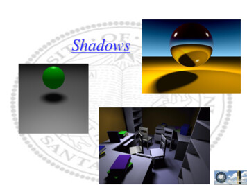
7Review:Stenciled Shadow Volumes A single point light source splits the world in two Shadowed regions Unshadowed regions Volumetric shadow technique A shadow volume is the boundary between theseshadowed and unshadowed regions Determine if an object is inside the boundary of theshadowed region and know the object is shadowed First described by [Crow 77]By the way, Frank Crowworks at NVIDIA now
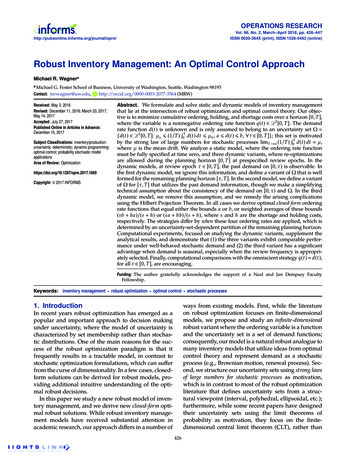
8Visualizing ShadowVolumes Occluders and light source cast out a shadowvolume Objects within the volume should be shadowedLightsourceScene with shadows froman NVIDIA logo casting ashadow volumeVisualization of theshadow volume
9Shadow VolumeAlgorithm High-level view of the algorithm Given the scene and a light source position,determine the shadow volume (harder than itsounds) Render the scene in two passes Draw scene with the light enabled,updating only fragments in unshadowed region Draw scene with the light disabled,updated only fragments in shadowed region But how to control update of regions?
102D Cutaway of aShadow VolumeShadowingobjectLightsourceEye position(note thatPartiallyshadows areshadowedindependent ofobjectthe eye position)Surface outsideshadow volume(illuminated)Shadowvolume(infinite extent)Surface insideshadow volume(shadowed)
11Tagging Pixels asShadowed or Unshadowed High-level algorithm does not say how toupdate only either pixels in or out of theshadow volume! The stenciling approach Clear stencil buffer to zero and depth buffer to 1.0 Render scene to leave depth buffer with closest Zs Render shadow volume into frame buffer withdepth testing but without updating color anddepth, but inverting a stencil bit This leaves stencil bit set within shadow!
12Stencil Inverting ofShadow Volume Why inverting stencil worksShadowingobjectLightsourceTwo inverts, left zeroOne invert, left oneEyepositionZero inverts, left zero
13Visualizing StenciledShadow Volume TaggingShadowed sceneStencil buffer contentsred stencil value of 1green stencil value of 0GLUT shadowvol example credit: Tom McReynolds
14ComputingShadow Volumes Harder than you might think Easy for a single triangle, just project out threeinfinite polygons from the triangle, opposite thelight position But shadow volume polygons should not intersecteach other for invert trick to work This makes things hard For complex objects, projecting object’s 2Dsilhouette is a good approximation (flat objects areeasy) Static shadow volumes can be pre-compiled
15Computing Shadow VolumesFor Polygonal Models High-level: determine “possible silhouette”edges of the model Transform light into object space Compute the plane equation for every polygon inthe model (can be pre-computed for static models) For every polygon in the model, determine if theobject-space light position is behind or in front ofthe polygon’s plane I.e., Is the planar distance from the polygon’s planeto the light positive or negative? Search for edges where polygons have oppositefacingness toward the light These edges are possible silhouette edges
16Examples of PossibleSilhouette Edges for ModelsAn object viewed from thesame basic direction that thelight is shining on the objecthas an identifiable light-viewsilhouetteAn object’s light-viewsilhouette appears quitejumbled when viewed form apoint-of-view that does notcorrespond well with thelight’s point-of-view
17For Shadow VolumesWith Intersecting Polygons Use a stencil enter/leave counting approach Draw shadow volume twice using face culling 1st pass: render front faces and increment whendepth test passes 2nd pass: render back faces and decrement whendepth test passes This two-pass way is more expensive than invert And burns more fill rate drawing shadow volumes Inverting is better if all shadow volumes have nopolygon intersections (very rare)
18Why Increment/DecrementStencil Volumes Work Example in 2DLightsourceShadowing objectzero 1zero 2Eyeposition 1 2 3
19Problems withNear Plane ClippingMissed shadowvolume intersectiondue to near clipplane clippingFar clipplanezero 1 1 2zero 3 2Near clipplane
20Capping Shadow Volumes atThe Near Clip PlaneMissed shadow volume intersection nowoccurs on the near clip plane becauseshadow volume edge is capped; keepsshadow volume enter/leave countscorrectzero 13D version ofthe problem isharder than 2Dcase! 1 2zero 3 2
21Shadow Volume Near PlaneClipping Artifacts Typically, shadow artifacts when light is behindobjectsLight source behind demon’s headCorrect shadows:Near plane capped properlyIncorrect shadows:Near plane NOT cappedIncorrect shadows: Projection ofsilhouette edges to the near clipplane shows capping isresponsible for the artifacts
22Alternative to Near PlaneCapping: Carmack’s Reverse Conventional shadow volume stencil usage Increment stencil when depth test passes for frontfacing shadow volume polygons Decrement stencil when depth test passes for backfacing shadow volume polygons John Carmack [1998?] reverses this usage Increment stencil when depth test fails for backfacing shadow volumes Decrement stencil when depth test fails for frontfacing shadow volume polygons
23Implications ofCarmack’s Reverse No longer have to worry about near clip planecapping But the reverse shifts the problem to that the farclip plane clipping shadow volumes Approach assumes that shadow volumes aretruncated and capped after a certain finite distancethat can never extend beyond the far clip plane Typically ok for attenuated lights Works ok because it is easier to move the far clipplane further out than move the near clip planecloser in
24More Implications ofCarmack’s Reverse Requires always truncating the shadow volumesand capping them some distance out Setting the far clip plane far in the distance toavoid shadow volume intersections doescompromise the available depth buffer precision A light very close to a shadowing polygon cancast a shadow so large that it fails to extend farenough
25Polygons Very Close to theLight Source Cause ProblemsCapped shadowvolumes work okwhen the light is areasonable distancefrom an occluderCapped shadowvolumes eventuallycollapse into anincreasinglymarginal volumewhen the light getsextremely close
26Carmack’s Doom Solution Uses Carmack’s reverse Support only attenuated lights Attenuation means illumination can be bounded Dynamically move far clip plane out to enclose light’smaximum region of illumination Clip shadow volumes to eliminate “light too close toshadowing polygon” case Extra clipping work Optimize spotlights Exploits light’s frustum
27A New Robust Technique forShadow Volume Capping Use stenciled shadow volume conventionally Rather than using Carmack’s Reverse Exploit rasterization with w 0 to draw semiinfinite polygons Details follow Adjust depth range and projection matrix toensure crack free near clip plane capping Details follow Result: Robust stenciled shadow volumealgorithm
28Rasterize This Polygon(1,3,z0,1)(-1,-3,z1,1)(2,-2,z2,1)
29Rasterize This Polygon(1,3,z0,1)(-1,-3,z1,1)(2,-2,z2,1)
30Rasterize This Polygon,One Vertex has W 0(1,3,z0,1)(-1,-3,z1,1)(2,-2,z2,0)
31Rasterize This Polygon,One Vertex has W 0(1,3,z0,1)(-1,-3,z1,1)(2,-2,z2,0)
32Rasterize This Polygon(1,3,z0,1)(-1,-3,z1, 0)(2,-2,z2,0)
33Rasterize This Polygon,Two Vertices have W 0(1,3,z0,1)(-1,-3,z1,0)(2,-2,z2,0)
34OpenGL Renders W 0Polygons Correctly OpenGL implementations are required to rendertriangles properly when vertices have w 0 Because of how the “possible silhouettes” forshadow volumes project on the near clip plane,rendering triangles with w 0 provides correctcapping Because we really need to be rendering semiinfinite polygons That’s what w 0 vertices are all about
35Near Clip PlaneCapping Cases A “possible silhouette” is a loop of vertices on anoccluding model Given a light position, this loop can be projectedonto the near clip plane We are only interested in projecting AWAY from thelight (shadows just project away from a light)Three possibilities1. No vertices on the loop project away to the near clipplane (trivial case, no capping required)2. All vertices on the loop project away to the near clipplane (easy capping case)3. Some but not all of the loop vertices project awayonto the near clip plane (hard capping case)
36Handling the “Trivial” NoneNear Clip Plane Capping Case None of the rays cast away from the light sourceintersect with the near clip plane Render a quad strip loop using “possiblesilhouette” vertices and infinite vertices (withw 0) where x, y, and z are the direction away fromthe light The w 0 vertices are easier to compute than tryingto extend the shadow volume some sufficientlylarge finite distance Avoid all worries that the large finite distance usedmay not actually be sufficient
37Handling the “Easy”Near Clip Plane Capping Case Intersect each ray cast away from the light sourcewith the near clip plane Render a quad strip loop using “possiblesilhouette” vertices and the near clip planeintersection positions Project all the model’s triangles that are withinthe “possible silhouette” loop (i.e., facing awayfrom the light) to the near clip plane and renderthem
38Handling the “Hard” NearClip Plane Capping Case (1) In this case, the “possible silhouette” loopprojects AWAY onto the near clip plane for someloop vertices, but not all Render a quad strip loop using “possiblesilhouette” vertices and a projected position If the ray cast from a loop vertex away from thelight intersects the near clip plane, use theintersection position for the projected position Send two vertices for the quad strip loop: the loopvertex and its projected position Otherwise, Send two vertices for the quad strip loop: the loopvertex and its direction away from the light forXYZ and with w 0
39Handling the “Hard” NearClip Plane Capping Case (2) For each triangle within the “possible silhouette”loop (i.e., facing away from the light) If all three vertices do not project AWAY to the nearclip plane, skip this triangle If all three vertices do project AWAY to the nearclip plane, render a triangle from these projectedvertices If one or two vertices project AWAY to the near clipplane, but not all three, these are handled asdescribed on the next two slides
40Handling the “Hard” NearClip Plane Capping Case (3) If exactly one vertex projects AWAY to the near clipplane, render a triangle with this projected vertexand two vertices with w 0 as described The two remaining vertices are determined bycomputing the plane containing the light position,the single projected vertex position on the near clipplane, and one of the two remaining loop vertices Then take the cross product of the direction of thisplane and the near clip plane Render a triangle with the single projected vertexposition and two other vertices such that the XYZ ofthese two vertices is the direction vector result fromthe cross product and w 0
41Handling the “Hard” NearClip Plane Capping Case (4) If exactly two vertices project AWAY to the nearclip plane, render a quad with these two projectedvertices and two other vertices with w 0 asdescribed Determine the third vertex by computing the planecontaining the light position, one of the twoprojected vertices, and the unprojected loop vertex Then take the cross product of the direction of thisplane and the near clip plane The third vertex is such that XYZ is the directionvector results from the cross product and w 0 Compute the fourth vertex in the same manner usingthe remaining projected vertex
42“Hard” Case Example Consider a point light source in a box open on oneside, facing the viewer (a.k.a. the lantern case)Intersects thenear clip plane 1zero
43“Hard” Case Example Lantern case requires w 0 cappingCapping requires 4 w 0quads rendered at thenear clip planeOutwardcappingrequired 1zero 1 1zero 1Side viewFront view 1
44Remaining Issues We must be extra careful to not introduce crackswhen capping a stencil shadow volume at thenear clip plane We expect to draw the model in object space sowould naturally render the shadow volume and capit in object space too The near clip plane capping must not introduceany T-junctions So far, we say that we are drawing the polygonsat the near clip plane to cap our shadow volumes However, the near clip plane is a razor’s edgewhere polygons exactly or nearly coincident withthe near clip plane may indeed be clipped
45Building a “Ledge” at theFront of the Depth Buffer We would like to configure the depth buffer andprojection matrix as follows:0.05 ledgehalfwayn' 0.0 n 0.1Shadow volume depth rangeScene depth rangef 1.0 The scene would be drawn in the range [0.1 . 1.0] The shadow volumes would be drawn in therange [ 0.0 . 1.0 ] Shadow volume capping would be drawn at 0.05,the ledge halfway plane Depth values from the scene and shadowvolumes must be comparable
46Shared Vertices for ShadowVolume Capping on LedgeBoundary for shadow volume view frustumBoundary for scene view frustumzero 1Must sharevertices toavoid cracks!0.05 ledgehalfwayn' 0.0 n 0.1 1 2zeroShadow volume depth rangeScene depth rangef 1.0
47Math for Building a “Ledge”At Front of Depth Buffer (1) Setting depth range and projection matrixNote: The Z row andonly the Z rowdepends on F and NglDepthRange(f, n);gluPerspective(fov, aspect, N, F);X and Y positions can& will be bit exact ifonly Z row changes gluPerspective builds 4x4 matrixfov/aspect0000fov0000(F N)/(N-F)(2*F*N)/(N-F)00-10
48Math for Building a “Ledge”At Front of Depth Buffer (2) Given n, f, N, and F, and a closer depth range near value n',can we determine a value N' for the gluPerspective call thatwill make the depth values using n, f, N, and F comparableto the depth values generated using n', f, N', and F ? Being comparable mathematically means:(FN)/(N-F) z (2*F*N)/(N-F)(f-n) *2(n f)2-z (FN')/(N'-F) z (2*F*N')/(N'-F)(f-n') *2-z(n' f)2
49Math for Building a “Ledge”At Front of Depth Buffer (3) The expression(FN)/(N-F) z (2*F*N)/(N-F)(f-n) *2(n f)2-z (FN')/(N'-F) z (2*F*N')/(N'-F)(f-n') *(n' f)22-zdoes simplify so that z cancels out of the expression. Thismeans z is comparable. Moreover, N' can be expressed interms of n, f, N, F, and n':N' - (f - n) * F * Nn * N - f * F - n' * (F - N)
50Issue: How to ProperlyTessellate Capping Polygons Rendering polygons at near clip plane properlycaps shadow volumes But proper capping is hard if you only assume thatyou know the outlineTrivial to cap the outlineof a single triangleNon-trivial if just given a complexshadow volume intersection withthe near clip plane
51Solution: Project ObjectPolygons to Near Plane Tessellating from an outline is a hard problem Involved computational geometry problem But we have more information than the outline Capping tessellation on the near clip plane is reallyjust a projection of object’s back facing geometry(with respect to the light) onto the near clip plane So render the capping geometry on the nearclip plane by projection object’s back facinggeometry to the near clip plane
52Incrementing for ProjectedPolygons Causes Errors Naively, increment stencil for projected cappingpolygons Consider the following two situations 1 1 1 2 1 1 1Good Case:Incrementing workscorrectly, all pixels insideoutline are incrementedBad Case: But when interiorvertex is outside of outline,incorrect double incrementingoccurs outside the outline!
53When Does theBad Case Occur Numerical error in transformation can lead tointerior vertices that are barely outside of theoutline when projected to screen space Trust me – it happens If not corrected, double incrementing of regionsthat should not be incremented at all leads tospurious shadowed pixels Only a few pixels, but obvious Particularly obvious when animating
54Example of Bad CaseNotice how the bogus Bogus Shadowed polygonal region shadowed polygon isdue to naïve cappingnear the capping outline
55Examine the Bad Case inMore Detail Examine polygon facing-ness for the two ingback-facingfront-facingfront-facingGood CaseBad Case
56Solution: Increment FrontFaces, Decrement Back Faces Draw capping polygons twice Increment stencil for front faces Decrement stencil for back faces 1 -1 0 1 1 1 1All faces front facing 1 1Region that was doubleincremented is now left zerobecause it is bothincremented & decremented
57Performance Implications Is drawing capping polygons twice expensive? Not really Most capping polygons are front-facing Rarely are back-facing polygons encountered When back-facing polygons occur, there is anextra overhead of incrementing and decrementingpixels (pixel touched twice for no net effect) Modern hardware culls wrong-facing polygons atamazing rates Hardware setup can cull 25 million wrong-facingpolygons per second Moreover, the alternative is bogus shadowing
58High-level Shadow VolumePerformance Optimization Key performance problem with shadow volumes shadow volumes consume invisible fill rate If you plan to use shadow volumes Invest early on in developing a robust algorithm Analyze your maps to eliminate shadow volumesthat cannot be seen Example: shadows completely behind walls Do not overextend shadow volumes Example: do not extend shadow volumes past walls Carmack’s optimizations in these areas willmake new Doom engine awesome
59Combining Shadow VolumesWith Bump Mapped Modelsmd2shader demo/example
7 Review: Stenciled Shadow Volumes A single point light source splits the world in two Shadowed regions Unshadowed regions Volumetric shadow technique A shadow volume is the boundary between these shadowed and unshadowed regions Determine if an object is inside the boundary of the shadowed r