Transcription
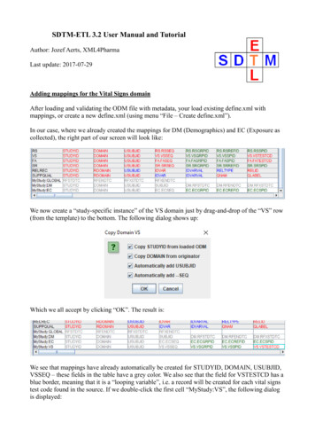
Texture and other MappingsShadowsShadowsTextureTexture MappingMappingBumpBump MappingMappingDisplacementDisplacement MappingMappingEnvironmentEnvironment MappingMappingAngel Chapter 7COMPUTER GRAPHICS15-462Computer Graphics 15-4621
Announcements Written assignment #1 back later next week.Computer Graphics 15-4622
ShadowsShadows occur where objects are hidden from a light source Omit any intensity contribution from hidden light sources Umbra and penumbra (function of size of light source) Soft shadows and hard shadows (point light source at a distance) Important perceptual clue for connecting objects to ground (feet inparticular) But object-to-object shadows also important In general, shadows from many light sourcesComputer Graphics 15-4623
Planar Projection ShadowsSimplest case:Point light source (no penumbra) and shadows only onthe ground planeGood for flight simulatorsShadow is projection of polygononto the surface with the centerof projection at the light sourceComputer Graphics 15-4624
Planar Projection ShadowsPut light source at origin with T ( x1 , y1 , z1 )Simple perspectiveprojection through theorigin:M 100 0010 0001 00 1 / y1 0 0Translate back withT ( x1 , y1 , z1 )Computer Graphics 15-4625
Planar Projection Shadows in OpenGLGlFloat m[16]; /* shadow projection matrix */For (i 0;i 15;i ) m[i] 0.0;m[0] m[5] m[10] 1.0; m[7] -1.0/y1;glBegin(GL POLYGON);/* draw the polygon normally */glEnd();glMatrixMode(GL MODELVIEW);glPushMatrix(); /* save state*/glTranslatef(x1,y1,z1); /* translate back */glMultMatrixf(m); /* project*/glTranslate(-x1,-y1,-z1); /* move light toorigin */glColor3fv(shadow color);glBegin(GL POLYGON);/* draw the polygon again */glEnd();glPopMatrix(); /* restore state */Computer Graphics 15-4626
Question If a perspective transform does a point lightsource, what does a directional light source? [Angel demo]Computer Graphics 15-4627
Limitations of Planar Projection Shadows Only do shadows on flat surfaces Objects must be far enough apart to not castshadows on each other—although artifacts oftenhard to detect. Related approach:projective textures(Blurred drop shadow texturefrom video game “Halo”)Computer Graphics 15-4628
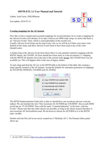
Other Shadow AlgorithmsShadow Maps (Williams, 1978): Z-Buffer algorithmWorks for curved surfaces1. Render from light source to compute depth map (z distance toclosest object for each pixel in the map).2. While rendering, if a point (x,y,z) is visible, map (x,y,z) in the coordinatesof the viewpoint to (x’,y’,z’), the coordinates of the point from the light.3. If z’ is greater than the value in the z-buffer for that point, then a surface isnearer to the light source than the point under consideration and the pointis in shadow. If so, render with a shadow intensity, if not render asnormal. Handles multiple light sources (with multiple z-buffers),moving objects and lights (at the cost of several renderings).Clearly a winning strategy with hardware.Computer Graphics 15-4629
Shadow Maps (Williams, 1978)Computer Graphics 15-46210
Other Shadow AlgorithmsProjecting polygons—scan line (Appel 1968)Build a data structure that links all polygons where one might shadow theother (depends on polygon location and lighting source location—animationwould require recalculating). Multiple data structures for multiple lights.When scan converting have three possibilities Shadow polygon does not cover generated scan line segment Shadow polygon completely covers segment (adjust intensity for shadow) Shadow polygon partially covers segment, subdivide and repeatPoint light sourcePolygon APolygon BScanlineView pointComputer Graphics 15-462Shadow of A on B11
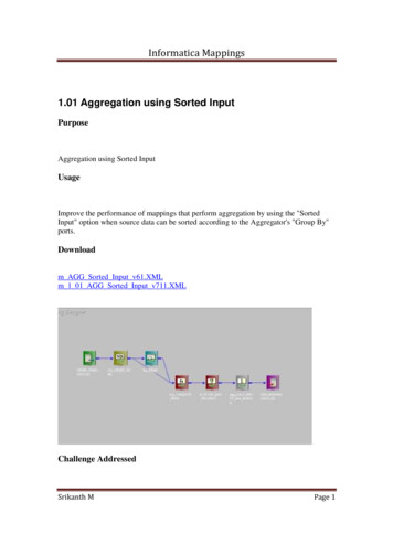
Other Shadow AlgorithmsShadow Volumes (Crow 1977)Compute the volume of space swept out by an object, intersected withthe viewing volume.Include these invisible objects in rendering pipeline.Render visible objects as in shadow if they are in front of a back facingshadow polygon and in back of a front facing polygon. Extend the zbuffer to contain this extra information.Point light sourcePolygonIntersection of shadowvolume with view volumeView volumeComputer Graphics 15-46212
Examples: Shadow VolumesComputer Graphics 15-46213
Texture MappingComputer Graphics 15-46214
Last time we talked about shading. But uniformlycolored or shaded surfaces are unrealistic. Real objects have small surface features One option: use a huge number of polygons withappropriate surface coloring and reflectancecharacteristics Another option: use a mapping algorithm to modify theshading algorithm– Texture mapping– Bump mapping– Displacement mapping– Environmental mappingComputer Graphics 15-46215
The Quest for Visual RealismComputer Graphics 15-46216
2D Texture MappingTexture images to make our surfaces more life-likeScan textures from the world (clouds, wood grain) or paint them yourselfStore the texture in a 2D imageMap the image onto the surface by a function which maps (u,v)coordinates of our parametric surface onto (x,y) image coordinatesWhen shading a surface point, we look up the appropriate pixel from the2D image, and use that to affect the final colorVoila! Your favorite picture painted onto a donut.This technique is calledparametric texture mappingBut how to map from texturecoordinates to object coordinates?Easy for a parametric surface,less obvious for other models.Computer Graphics 15-46217
Texture Mapping: GeneralTexture SpaceT (u )T (u , v )T (u , v, w)Computer Graphics 15-462Object Space( xw , y w , z w )18Screen Space( xs , y s )
Specifying the Mapping FunctionSome objects have natural parameterizations:– Sphere: use spherical coordinates (φ,θ) (2πu,πv)– Cylinder: use cylindrical coordinates (u,θ) (u,2πv)Computer Graphics 15-46219
Specifying the Mapping FunctionSome objects have natural parameterizations:– Parametric surface (such as B-spline or Bezier): use patchparameters (u,v)u umin v vmin s sminsmax smint t mint max t min(umax umin )(vmax vmin )Computer Graphics 15-462Doesn’t take intoaccount the curvatureof the surface: stretching.Just like with roller coaster.20
Specifying the Mapping FunctionWhat about arbitrary polygonal objects?Two step mapping: To a canonical shape first Then project normals from objecta) From texture value to objectb) Use normals to find texturec) Line from center to point totexture valueComputer Graphics 15-46221
Or design the mapping by handComputer Graphics 15-46222
Demo: “uvMapper” www.uvmapper.comComputer Graphics 15-46223
Texture Mapping in OpenGLA parallel pipeline for pixel operations:Texture mapping is part of the shadingprocessComputer Graphics 15-46224
Texture Mapping in OpenGLGlubyte my texels[512][512];glTexImage2D(GL TEXTURE 2D, 0, 3, 512, 512, 0,GL RGB,GL UNSIGNED BYTE, my texels);/* level, components, w, h, border, format, type, tarray */glEnable(GL TEXTURE 2D);/* assign texture coordinates */glBegin(GL QUAD);glTexCoord2f(0.0, 0.0);glVertex2f(x1,y1,z1);glTexCoord2f(1.0, f(x4,y4,z4);glEnd();Computer Graphics 15-46225
Grungy details we’ve ignored Specify s or t out of range? Use GL TEXTURE WRAP inglTexParameter because many textures are carefully designed torepeat Aliasing? Mapping doesn’t send you to the center of a texel. Canaverage nearest 2x2 texels using GL LINEAR Mipmapping: use textures of varying resolutions. 64x64 becomes32x32,16x16,8x8,4x4,2x2 and 1x1 arrays withgluBuild2DmipmapsComputer Graphics 15-46226
What is aliasing? Sampling error when mapping texture images to screenComputer Graphics 15-46227
What is aliasing? An on-screen pixel may not map neatly to a texel.Computer Graphics 15-46228
Example: Checkerboard Particularly severe problems in regular texturesComputer Graphics 15-46229
The Beginnings of a Solution: Mipmapping Pre-calculate how the texture should look at various distances, thenuse the appropriate texture at each distance. This is calledmipmapping. “Mip”“multum in parvo” or “many things in a small place” Each mipmap (each image below) represents a level of resolution. Powers of 2 make things much easier.Computer Graphics 15-46230
The Beginnings of a Solution Problem: Clear divisions between different depth levels Mipmapping alone is unsatisfactory.Computer Graphics 15-46231
Another Component: Filtering Take the average of multiple texels to obtain the finalRGB value Typically used along with mipmapping Bilinear filtering– Average the four surrounding texels– Cheap, and eliminates some aliasing, but does not help with visibleLOD divisions(demonstration movies)Computer Graphics 15-46232
Another Component: Filtering Trilinear filtering– Interpolate between two LODs– Final RGB value is between the result of a bilinear filter at oneLOD and a second bilinear filter at the next LOD– Eliminates “seams” between LODs– At least twice as expensive as bilinear filteringComputer Graphics 15-46233
Another Component: Filtering Anisotropic filtering– Basic filtering methods assume that a pixel on-screen maps toa square (isotropic) region of the texture– For surfaces tilted away from the viewer, this is not the case!Figure 5. Anisotropic footprints are very common.Image courtesy of nVidiaComputer Graphics 15-46234
Another Component: Filtering Anisotropic filtering– A pixel may map to a rectangular or trapezoidal section oftexels—shape filters accordingly and use either bilinear ortrilinear filtering– Complicated, but produces very nice resultsComputer Graphics 15-46235
Bilinear FilteringComputer Graphics 15-46236ID Software
Trilinear FilteringComputer Graphics 15-46237ID Software
Anisotropic FilteringComputer Graphics 15-46238ID Software
Side-by-Side ComparisonnVidiaComputer Graphics 15-46239
Texture GenerationPhotographsDrawingsProcedural methods (2D or 3D)Associate each x,y,z value directly withan s,t,r value in the texture block(sculpting in marble and granite)Computer Graphics 15-46240
Procedural MethodsReaction-DiffusionGreg Turk, Siggraph ‘91Computer Graphics 15-46241
Solid Textures Have a 3-D array of texture values (e.g., ablock of marble)– Use a function [xyz] - [RGB] to map colors topoints in space Such a 3D map is called a solid texture map In practice the map is often definedprocedurally– No need to store an entire 3D array of colors– Just define a function to generate a color foreach 3D point The most interesting solid textures arerandom ones– a great marble algorithm has now becomecliché Evaluate the texture coordinates in objectcoordinates - otherwise moving the objectchanges its texture!Computer Graphics 15-46242From: An Image Synthesizerby Ken Perlin, SIGGRAPH '85
Uses for Texture Mapping (Heckbert 1986)Use texture to affect a variety of parameters surface color(Catmull 1974) surface reflectance normal vector geometry transparency light source radianceComputer Graphics 15-462- color (radiance) of each point on surface- reflectance coefficients kd, ks, or nshiny- bump mapping (Blinn 1978)- displacement mapping- transparency mapping (clouds) (Gardener 1985)- environment mapping (Blinn 1978)43
Radiance vs. Reflectance Mapping Sphere w/ Uniform Diffuse coefficient Radiance MapSphere w/ Radiance MapTexture specifies (isotropic) radiance for each point on surface Sphere w/ Uniform Diffuse coefficient Reflectance (kd) MapSphere w/ Reflectance MapTexture specifies diffuse color (kd coefficients) for each point on surface- three coefficients, one each for R, G, and B radiance channelsComputer Graphics 15-46244
Multitexturing(See RedBook p.422 for details)Computer Graphics 15-46245
Bump Mapping: A Dirty Trick Which spots bulge out, and which are indented? Answer: None! This is a flat image. The human visual system is hard-coded to expect light from above In CG, we can perturb the normal vector without having to makeany actual change to the shape.Computer Graphics 15-46246
Bump Mapping Basic texture mapping paints on to a smooth surface How do you make a surface look rough?– Option 1: model the surface with many small polygons– Option 2: perturb the normal vectors before the shading calculationReal BumpFake Bump Sphere w/Diffuse Texture MapComputer Graphics 15-462Flat Plane Bump Map47Sphere w/Diffuse Texture Bump Map
Bump Mapping Basic texture mapping paints on to a smooth surface How do you make a surface look rough?– Option 1: model the surface with many small polygons– Option 2: perturb the normal vectors before the shading calculation» the surface doesn’t actually change, but shading makes it look that way» bump map fakes small displacements above or below the true surface» can use texture-mapping for this– texture image gives amount to perturb surface normalWhat kind of anomaly will this produce?Greg TurkComputer Graphics 15-46248
Bump MappingLet p(u, v ) be a point on a parametric surface.Unit normal is n p u p v pu p v Where x v ypv v z v x u ypu u z uare partial derivative vectors tangent to thesurface at point PComputer Graphics 15-46249
Bump MappingDisplace the surface in the normal directionby d (u , v )Thenp' p d (u , v )nWe don’t actually change the surface (p), justthe normal. Need to calculate:n' p p'uComputer Graphics 15-462'v50
Bump MappingCompute the partial derivatives bydifferentiating p’ d'p u pu n d (u , v)n u u d'p v pv n d (u , v)n v vIf d is small d dn' n vn pv d dPre-compute arrays of, v uComputer Graphics 15-46251 un pu
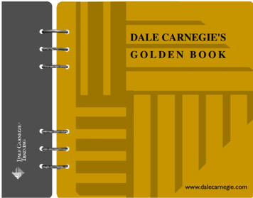
Bump Mapping We can perturb the normal vector without having tomake any actual change to the shape. This illusion can be seen through—how?Original model (5M)Computer Graphics 15-462Simplified (500)52Simple model with bump map
Another Bump Mapping Example Bump MapCylinder w/Diffuse Texture MapComputer Graphics 15-46253
Displacement Mapping Use texture map to displace each point on the surface– Texture value gives amount to move in direction normal to surface How is this different from bump mapping?Computer Graphics 15-46254
Environment MappingSpecular reflections that mirror the environmentComputer Graphics 15-46255
Environment MappingSpecular reflections that mirror the environmentCube is a naturalintermediate objectfor a roomComputer Graphics 15-46256
Environment Mapping Generate the environment map either by scanning or by renderingthe scene from the point of view of the object (win here becausepeople’s ability to do the reverse mapping in their heads is bad—they won’t notice flaws) OpenGL can automatically generate the coordinates for a sphericalmapping. Given a vertex and a normal, find point on sphere thathas same tangent:glTexGenfv(GL S, GL SPHERE MAP,0);glTexGenfv(GL T,GL SPHERE MAP,0);glEnable (GL TEXTURE GEN S);glEnable (GL TEXTURE GEN T);Computer Graphics 15-46257
Environment Mapping: Cube MapsComputer Graphics 15-46258
More Tricks: Light Mapping Quake uses light maps in addition to (radiance) texture maps. Texturemaps are used to add detail to surfaces, and light maps are used tostore pre-computed illumination. The two are multiplied together atrun-time, and cached for efficiency.Radiance Texture Map OnlyRadiance Texture Light MapLight MapComputer Graphics 15-46259
Other Shadow Algorithms Shadow Volumes (Crow 1977) Compute the volume of space swept out by an object, intersected with the viewing volume. Include these invisible objects in rendering pipeline. Render visible objects as in shadow if they are in front of a back facing shadow polygon and in back