Transcription
Cisco UCS B480 M5Blade ServerCISCO SYSTEMS170 WEST TASMAN DR.SAN JOSE, CA, 95134WWW.CISCO.COMPUBLICATION HISTORYREV D.13JUNE13, 2022
CONTENTSOVERVIEW . . . . . . . . . . . . . . . . . . . . . . . . . . . . . . . . . . . . . . . . . . . . . . .DETAILED VIEWS . . . . . . . . . . . . . . . . . . . . . . . . . . . . . . . . . . . . . . . . . . .BASE SERVER STANDARD CAPABILITIES and FEATURES . . . . . . . . . . . . . . . . .CONFIGURING the SERVER . . . . . . . . . . . . . . . . . . . . . . . . . . . . . . . . . . . .2346STEPSTEPSTEP1 CHOOSE SERVER SKU . . . . . . . . . . . . . . . . . . . . . . . . . . . . . . . . . . . . . . . . . . . 72 CHOOSE CPU(S) . . . . . . . . . . . . . . . . . . . . . . . . . . . . . . . . . . . . . . . . . . . . . . 83 CHOOSE MEMORY . . . . . . . . . . . . . . . . . . . . . . . . . . . . . . . . . . . . . . . . . . . . 12STEPSTEPSTEPSTEPSTEPSTEPSTEPSTEPSTEPSTEP4 CHOOSE OPTIONAL FRONT MEZZANINE: Storage Controller or GPU . . . . . . . . . . . . 225 CHOOSE HARD DISK DRIVES or SOLID-STATE DRIVES (OPTIONAL) . . . . . . . . . . . . . . 256 CHOOSE REAR MEZZANINE CARDS . . . . . . . . . . . . . . . . . . . . . . . . . . . . . . . . . . 307 ORDER A TRUSTED PLATFORM MODULE (OPTIONAL) . . . . . . . . . . . . . . . . . . . . . . 358 CHOOSE OPTIONAL SECURE DIGITAL CARDS or M.2 DEVICES . . . . . . . . . . . . . . . . 369 ORDER INTERNAL USB 3.0 DRIVE (OPTIONAL) . . . . . . . . . . . . . . . . . . . . . . . . . . 3910 CHOOSE OPERATING SYSTEM AND VALUE-ADDED SOFTWARE . . . . . . . . . . . . . . . 4011 CHOOSE OPERATING SYSTEM MEDIA KIT (OPTIONAL) . . . . . . . . . . . . . . . . . . . . 4412 CHOOSE SERVICE and SUPPORT LEVEL . . . . . . . . . . . . . . . . . . . . . . . . . . . . . . 4513 CHOOSE LOCAL KVM I/O CABLE (OPTIONAL) . . . . . . . . . . . . . . . . . . . . . . . . . . 52DIMM Memory Mirroring . . . . . . . . . . . . . . . . . . . . . . . . . . . . . . . . . . . . . 15System Speeds . . . . . . . . . . . . . . . . . . . . . . . . . . . . . . . . . . . . . . . . . . . 17SUPPLEMENTAL MATERIAL . . . . . . . . . . . . . . . . . . . . . . . . . . . . . . . . . . .NETWORK CONNECTIVITY . . . . . . . . . . . . . . . . . . . . . . . . . . . . . . . . . . . .SPARE PARTS . . . . . . . . . . . . . . . . . . . . . . . . . . . . . . . . . . . . . . . . . . . .UPGRADING or REPLACING CPUs . . . . . . . . . . . . . . . . . . . . . . . . . . . . . . .DISCONTINUED EOL PRODUCTS . . . . . . . . . . . . . . . . . . . . . . . . . . . . . . . .TECHNICAL SPECIFICATIONS . . . . . . . . . . . . . . . . . . . . . . . . . . . . . . . . . .1536061697280Cisco UCS B480 M5 Blade Server
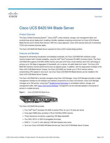
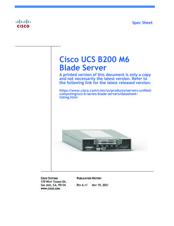
OVERVIEWOVERVIEWDesigned for demanding virtualization and database workloads, the UCS B480 M5 combines a large memoryfootprint with four-socket scalability, leveraging the 2nd Generation Intel Xeon Scalable Processors. TheUCS B480 M5 supports 2933-MHz GB DDR4 memory DIMMs, all in a dense, full-width blade form factor. TheUCS B480 M5 maintains memory performance even as capacity grows and can support up to 6 TB of memorywithout compromise to CPU speed or core count. Up to four UCS B480 M5 Blade Servers can be installed inthe UCS 5108 Blade Server Chassis.The Cisco B480 M5 includes support for the following: 2nd Generation Intel Xeon Scalable Processors. DDR4-2933MHz memory DIMMs. 128 GB, 256 GB, and 512 GB Intel Optane Persistent Memory (PMem). Up to 18 TB of memory is available if the memory slots are populated as follows:—24 x 256 GB DDR4 DIMMs—24 x 512 GB PMemThe UCS B480 M5 Blade Server is centrally managed using Cisco UCS Manager. Cisco UCSM provides a singlemanagement interface for all hardware and software components of a UCS domain. Cisco UCSM manages upto 160 servers, using Single Connect Technology to consolidate network, storage, and management traffic.With Cisco UCS Central, management can be extended globally to ‘of servers in multiple domains.Figure 1Cisco UCS B480 M5 Blade ServerCisco UCS B480 M5 Blade Server2
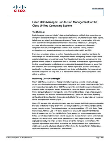
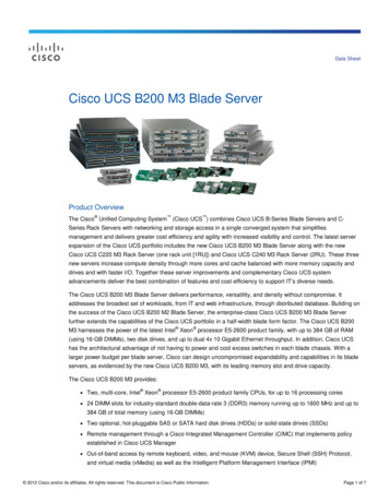
DETAILED VIEWSDETAILED VIEWSBlade Server Front ViewFigure 2 is a detailed front view of the Cisco UCS B480 M5 Blade Server.Figure 2Blade Server Front View1Drive bay 1 (populated)8Power button and LED2Drive bay 2 (populated)9Network link status and LED3Drive bay 310Blade health LED4Drive bay 411Local console connection15Left ejector handle12Reset button6Asset pull handle13Locate (identify) button and LED14Ejector thumb screw(a blank asset tag is provided on whichyou can add your own label or sticker oryou can use a marker to write your assetinformation on the tag)7Right ejector handleNotes1. For information about the KVM local I/O cable that plugs into the console connector (a cable is included withevery Cisco UCS 5108 blade server chassis accessory kit), see CHOOSE LOCAL KVM I/O CABLE (OPTIONAL) onpage 53.3Cisco UCS B480 M5 Blade Server
BASE SERVER STANDARD CAPABILITIES and FEATURESBASE SERVER STANDARD CAPABILITIES and FEATURESTable 1 lists the capabilities and features of the base server. Details about how to configure the server fora particular feature or capability (for example, number of processors, disk drives, or amount of memory)are provided in CONFIGURING the SERVER on page 6.NOTE: The B480 M5 blade server requires UCS Manager (UCSM) to operate as part ofthe UCS system. The B480 M5 with the Intel Xeon Scalable processor family of CPUs requiresUCSM 3.2(2) or later release, and with the 2nd Generation Intel ScalableProcessors, UCSM 4.0(4b) is required.Table 1 Capabilities and FeaturesCapability/FeatureDescriptionBlade server chassisThe full-width UCS B480 M5 Blade Server mounts in a Cisco UCS 5108 seriesblade server chassis.CPUTwo or four 2nd Generation Intel Xeon Scalable family CPUsChipsetIntel C621 series chipset (Lewisburg)Memory48 total DIMM slotsI/O Support for Advanced ECC Support for registered ECC DIMMs (RDIMMs) Support for load-reduced DIMMs (LRDIMMs) Support for Intel Optane Persistent Memory (PMem)Five configurable mezzanine slots: One rear mLOM slot supports the Cisco VIC 1440 only.NOTE: The Cisco VIC 1400 Series (1440 and 1480) is compatible with6200, 6300, 6400 and 6536 Series Fabric Interconnects as well as the2204XP, 2208XP, 2304V2, and 2408XP Fabric Extenders. Two rear mezzanine slots support Cisco adapters and Cisco UCS StorageAccelerator or GPUs. Two front mezzanine slots support GPUs, FlexStorage RAID controllers, andthe FlexStorage Passthrough module.Cisco UCS B480 M5 Blade Server4
BASE SERVER STANDARD CAPABILITIES and FEATURESTable 1 Capabilities and Features (continued)Capability/FeatureStorage controllerDescription Cisco FlexStorage 12G SAS RAID controller with HDD cage, providing up to12 Gbps SAS connectivity, or Cisco FlexStorage 12G SAS RAID controller with 2GB Flash-Backed WriteCache (FBWC), and HDD cage, providing up to 12 Gbps SAS connectivity, or Storage devicesDiskless system (no drive bays or RAID controller), or Cisco FlexStorage NVMe/Passthrough module with HDD cageUp to four optional, front-accessible, hot-swappable 2.5-inch small formfactor (SFF) SAS or SATA solid-state disks (SSDs), NVMe SFF 2.5” drives, orhard disk drives (HDDs). An internal USB 3.0 port that supports the Cisco 16 GB USB. An internal mini-storage slot that can accommodate one of two module options: Module supporting up to two SD devices (32 GB, 64 GB, or 128 GB),supporting RAID 1, or Module supporting up to two M.2 SATA Drives (240 GB or 960 GB),supporting software RAID.InterfacesOne KVM console connector on the front panel (see STEP 13 CHOOSE LOCALKVM I/O CABLE (OPTIONAL), page 53)VideoThe Cisco Integrated Management Controller (CIMC) provides video using theMatrox G200e video/graphics controller: Integrated 2D graphics core with hardware acceleration 512MB total DDR4 memory, with 16MB dedicated to Matrox video memory Supports display resolutions up to 1920 x 1200 16bpp @ 60Hz High-speed integrated 24-bit RAMDAC Single lane PCI-Express host interface running at Gen 1 speedPower subsystemIntegrated in the Cisco UCS 5108 blade server chassis.FansIntegrated in the Cisco UCS 5108 blade server chassis.IntegratedmanagementprocessorThe built-in Cisco Integrated Management Controller (CIMC) GUI or CLIinterface enables you to monitor the server inventory, health, and systemevent logs.ACPIAdvanced Configuration and Power Interface (ACPI) 4.0 Standard supported.5Cisco UCS B480 M5 Blade Server
CONFIGURING the SERVERCONFIGURING the SERVERFollow these steps to configure the Cisco UCS B480 M5 Blade Server: STEP 1 CHOOSE SERVER SKU, page 7 STEP 2 CHOOSE CPU(S), page 8 STEP 3 CHOOSE MEMORY, page 12 STEP 4 CHOOSE OPTIONAL FRONT MEZZANINE: Storage Controller or GPU, page 22 STEP 5 CHOOSE HARD DISK DRIVES or SOLID-STATE DRIVES (OPTIONAL), page 25 STEP 6 CHOOSE REAR MEZZANINE CARDS, page 31 STEP 7 ORDER A TRUSTED PLATFORM MODULE (OPTIONAL), page 36 STEP 8 CHOOSE OPTIONAL SECURE DIGITAL CARDS or M.2 DEVICES, page 37 STEP 9 ORDER INTERNAL USB 3.0 DRIVE (OPTIONAL), page 40 STEP 10 CHOOSE OPERATING SYSTEM AND VALUE-ADDED SOFTWARE, page 41 STEP 11 CHOOSE OPERATING SYSTEM MEDIA KIT (OPTIONAL), page 45 STEP 12 CHOOSE SERVICE and SUPPORT LEVEL, page 46 STEP 13 CHOOSE LOCAL KVM I/O CABLE (OPTIONAL), page 53Cisco UCS B480 M5 Blade Server6
CONFIGURING the SERVERSTEP 1CHOOSE SERVER SKUVerify the product ID (PID) of the server as shown in Table 2.Table 2 PID of the Base UCS B480 M5 Blade ServerProduct ID (PID)DescriptionUCSB-B480-M5UCS B480 M5 Blade Server with no CPU, memory, HDD, SSD, or adapter cardsUCSB-B480-M5-UUCS B480 M5 Blade Server without CPU, memory, drive bays, HDD, VIC adapter,or mezzanine adapters (UPG) (ordered standalone)UCSB-B480-M5-CHDISTI: UCS B480 M5 Blade Server without CPU, memory, drive bays, HDD, VICadapter, or mezzanine adaptersThe base Cisco UCS B480 M5 blade server does not include the following components. They mustbe selected during product ordering:—CPUs—DIMM memory—Intel Optane Persistent Memory—Cisco FlexStorage RAID controller with drive bays, FlexStorage Passthrough, or blank(for no local drive support)—Disk drives—Cisco adapters (such as the VIC 1340, VIC 1380, VIC 1440, VIC 1480 and PortExpander)—Cisco UCS Storage Accelerators or GPUsNOTE: Use the steps on the following pages to order servers with theconfigurable components that you want configured in your servers.7Cisco UCS B480 M5 Blade Server
CONFIGURING the SERVERSTEP 2CHOOSE CPU(S) 2nd Generation Intel Xeon scalable processor family CPUs. Intel C621 series chipset Up to 28 cores per processor, for a total of up to 112 cores per server If you choose any CPU that dissipates greater than 165 W, you cannot choose GPU for thefront connector due to heat concerns.Select CPUsThe available CPUs are listed in Table 3.Table 3 Available Intel CPUsClockPower CacheProduct ID (PID) FreqCores(W)Size (MB)(GHz)Highest DDR4FrontUPI1 Links DIMM ClockSupportGPU3(GT/s)2(MHz)Workload/Processor TypeCisco Recommended Processors4 (2nd Generation Intel Xeon le, SAPUCS-CPU-I82602.416535.752410.42933YMicrosoft Azure StackUCS-CPU-I6262V1.913533.002410.42400YVirtual ServerInfrastructure or VSIUCS-CPU-I62482.515027.502010.42933YVDI, Oracle, SQL,Microsoft Azure -I62343.313024.75810.42933YOracle, SAPUCS-CPU-I62302.112527.502010.42933YBig Data, n, MicrosoftAzure Stack, Splunk, DataProtection8000 Series ProcessorUCS-CPU-I8280L2.720538.502810.42933N2nd Gen Intel Xeon UCS-CPU-I82802.720538.502810.42933N2nd Gen Intel Xeon UCS-CPU-I8276L2.216538.502810.42933Y2nd Gen Intel Xeon UCS-CPU-I82762.216538.502810.42933Y2nd Gen Intel Xeon UCS-CPU-I82702.720535.752610.42933N2nd Gen Intel Xeon UCS-CPU-I82682.920535.752410.42933N2nd Gen Intel Xeon UCS-CPU-I8260Y2.416535.7524/20/1610.42933N2nd Gen Intel Xeon UCS-CPU-I8260L2.316535.752410.42933Y2nd Gen Intel Xeon UCS-CPU-I82602.416535.752410.42933Y2nd Gen Intel Xeon UCS-CPU-I82532.212522.001610.42933Y2nd Gen Intel Xeon Cisco UCS B480 M5 Blade Server8
CONFIGURING the SERVERTable 3 Available Intel CPUs (continued)ClockPower CacheProduct ID (PID) FreqCores(W)Size (MB)(GHz)Highest DDR4FrontUPI1 Links DIMM ClockSupportGPU3(GT/s)(MHz)2Workload/Processor Type6000 Series ProcessorUCS-CPU-I6262V1.9135332410.42400Y2nd Gen Intel Xeon UCS-CPU-I62543.120024.751810.42933N2nd Gen Intel Xeon UCS-CPU-I62522.115035.752410.42933Y2nd Gen Intel Xeon UCS-CPU-I62482.515027.502010.42933Y2nd Gen Intel Xeon UCS-CPU-I62463.316524.751210.42933N2nd Gen Intel Xeon UCS-CPU-I62443.615024.75810.42933N2nd Gen Intel Xeon UCS-CPU-I62422.815022.001610.42933Y2nd Gen Intel Xeon UCS-CPU-I6240Y2.615024.7518/14/810.42933N2nd Gen Intel Xeon UCS-CPU-I6240L2.615024.751810.42933Y2nd Gen Intel Xeon UCS-CPU-I62402.615024.751810.42933Y2nd Gen Intel Xeon UCS-CPU-I6238L2.114030.252210.42933Y2nd Gen Intel Xeon UCS-CPU-I62382.114030.252210.42933Y2nd Gen Intel Xeon UCS-CPU-I62343.313024.75810.42933Y2nd Gen Intel Xeon UCS-CPU-I6230N2.312527.52010.42933N2nd Gen Intel Xeon UCS-CPU-I62302.112527.502010.42933Y2nd Gen Intel Xeon UCS-CPU-I62262.712519.251210.42933Y2nd Gen Intel Xeon UCS-CPU-I6222V1.811527.52010.42400Y2nd Gen Intel Xeon 5000 Series ProcessorUCS-CPU-I52223.812516.50410.42933N2nd Gen Intel Xeon UCS-CPU-I5220S2.612519.251810.42666Y2nd Gen Intel Xeon UCS-CPU-I52202.212524.751810.42666Y2nd Gen Intel Xeon UCS-CPU-I5218B2.3125221610.42666Y2nd Gen Intel Xeon UCS-CPU-I52182.312522.001610.42666Y2nd Gen Intel Xeon UCS-CPU-I52173.011511.00810.42666Y2nd Gen Intel Xeon UCS-CPU-I5215L2.58513.751010.42666Y2nd Gen Intel Xeon UCS-CPU-I52152.58513.751010.42666Y2nd Gen Intel Xeon Notes1. UPI Ultra Path Interconnect.2. If higher or lower speed DIMMs are selected than what is shown in the table for a given CPU, the DIMMs will be clockedat the lowest common denominator of CPU clock and DIMM clock.3. System performance may be reduced for greater than 165 W total dissipation power (TDP) processors if operating witha fan fault or above 32 C (89.6 F) system air inlet temperature, depending upon the application load. No front GPU isallowed when using CPUs that dissipate greater than 165 W.4. For details on memory support for processor classes and CPU modes, see Memory Support for CPU Classes and CPUModes on page 59.9Cisco UCS B480 M5 Blade Server
CONFIGURING the SERVERCAUTION: In Table 4, systems configured with the processors shown must adhere tothe ambient inlet temperature thresholds specified. If not, a fan fault or executingworkloads with extensive use of heavy instructions sets such as Intel AdvancedVector Extensions 512 (Intel AVX-512) may assert thermal and/or performancefaults with an associated event recorded in the System Event Log (SEL). Table 4 listsambient temperature limitations below 35 C (95 F) and configuration restrictionsto ensure proper cooling and avoid excessive processor throttling, which mayimpact system performance.Table 4 Ambient Temperature and Configuration RestrictionsProcessor ThermalDesign Power (TDP)Any Y or N SKUs200 W or 205 WFrequency Optimized150/165/125 WCPU isco UCS B480 M5 Blade ServerBlade ictionAnyAny32oC (90o F)Front Mezzanine GPUAny10
CONFIGURING the SERVERSupported Configurations(1) Two-CPU Configuration Choose two identical CPUs from any one of the rows of Table 3 on page 8. CPU1 and CPU2will be populated.(2) Four-CPU Configuration Choose four identical CPUs from any one of the rows of Table 3 on page 8. CPU1, CPU2,CPU3, and CPU4 will be populated. For 2-CPU systems, 24 DIMM slots are functional. When 2 CPUs are installed, rear mezzanineconnectors 1 (slot 2) and 2 (slot 3) are not active. For 2-CPU systems, only 24 DIMM slots are functional (channels A - F for CPU1 and G - N forCPU2). See Table 10 on page 24 for supported adapter combinations in 2-CPU systems. For 4-CPU systems, all 48 DIMM slots are functional (channels A - F for CPU1, G - M for CPU2,N - T for CPU3, and U - Z for CPU4).NotesNOTE: See CHOOSE MEMORY on page 12 for details on the compatibility of CPUsand DIMM speeds.11Cisco UCS B480 M5 Blade Server
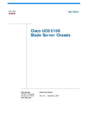
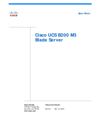
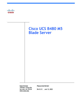
CONFIGURING the SERVERSTEP 3CHOOSE MEMORYThe standard memory features are: Clock speed: Up to 2933 MHz; See available CPUs and their associated DDR4 DIMM maximumclock support in Table 3. Rank per DIMM: 1, 2, 4, or 8 Operational voltage: 1.2 V Registered ECC DDR4 DIMMS (RDIMMs), Load-reduced DIMMs (LRDIMMs), or Intel Optane Persistent Memory Modules (PMem)Memory is organized with six memory channels per CPU, with up to two DIMMs per channel, asshown in Figure 3.Bank 1Bank 2Bank 1B480 M5 Memory OrganizationBank 2Figure 3G1 G2A2 A1Channel AChannel GChannel BChannel HChannel CChannel JChannel DChannel KChannel EChannel LB2 B1H1 H2C2 C1J1 J2D2 D1K1 K2L1 L2E2 E1M1 M2F2 F1Channel MCPU 1CPU 2CPU 3CPU 4Bank 1Bank 2Bank 2Bank 1Channel FN2 N1U1 U2Channel NChannel UP2 P1V1 V2Channel PChannel VChannel QChannel WChannel RChannel XChannel SChannel YChannel TChannel ZQ2 Q1W1 W2R2 R1X1 X2Y1 Y2S2 S1Z1 Z2T2 T1Cisco UCS B480 M5 Blade Server48 DIMMS6 memory channels per CPU2 DIMMs per channel12
CONFIGURING the SERVERSelect DIMMs and Memory MirroringSelect the memory configuration and whether or not you want the memory mirroring option.The available memory DIMMs and mirroring option are listed in Table 5.NOTE: When memory mirroring is enabled, the memory subsystem simultaneouslywrites identical data to two channels. If a memory read from one of the channelsreturns incorrect data due to an uncorrectable memory error, the systemautomatically retrieves the data from the other channel. A transient or soft error inone channel does not affect the mirrored data, and operation continues unless thereis a simultaneous error in exactly the same location on a DIMM and its mirroredDIMM. Memory mirroring reduces the amount of memory available to the operatingsystem by 50% because only one of the two populated channels provides data.Table 5 Available DDR4 DIMMsProduct ID (PID)PID DescriptionVoltageRanks/DIMMUCS-ML-256G8RT-H1256 GB DDR4-2933MHz LRDIMM/8Rx4/1.2v (3DS)1.2 V8UCS-ML-128G4RT-H2128 GB DDR4-2933MHz LRDIMM/4Rx4 (16Gb) (Non-3DS)1.2 V4UCS-ML-X64G4RT-H164 GB DDR4-2933MHz LRDIMM/4Rx4 (8Gb) (Non-3DS)1.2 V4UCS-MR-X64G2RT-H164 GB DDR4-2933MHz RDIMM/2Rx4 (16Gb) (Non-3DS)1.2 V2UCS-MR-X32G2RT-H132GB DDR4-2933MHz RDIMM/2Rx4 (8Gb) (Non-3DS)1.2 V2UCS-MR-X16G1RT-H116 GB DDR4-2933MHz RDIMM/1Rx4 (8Gb) (Non-3DS)1.2 V1UCS-ML-128G4RW3128GB DDR4-3200MHz LRDIMM 4Rx4 (16Gb) (Non-3DS)1.2 V1UCS-MR-X64G2RW264GB DDR4-3200MHz RDIMM 2Rx4 (16Gb) (Non-3DS)1.2 V1UCS-MR-X32G2RW232GB DDR4-3200MHz RDIMM 2Rx4 (8Gb) (Non-3DS)1.2 V1UCS-MR-X16G1RW216GB DDR4-3200MHz RDIMM 1Rx4 (8Gb)(Non-3DS)1.2 V1Intel Optane Persistent Memory ProductUCS-MP-128GS-A0Intel Optane Persistent Memory, 128GB, 2666 MHzUCS-MP-256GS-A0Intel Optane Persistent Memory, 256GB, 2666 MHzUCS-MP-512GS-A0Intel Optane Persistent Memory, 512GB, 2666 MHzIntel Optane Persistent Memory Product Operational ModesUCS-DCPMM-ADApp Direct ModeUCS-DCPMM-MMMemory ModeMemory Mirroring OptionN01-MMIRROR13Memory mirroring optionCisco UCS B480 M5 Blade Server
CONFIGURING the SERVERNotes1. UCS-ML-256G8RT-H is 3DS DIMM and can not be mixed with non-3DS DIMMs2. Cisco announced the End-of-sale of the DDR4-2933 Memory DIMM products: EOL14611 lists the product partnumbers affected by this announcement. Table 6 describes the replacement Memory DIMM product PartNumbers.3. DDR4-3200MHz replacement part numbers will operate at the maximum speed of the Intel 2nd generation XeonScalable processor memory interface, ranging from 2133 MHz to 2933 MHz.Table 6 lists the EOL Memory DIMM product part numbers and their replacement PIDs.Table 6 EOL14611 Memory DIMM Product Part Numbers and their replacement PIDsEOS ProductPart Number (PID)PID DescriptionReplacementProduct PIDReplacement ProductDescriptionUCS-MR-X16G1RT-H16GB DDR4-2933MHz RDIMM1Rx4 (8Gb)/1.2vUCS-MR-X16G1RW16GB DDR4-3200MHz RDIMM1Rx4 (8Gb)/1.2vUCS-MR-X32G2RT-H32GB DDR4-2933MHz RDIMM2Rx4 (8Gb)/1.2vUCS-MR-X32G2RW32GB DDR4-3200MHz RDIMM2Rx4 (8Gb)/1.2vUCS-MR-X64G2RT-H64GB DDR4-2933MHz RDIMM2Rx4 (16Gb)/1.2vUCS-MR-X64G2RW64GB DDR4-3200MHz RDIMM2Rx4 (16Gb)/1.2vUCS-ML-X64G4RT-H64GB DDR4-2933MHzLRDIMM 4Rx4 (8Gb)/1.2vUCS-MR-X64G2RW164GB DDR4-3200MHz RDIMM2Rx4 (16Gb)/1.2vUCS-ML-128G4RT-H128GB DDR4-2933MHzLRDIMM 4Rx4 (16Gb)/1.2vUCS-ML-128G4RW128GB DDR4-3200MHz LRDIMM4Rx4 (16Gb)/1.2vNOTE: (1) Cisco doesn't support a Load Reduce DIMM (LRDIMM) 64GB Memory PID asa replacement PID of existing UCS-ML-x64G4RT-H and recommends migrating to theRegistered DIMM (RDIMM) instead, delivering the best balance in performance andprice.Cisco UCS B480 M5 Blade Server14
DIMM Memory MirroringDIMM Memory MirroringWhen memory mirroring is enabled, the memory subsystem simultaneously writes identical data to twoadjacent channels. If a memory read from one of the channels returns incorrect data due to anuncorrectable memory error, the system automatically retrieves the data from the other channel. Atransient or soft error in one channel does not affect the mirrored data, and operation continues unlessthere is a simultaneous error in exactly the same location on a DIMM and its mirrored DIMM. Memorymirroring reduces the amount of memory available to the operating system by 50% because only one of thetwo populated channels provides data.CPU/Memory Configuration With Memory MirroringSelect from 4, 6, 8, or 12 DIMMs per CPU (DIMMs for all four CPUs must be configured identically). Inaddition, the memory mirroring option (N01-MMIRROR) as shown in Table 5 on page 13 must be selected.The DIMMs will be placed by the factory as shown in the following tables.#DIMMsCPU 1 DIMM Placement in Channels(for identical ranked DIMMs)CPU 2 DIMM Placement in Channels(for identical ranked DIMMs)CPU 1CPU 28(A1,B1); (D1,E1)(G1, H1); (K1, L1)12(A1, B1, C1); (D1, E1, F1)(G1, H1, J1); (K1, L1, M1)16(A1, A2, B1, B2); (D1, D2, E1, E2)(G1, G2, H1, H2); (K1, K2, L1, L2)24(A1, A2, B1, B2, C1, C2); (D1, D2, E1, E2,F1, F2)(G1, G2, H1, H2, J1, J2); (K1, K2, L1, L2, M1,M2)CPU 3 DIMM Placement in Channels(for identical ranked DIMMs)CPU 4 DIMM Placement in Channels(for identical ranked DIMMs)#DIMMsCPU 3CPU 48(N1,P1); (R1,S1)(U1, V1); (X1, Y1)12(N1, P1, Q1); (R1, S1, T1)(U1, V1, W1); (X1, Y1, Z1)16(N1, N2, P1, P2); (R1, R2, S1, S2)(U1, U2, V1, V2); (X1, X2, Y1, Y2)24(N1, N2, P1, P2, Q1, Q2); (R1, R2, S1, S2,T1, T2)(U1, U2, V1, V2, W1, W2); (X1, X2, Y1, Y2,Z1, Z2)NOTE: System performance is optimized when the DIMM type and quantity are equalfor both CPUs, and when all channels are filled equally across the CPUs in the server.15Cisco UCS B480 M5 Blade Server
DIMM Memory MirroringNormal CPU/Memory Configuration (no memory mirroring)Select from 4, 6, 8, or 12 DIMMs per CPU (DIMMs for all four CPUs must be configured identically). TheDIMMs will be placed by the factory as shown in the following tables.#DIMMsCPU 1 DIMM Placement in Channels (for identically ranked DIMMs)4(A1, B1); (D1, E1)6(A1, B1, C1); (D1, E1, F1)8(A1, A2, B1, B2); (D1, D2, E1, E2)12(A1, A2, B1, B2, C1, C2); (D1, D2, E1, E2, F1, F2)#DIMMsCPU 2 DIMM Placement in Channels (for identically ranked DIMMs)4(G1, H1); (K1, L1)6(G1, H1, J1); (K1, L1, M1)8(G1, G2, H1, H2); (K1, K2, L1, L2)12(G1, G2, H1, H2, J1, J2); (K1, K2, L1, L2, M1, M2)#DIMMsCPU 3 DIMM Placement in Channels (for identically ranked DIMMs)4(N1, P1); (R1, S1)6(N1, P1, Q1); (R1, S1, T1)8(N1, N2, P1, P2); (R1, R2, S1, S2)12(N1, N2, P1, P2, Q1, Q2); (R1, R2, S1, S2, T1, T2)#DIMMsCPU 4 DIMM Placement in Channels (for identically ranked DIMMs)4(U1, V1); (X1, Y1)6(U1, V1, W1); (X1, Y1, Z1)8(U1, U2, V1, V2); (Y1, Y2, Z1, Z2)12(U1, U2, V1, V2, W1, W2); (X1, X2, Y1, Y2, Z1, Z2)Cisco UCS B480 M5 Blade Server16
System SpeedsSystem SpeedsMemory will operate at the maximum speed of the Intel Xeon Scalable processor memory controller, rangingfrom 2133 MHz to 2933 MHz for M5 servers. Check CPU specifications for supported speeds.Memory Configurations and ModesDIMM Guidelines System speed is dependent on the CPU DIMM speed support. Refer to Table 5 on page 13 forDIMM Speeds The B480 M5 server supports four different memory reliability, availability, andserviceability (RAS) modes:—Independent Channel Mode—Mirrored Channel Mode—Lockstep Channel Mode—Rank Sparing ModeNOTE: Mixing of Non-Mirrored and Mirrored mode is not allowed. 3DS and non-3DS DIMMs cannot be mixed. Single-rank DIMMs can be mixed with dual-rank DIMMs in the same channel For best performance, observe the following: 17—DIMMs with different timing parameters can be installed on different slots within thesame channel, but only timings that support the slowest DIMM will be applied to all.As a consequence, faster DIMMs will be operated at timings supported by the slowestDIMM populated.—When one DIMM is used, it must be populated in DIMM slot 1 (farthest away from theCPU) of a given channel.—When single or dual rank DIMMs are populated for 2DPC, always populate the highernumber rank DIMM first (starting from the farthest slot). For a 2DPC example, firstpopulate with dual rank DIMMs in the DIMM slot 1. Then single-rank DIMMs in theDIMM 2 slot.DIMMs for all four CPUs must always be configured identically.Cisco UCS B480 M5 Blade Server
System Speeds Cisco memory from previous generation servers (DDR3 and DDR4) is not compatible with UCSB480 M5 Blade.NOTE: System performance is optimized when the DIMM type and quantity are equalfor both CPUs, and when all channels are filled equally across the CPUs in the server. Memory can be configured in any number of DIMMs as pairs, though for optimalperformance, refer to the B480 Memory Guide at Cisco.com.PMem Guidelines PMem require second generation Intel Xeon Scalable Family processors. First generation XeonScalable processors do not support PMem. All installed PMem must be the same size. Mixing PMem of different capacities is not supported. The use of 1Rx8 DIMMs with PMem is not supported.PMem and DIMMs must be populated as shown in Table 7 (6 DIMMs per CPU with 2, 4, or 6 PMem perCPU, as shown). Table 7 2nd Generation Intel Xeon Scalable Processor DIMM and PMem Physical Configurations (quadsocket)DIMMtoPMemCountCPU 1iMC1iMC0Channel 2Channel 1Channel 0Channel 2Channel 1Channel IMMPMemDIMMPMemDIMMDIMMPMemDIMMPMemDIMMF16 to 2DIMM6 to 4DIMMPMemDIMMPMemDIMMDIMMPMemDIMMPMemDIMM6 to 6PMemDIMMtoPMemCountPMemC1CPU 2iMC1iMC0Channel 2Channel 1Channel 0Channel 2Channel 1Channel IMMPMemDIMMPMemDIMMDIMMPMemDIMMPMemDIMMM16 to 2DIMM6 to 4DIMMPMemDIMMPMemDIMMDIMMPMemDIMMPMemDIMM6 to 6PMemCisco UCS B480 M5 Blade ServerPMemJ118
System SpeedsTable 7 2nd Generation Intel Xeon Scalable Processor DIMM and PMem Physical Configurations (quadsocket)DIMMtoPMemCountCPU 3iMC1Channel 2Channel 1T2S2T16 to 2DIMM6 to 4DIMMDIMM6 to 619iMC0PMemS1Channel 0Channel 2Channel IMMPMemDIMMDIMMPMemQ1Channel MCisco UCS B480 M5 Blade Server
System SpeedsTable 7 2nd Generation Intel Xeon Scalable Processor DIMM and PMem Physical Configurations (quadsocket)DIMMtoPMemCountCPU 4iMC1Channel 2Channel 1Channel 0Channel 2Channel 1Channel 0Z2Y2Y1X2W2V2V1U2U1DIMMPMemDIMMDIMMPMemDIMMZ16 to 2DIMM6 to 46 to W1DIMMPMemDIMMPMemDIMMPMemDIMMDIMMPMemDIMMPMemDIMM Either two or four CPUs may be installed when using PMem. For Memory Mode, install a minimum 2 PMem and 6 DIMMs per CPU For App Direct Mode, install a minimum 2 PMem and 6 DIMMs per CPU When either Memory Mode or Mixed Mode is used, the ratio of DIMM capacity to PMemcapacity per CPU must be between 1:16 and 1:2, and the recommended ratio is 1:4 for thebest performance. For example, 6x 16GB DIMMs 2x 256GB PMem is a ratio of 1:5.33(96GB:512GB). In Mixed Mode, the ratio is between memory and only the volatile portion ofthe PMem. This ratio requirement does not apply to App Direct mode. See Table 8 for PMemmemory modes.Table 8 Intel Optane Persistent Memory ModesIntel Optane Persistent Memory ModesApp Direct Mode:PMem operates as a solid-state disk storage device. Data is saved and isnon-volatile. Both PMem and DIMM capacity counts towards CPU tiering(both PMem and DIMM capacities count towards the CPU capacity limit)Memory Mode:1PMem operates as a 100% memory module. Data is volatile and DRAM actsas a cache for PMem. Only PMem capacity counts towards CPU tiering (onlythe PMem capacity counts towards the CPU capacity limit). This is thefactory default mode.Mix Mode:DRAM as cache. Only PMem capacity counts towards CPU tiering (only thePMem capacity counts towards the CPU capacity limit).Notes1. For Memory Mode, the Intel-recommended DIMM to PMem capacity ratio in the same CPU socket is from 1:2 to1:16.For each memory channel with both a PMem and a DIMM installed, the PMem is installed in channelslot 2 (closest) and the DIMM is installed in channel slot 1. To maximize performance, balance all memory channels In configurations with PMem installed, memory mirroring is supported, with two restrictions:Cisco UCS B480 M5 Blade Server20
System Speeds Mirroring is only enabled on the DIMMs installed in the server; the PMem themselves do notsupport mirroring. Only App Direct mode is supported. Memory mirroring cannot be enabled when PMem are inMemory Mode or Mixed Mode.Memory sparing is not supported with PMem installedFor detailed Intel PMem configurations, refer to the following link:Cisco UCS B480 M5 Server Installation GuideFor detailed DIMM/PMem informations, refer toCisco UCS
Cisco UCS B480 M5 Blade Server CONFIGURING the SERVER 6 CONFIGURING the SERVER Follow these steps to configure the Cisco UCS B480 M5 Blade Server: STEP 1 CHOOSE SERVER SKU, page 7 STEP 2 CHOOSE CPU(S), page 8 STEP 3 CHOOSE MEMORY, page 12 STEP 4 CHOOSE OPTIONAL FRONT MEZZANINE: Storage Controller or GPU, page 22