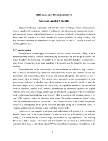
Transcription
RF circuits designGrzegorz BeziukExamples of CAE softwareReferences[1] Ansys Incorporation, Ansoft High Frequency Structure Simulator - tutorials, Ansys,(www.ansoft.com)[2] Kraus G., Ansoft designer SV 2.0 – tutorial fo begginers. Open source document, 2005,(http://www.elektronikschule.de/ krausg/)[3] Altium limited, Altium designer tutorial – getting started with PCB design, Altium ng Started with Altium Designer)[4] Altium limited, Denining and running simulation analises, Altium ng Started with Altium Designer)
IntroductionCircuitparametrsThe steps of circuitdesigning processCalculationsCAD symulation,PCB designingCircuitassemblyCircuitmeasurmentssatisfy ionIntroductionCircuits symulation software:Pspice, Orcad, Multisim (free AD), Altium Designer, Tina (freeTI), SmartSpice, Hspice, T-Spice, Spectre (RF), Eldo (RF),UltraSim, LT Spice (free LT), NanoSim, Nspice, Hsim, B2Spice,ICAD/4, EDSpice,WINecad, TopSpice, Spice Opus, SiMetrix,Micro-capCircuits and EM simulation (RF and microwave): MicrowaveOffice (RF), Ansoft Designer (RF), Sonnet Lite (RF, EMC),Agilent ADS
IntroductionPCB designing software:Altium Designer (Easytrax, Autotrax, Protel), Eagle,Spectra iAllegro (autorouting), CadStar, Orcad, Tina, Circuit Maker, PCad, PCB Elegance, EDWin, VisualPC, BPECS32, ExpertPCB, CirCAD, Layout, McCAD, EPD (RF, hybrid), gEDA (free– linux), ZenitPCB (free), PCB (free), KiCAD (free)Some software contains circuit simulation module and PCBdesigning modulem, for instance Altium Designer.Altium designer – circuits symulationCreate on yourPC folder „.”
Altium designer – circuits symulationAltium designer – circuits symulation
Altium designer – circuits symulationAltium designer – circuits symulation
Altium designer – circuits symulationAltium designer – circuits symulation
Altium designer – circuits symulationAltium designer – circuits symulation
Altium designer – circuits symulationAltium designer – circuits symulation
Altium designer – circuits symulation- add power sources VSRC, set up volatge valuesrequired for Ucc, -Uee- add ports (from menu – Vcc power ports) : GND, Ucc, Uee- add load resistance (R3)- wiring up the circuits- annotate parts- compiling the projectAltium designer – circuits symulation
Altium designer – circuits symulationAltium designer – circuits symulation
Altium designer – PCB designing- add to existing project PCB- save PCB as „.”- replace in the circuit all sources by appropriate ports,- once again annotate schematic (function – update changingslist)- check whether all parts have defined footprints- then use finction – „Design/Update PCB document***.PcbDoc”- define outline of Pcb (by means of Keep out layer) and setoriginAltium designer – PCB designing
Altium designer – PCB designingAltium designer – PCB designing
Altium designer – PCB designingAltium designer – PCB designing
Altium designer – PCB designing- set up all rules- place all components- define new size of Pcb outline- define Pcb clamping points- connect components (one layer board –bottom/top layer, two layers board top andbottom layer)Altium designer – PCB designing
Altium designer – PCB designingAltium designer – PCB designing
Altium designer – PCB designingAnsoft Designer – filter project
Ansoft Designer – filter projectAnsoft Designer – filter project
Ansoft Designer – filter projectAnsoft Designer – filter project
Ansoft Designer – Impedance Matching using a 1 /4 –Microstrip-Line (on a FR4-Board)Ansoft Designer – Impedance Matching using a 1 /4 –Microstrip-Line (on a FR4-Board)
Ansoft Designer – Impedance Matching using a 1 /4 –Microstrip-Line (on a FR4-Board)Ansoft Designer – Impedance Matching using a 1 /4 –Microstrip-Line (on a FR4-Board)
Ansoft Designer – Impedance Matching using a 1 /4 –Microstrip-Line (on a FR4-Board)Ansoft Designer – Impedance Matching using a 1 /4 –Microstrip-Line (on a FR4-Board)Z 0 50 120 77.46Ω
Ansoft Designer – Impedance Matching using a 1 /4 –Microstrip-Line (on a FR4-Board)Ansoft Designer – Impedance Matching using a 1 /4 –Microstrip-Line (on a FR4-Board)
Ansoft Designer – Impedance Matching using a 1 /4 –Microstrip-Line (on a FR4-Board)Ansoft Designer – Impedance Matching using a 1 /4 –Microstrip-Line (on a FR4-Board)
Ansoft Designer – Impedance Matching using a 1 /4 –Microstrip-Line (on a FR4-Board)Ansoft Designer – Impedance Matching using a 1 /4 –Microstrip-Line (on a FR4-Board)
- replace in the circuit all sources by appropriate ports, - once again annotate schematic (function – update changings list) - check whether all parts have defined footprints - then use finction – „Design/Update PCB document ***.PcbDoc” - define outline of Pcb (by means of Ke