Transcription
Modicon M172 Logic ControllerEIO0000002015 09/2018Modicon M172 Logic ControllerHardware Guide(Original tric.com
The information provided in this documentation contains general descriptions and/or technical characteristics of the performance of the products contained herein. This documentation is not intended as asubstitute for and is not to be used for determining suitability or reliability of these products for specific userapplications. It is the duty of any such user or integrator to perform the appropriate and complete riskanalysis, evaluation and testing of the products with respect to the relevant specific application or usethereof. Neither Schneider Electric nor any of its affiliates or subsidiaries shall be responsible or liable formisuse of the information contained herein. If you have any suggestions for improvements or amendmentsor have found errors in this publication, please notify us.You agree not to reproduce, other than for your own personal, noncommercial use, all or part of thisdocument on any medium whatsoever without permission of Schneider Electric, given in writing. You alsoagree not to establish any hypertext links to this document or its content. Schneider Electric does not grantany right or license for the personal and noncommercial use of the document or its content, except for anon-exclusive license to consult it on an "as is" basis, at your own risk. All other rights are reserved.All pertinent state, regional, and local safety regulations must be observed when installing and using thisproduct. For reasons of safety and to help ensure compliance with documented system data, only themanufacturer should perform repairs to components.When devices are used for applications with technical safety requirements, the relevant instructions mustbe followed.Failure to use Schneider Electric software or approved software with our hardware products may result ininjury, harm, or improper operating results.Failure to observe this information can result in injury or equipment damage. 2018 Schneider Electric. All Rights Reserved.2EIO0000002015 09/2018
Table of ContentsSafety Information. . . . . . . . . . . . . . . . . . . . . . . . . . . . . . . . . . . . . . . . . . . .About the Book . . . . . . . . . . . . . . . . . . . . . . . . . . . . . . . . . . . . . . . . . . . . . .Part I Overview. . . . . . . . . . . . . . . . . . . . . . . . . . . . . . . . . . . . . . . . . . . . . .Chapter 1 M172 Range Overview . . . . . . . . . . . . . . . . . . . . . . . . . . . . . . . . . . . . . . . .Modicon M172 Logic Controller Offer Overview . . . . . . . . . . . . . . . . . . . . . . . . . . . . . . . . . .Controller Range Overview . . . . . . . . . . . . . . . . . . . . . . . . . . . . . . . . . . . . . . . . . . . . . . . . . .Expansion Modules Range Overview . . . . . . . . . . . . . . . . . . . . . . . . . . . . . . . . . . . . . . . . . .Communication Modules Range Overview . . . . . . . . . . . . . . . . . . . . . . . . . . . . . . . . . . . . . .Remote Display Range Overview . . . . . . . . . . . . . . . . . . . . . . . . . . . . . . . . . . . . . . . . . . . . .Accessories . . . . . . . . . . . . . . . . . . . . . . . . . . . . . . . . . . . . . . . . . . . . . . . . . . . . . . . . . . . . . .Part II Global Features . . . . . . . . . . . . . . . . . . . . . . . . . . . . . . . . . . . . . . . .Chapter 2 Before Starting . . . . . . . . . . . . . . . . . . . . . . . . . . . . . . . . . . . . . . . . . . . . . .Before Starting. . . . . . . . . . . . . . . . . . . . . . . . . . . . . . . . . . . . . . . . . . . . . . . . . . . . . . . . . . . .Chapter 3 Wiring Best Practices . . . . . . . . . . . . . . . . . . . . . . . . . . . . . . . . . . . . . . . . .Wiring Best Practices . . . . . . . . . . . . . . . . . . . . . . . . . . . . . . . . . . . . . . . . . . . . . . . . . . . . . .Chapter 4 Installation. . . . . . . . . . . . . . . . . . . . . . . . . . . . . . . . . . . . . . . . . . . . . . . . . .TM172 07 / TM172 18 Controllers Mounting Positions . . . . . . . . . . . . . . . . . . . . . . . . .TM172 28 / TM172 42 Controllers Mounting Positions . . . . . . . . . . . . . . . . . . . . . . . .TM172E R Expansion Modules Mounting Positions . . . . . . . . . . . . . . . . . . . . . . . . . . . . . .Controllers and Expansion Modules Clearances. . . . . . . . . . . . . . . . . . . . . . . . . . . . . . . . . .Top Hat Section Rail (DIN Rail) . . . . . . . . . . . . . . . . . . . . . . . . . . . . . . . . . . . . . . . . . . . . . . .Controllers and Expansion Modules Installation . . . . . . . . . . . . . . . . . . . . . . . . . . . . . . . . . .TM172DCLWT Remote Display Installation . . . . . . . . . . . . . . . . . . . . . . . . . . . . . . . . . . . .TM172DCLF Remote Display Installation . . . . . . . . . . . . . . . . . . . . . . . . . . . . . . . . . . . . . .Part III Controllers and Expansion Modules . . . . . . . . . . . . . . . . . . . . . . . . .Chapter 5 Environmental Characteristics . . . . . . . . . . . . . . . . . . . . . . . . . . . . . . . . . .Environmental Characteristics . . . . . . . . . . . . . . . . . . . . . . . . . . . . . . . . . . . . . . . . . . . . . . . .Chapter 6 TM172P / TM172O Controllers Description . . . . . . . . . . . . . . . . .TM172P G07R . . . . . . . . . . . . . . . . . . . . . . . . . . . . . . . . . . . . . . . . . . . . . . . . . . . . . . . . . . .TM172P 18 / TM172O 18 . . . . . . . . . . . . . . . . . . . . . . . . . . . . . . . . . . . . . . . . . . . . . . . .TM172P 28 / TM172O 28R . . . . . . . . . . . . . . . . . . . . . . . . . . . . . . . . . . . . . . . . . . . . . . .TM172P 42 / TM172O 42R . . . . . . . . . . . . . . . . . . . . . . . . . . . . . . . . . . . . . . . . . . . . . . .Chapter 7 TM172E R Expansion Modules Description . . . . . . . . . . . . . . . . . . . . . . .TM172E12R . . . . . . . . . . . . . . . . . . . . . . . . . . . . . . . . . . . . . . . . . . . . . . . . . . . . . . . . . . . . .TM172E28R . . . . . . . . . . . . . . . . . . . . . . . . . . . . . . . . . . . . . . . . . . . . . . . . . . . . . . . . . . . . .Chapter 8 Electrical Characteristics and Wiring Diagrams . . . . . . . . . . . . . . . . . . . . .8.1 Power Supply . . . . . . . . . . . . . . . . . . . . . . . . . . . . . . . . . . . . . . . . . . . . . . . . . . . . . . . . . . . .Power Supply . . . . . . . . . . . . . . . . . . . . . . . . . . . . . . . . . . . . . . . . . . . . . . . . . . . . . . . . . . . .8.2 Digital Input . . . . . . . . . . . . . . . . . . . . . . . . . . . . . . . . . . . . . . . . . . . . . . . . . . . . . . . . . . . . . .Fast Digital Inputs . . . . . . . . . . . . . . . . . . . . . . . . . . . . . . . . . . . . . . . . . . . . . . . . . . . . . . . . .Regular Digital Inputs . . . . . . . . . . . . . . . . . . . . . . . . . . . . . . . . . . . . . . . . . . . . . . . . . . . . . .8.3 Digital Output . . . . . . . . . . . . . . . . . . . . . . . . . . . . . . . . . . . . . . . . . . . . . . . . . . . . . . . . . . . . .High voltage Relay SPST Digital Output . . . . . . . . . . . . . . . . . . . . . . . . . . . . . . . . . . . . . . . .High Voltage Solid-State Relay Digital Output . . . . . . . . . . . . . . . . . . . . . . . . . . . . . . . . . . .High voltage Relay SPDT Digital Output . . . . . . . . . . . . . . . . . . . . . . . . . . . . . . . . . . . . . . . .EIO0000002015 5464951515354565962656668717373767778808183843
8.4 Analog Inputs . . . . . . . . . . . . . . . . . . . . . . . . . . . . . . . . . . . . . . . . . . . . . . . . . . . . . . . . . . . . .Analog Inputs . . . . . . . . . . . . . . . . . . . . . . . . . . . . . . . . . . . . . . . . . . . . . . . . . . . . . . . . . . . . .NTC Analog Input. . . . . . . . . . . . . . . . . . . . . . . . . . . . . . . . . . . . . . . . . . . . . . . . . . . . . . . . . .Resistive Analog Input . . . . . . . . . . . . . . . . . . . . . . . . . . . . . . . . . . . . . . . . . . . . . . . . . . . . . .Current Analog Input . . . . . . . . . . . . . . . . . . . . . . . . . . . . . . . . . . . . . . . . . . . . . . . . . . . . . . .Voltage Analog Input . . . . . . . . . . . . . . . . . . . . . . . . . . . . . . . . . . . . . . . . . . . . . . . . . . . . . . .Analog Input Used as Digital Input. . . . . . . . . . . . . . . . . . . . . . . . . . . . . . . . . . . . . . . . . . . . .8.5 Analog Outputs . . . . . . . . . . . . . . . . . . . . . . . . . . . . . . . . . . . . . . . . . . . . . . . . . . . . . . . . . . .Analog Outputs . . . . . . . . . . . . . . . . . . . . . . . . . . . . . . . . . . . . . . . . . . . . . . . . . . . . . . . . . . .PWM Open Collector Outputs . . . . . . . . . . . . . . . . . . . . . . . . . . . . . . . . . . . . . . . . . . . . . . . .Low Voltage (SELV) Analog Outputs . . . . . . . . . . . . . . . . . . . . . . . . . . . . . . . . . . . . . . . . . . .Analog Current Output . . . . . . . . . . . . . . . . . . . . . . . . . . . . . . . . . . . . . . . . . . . . . . . . . . . . . .Current ON/OFF Current Output . . . . . . . . . . . . . . . . . . . . . . . . . . . . . . . . . . . . . . . . . . . . . .8.6 Communication . . . . . . . . . . . . . . . . . . . . . . . . . . . . . . . . . . . . . . . . . . . . . . . . . . . . . . . . . . .CAN Expansion Bus Port . . . . . . . . . . . . . . . . . . . . . . . . . . . . . . . . . . . . . . . . . . . . . . . . . . . .RS-485 Serial Ports . . . . . . . . . . . . . . . . . . . . . . . . . . . . . . . . . . . . . . . . . . . . . . . . . . . . . . . .USB Serial Ports . . . . . . . . . . . . . . . . . . . . . . . . . . . . . . . . . . . . . . . . . . . . . . . . . . . . . . . . . .Ethernet Port . . . . . . . . . . . . . . . . . . . . . . . . . . . . . . . . . . . . . . . . . . . . . . . . . . . . . . . . . . . . .8.7 Memory . . . . . . . . . . . . . . . . . . . . . . . . . . . . . . . . . . . . . . . . . . . . . . . . . . . . . . . . . . . . . . . . .Memory . . . . . . . . . . . . . . . . . . . . . . . . . . . . . . . . . . . . . . . . . . . . . . . . . . . . . . . . . . . . . . . . .8.8 RTC (Real-Time Clock) . . . . . . . . . . . . . . . . . . . . . . . . . . . . . . . . . . . . . . . . . . . . . . . . . . . . .RTC (Real-Time Clock) . . . . . . . . . . . . . . . . . . . . . . . . . . . . . . . . . . . . . . . . . . . . . . . . . . . . .Chapter 9 User Interface. . . . . . . . . . . . . . . . . . . . . . . . . . . . . . . . . . . . . . . . . . . . . . . .TM172PD / TM172OD User Interface . . . . . . . . . . . . . . . . . . . . . . . . . . . . . . . . . . . .Part IV Remote Display . . . . . . . . . . . . . . . . . . . . . . . . . . . . . . . . . . . . . . . . .Chapter 10 Environmental Characteristics . . . . . . . . . . . . . . . . . . . . . . . . . . . . . . . . . . .Environmental Characteristics . . . . . . . . . . . . . . . . . . . . . . . . . . . . . . . . . . . . . . . . . . . . . . . .Chapter 11 TM172DCL Remote Display Description. . . . . . . . . . . . . . . . . . . . . . . . .TM172DCLWT . . . . . . . . . . . . . . . . . . . . . . . . . . . . . . . . . . . . . . . . . . . . . . . . . . . . . . . . . . .TM172DCLF . . . . . . . . . . . . . . . . . . . . . . . . . . . . . . . . . . . . . . . . . . . . . . . . . . . . . . . . . . . . .Chapter 12 Electrical Characteristics and Wiring Diagrams . . . . . . . . . . . . . . . . . . . . . .Power Supply . . . . . . . . . . . . . . . . . . . . . . . . . . . . . . . . . . . . . . . . . . . . . . . . . . . . . . . . . . . . .Embedded Sensors . . . . . . . . . . . . . . . . . . . . . . . . . . . . . . . . . . . . . . . . . . . . . . . . . . . . . . . .RS-485 Modbus Serial Port . . . . . . . . . . . . . . . . . . . . . . . . . . . . . . . . . . . . . . . . . . . . . . . . . .Part V Parameters. . . . . . . . . . . . . . . . . . . . . . . . . . . . . . . . . . . . . . . . . . . . .Chapter 13 Parameters . . . . . . . . . . . . . . . . . . . . . . . . . . . . . . . . . . . . . . . . . . . . . . . . . .Overview . . . . . . . . . . . . . . . . . . . . . . . . . . . . . . . . . . . . . . . . . . . . . . . . . . . . . . . . . . . . . . . .Controller Parameter Table . . . . . . . . . . . . . . . . . . . . . . . . . . . . . . . . . . . . . . . . . . . . . . . . . .Expansion Module Parameters Table . . . . . . . . . . . . . . . . . . . . . . . . . . . . . . . . . . . . . . . . . .Display Color Touchscreen Parameters Table . . . . . . . . . . . . . . . . . . . . . . . . . . . . . . . . . . .Part VI Commissioning. . . . . . . . . . . . . . . . . . . . . . . . . . . . . . . . . . . . . . . . . .Chapter 14 EcoStruxure Machine Expert - HVAC software (TM171SW) . . . . . . . . . . . .General Description . . . . . . . . . . . . . . . . . . . . . . . . . . . . . . . . . . . . . . . . . . . . . . . . . . . . . . . .Chapter 15 Connection Types . . . . . . . . . . . . . . . . . . . . . . . . . . . . . . . . . . . . . . . . . . . .Connection with a PC Through USB . . . . . . . . . . . . . . . . . . . . . . . . . . . . . . . . . . . . . . . . . . .Connection with a USB Memory Key . . . . . . . . . . . . . . . . . . . . . . . . . . . . . . . . . . . . . . . . . . .Connection with a PC Through Ethernet . . . . . . . . . . . . . . . . . . . . . . . . . . . . . . . . . . . . . . . .Chapter 16 BIOS Update . . . . . . . . . . . . . . . . . . . . . . . . . . . . . . . . . . . . . . . . . . . . . . . .Controller Update BIOS . . . . . . . . . . . . . . . . . . . . . . . . . . . . . . . . . . . . . . . . . . . . . . . . . . . . .Appendices . . . . . . . . . . . . . . . . . . . . . . . . . . . . . . . . . . . . . . . . . . . . . . . . . . . . . 02015 09/2018
Appendix A Appendices . . . . . . . . . . . . . . . . . . . . . . . . . . . . . . . . . . . . . . . . . . . . . . . . .NTC 10k beta 3435 Resistance Temperature Table . . . . . . . . . . . . . . . . . . . . . . . . . . . . . . .NTC 10k-2 beta (25/50) 3977 Resistance Temperature Table . . . . . . . . . . . . . . . . . . . . . . .Pt1000 Resistance Temperature Table . . . . . . . . . . . . . . . . . . . . . . . . . . . . . . . . . . . . . . . . .GlossaryIndexEIO0000002015 09/2018.1731741761781831875
6EIO0000002015 09/2018
Safety InformationImportant InformationNOTICERead these instructions carefully, and look at the equipment to become familiar with the device beforetrying to install, operate, service, or maintain it. The following special messages may appear throughoutthis documentation or on the equipment to warn of potential hazards or to call attention to information thatclarifies or simplifies a procedure.PLEASE NOTEElectrical equipment should be installed, operated, serviced, and maintained only by qualified personnel.No responsibility is assumed by Schneider Electric for any consequences arising out of the use of thismaterial.A qualified person is one who has skills and knowledge related to the construction and operation ofelectrical equipment and its installation, and has received safety training to recognize and avoid thehazards involved.Qualification of PersonnelOnly appropriately trained persons who are familiar with and understand the contents of this manual andall other pertinent product documentation are authorized to work on and with this product.The qualified person must be able to detect possible hazards that may arise from parameterization,modifying parameter values and generally from mechanical, electrical, or electronic equipment. Thequalified person must be familiar with the standards, provisions, and regulations for the prevention ofindustrial accidents, which they must observe when designing and implementing the system.EIO0000002015 09/20187
Intended UseThe products described or affected by this document, together with software, accessories, and options, arecontrollers, intended for commercial HVAC machines according to the instructions, directions, examples,and safety information contained in the present document and other supporting documentation.The product may only be used in compliance with all applicable safety regulations and directives, thespecified requirements, and the technical data.Prior to using the product, you must perform a risk assessment in view of the planned application. Basedon the results, the appropriate safety-related measures must be implemented.Since the product is used as a component in an overall machine or process, you must ensure the safetyof persons by means of the design of this overall system.Operate the product only with the specified cables and accessories. Use only genuine accessories andspare parts.Any use other than the use explicitly permitted is prohibited and can result in unanticipated hazards.Prohibited UseAny use other than that expressed above under Permitted use is strictly prohibited.The relay contacts supplied are of an electromechanical type and subject to wear. Functional safetyprotection devices, specified in international or local standards, must be installed externally to this device.Liability and Residual RisksThe liability of Schneider Electric is limited to the proper and professional use of this product under theguidelines contained in the present and other supporting documents, and does not extend to damagescaused by (but not limited to): Unspecified installation/use and, in particular, in contravention of the safety requirements of establishedlegislation or specified in this document; Use on equipment which does not provide adequate protection against electrocution, water and dust inthe actual installation conditions; Use on equipment in which dangerous components can be accessed without the use of specific tools; Installation/use on equipment which does not comply with established legislation and standards.DisposalThe appliance (or the product) must be disposed of separately in compliance with the local standards inforce on waste disposal.8EIO0000002015 09/2018
About the BookAt a GlanceDocument ScopeThis document describes the Modicon M172 Logic controllers, expansion modules, remote displays, andaccessories, including installation and wiring information.NOTE: Read and understand this document and all related documents (see page 9) before installing,operating, or maintaining your controller.Validity NoteThis document has been updated for the release of EcoStruxure Machine Expert - HVAC V1.0.For product compliance and environmental information (RoHS, REACH, PEP, EOLI, etc.), go towww.schneider-electric.com/green-premium.The technical characteristics of the devices described in the present document also appear online. Toaccess the information online:StepAction1Go to the Schneider Electric home page www.schneider-electric.com.2In the Search box type the reference of a product or the name of a product range. Do not include blank spaces in the reference or product range. To get information on grouping similar modules, use asterisks (*).3If you entered a reference, go to the Product Datasheets search results and click on thereference that interests you.If you entered the name of a product range, go to the Product Ranges search results and clickon the product range that interests you.4If more than one reference appears in the Products search results, click on the reference thatinterests you.5Depending on the size of your screen, you may need to scroll down to see the data sheet.6To save or print a data sheet as a .pdf file, click Download XXX product datasheet.The characteristics that are presented in the present document should be the same as those characteristics that appear online. In line with our policy of constant improvement, we may revise content over timeto improve clarity and accuracy. If you see a difference between the document and online information, usethe online information as your reference.Related DocumentsTitle of documentationReference numberEcoStruxure Machine Expert - HVAC software - Operating GuideEIO0000003412 (ENG)TM172 Optimized & Performance 7/18 IO Instruction SheetQGH90428TM172 Performance 28/42 IO Instruction SheetNHA87740TM172 Optimized & Performance Isolated 28/42 IO Instruction SheetPHA83703TM172 Optimized & Performance Expansion 12/28 IO Instruction SheetQGH26895TM172DCLW Display Color Touchscreen Instruction SheetQGH26896TM172DCLF Display Color Touchscreen Flush Mounting Instruction SheetPHA38669You can download these technical publications and other technical information from our website 2015 09/20189
Product Related InformationDANGERHAZARD OF ELECTRIC SHOCK, EXPLOSION OR ARC FLASH Disconnect all power from all equipment including connected devices prior to removing any covers ordoors, or installing or removing any accessories, hardware, cables, or wires except under the specificconditions specified in the appropriate hardware guide for this equipment.Always use a properly rated voltage sensing device to confirm the power is off where and whenindicated.Replace and secure all covers, accessories, hardware, cables, and wires and confirm that a properground connection exists before applying power to the unit.Use only the specified voltage when operating this equipment and any associated products.Failure to follow these instructions will result in death or serious injury.This equipment has been designed to operate outside of any hazardous location, and exclusive ofapplications that generate, or have the potential to generate, hazardous atmospheres. Only install thisequipment in zones known to be free, at all times, of hazardous atmospheres.DANGERPOTENTIAL FOR EXPLOSION Install and use this equipment in non-hazardous locations only.Do not install and use this equipment in applications capable of generating hazardous atmospheres,such as those applications employing flammable refrigerants.Failure to follow these instructions will result in death or serious injury.For information concerning the use of control equipment in applications capable of generating hazardousmaterials, consult your local, regional, or national standards bureau or certification agency.WARNINGLOSS OF CONTROL The designer of any control scheme must consider the potential failure modes of control paths and,for certain critical control functions, provide a means to achieve a safe state during and after a pathfailure. Examples of critical control functions are emergency stop and overtravel stop, power outageand restart.Separate or redundant control paths must be provided for critical control functions.System control paths may include communication links. Consideration must be given to theimplications of unanticipated transmission delays or failures of the link.Observe all accident prevention regulations and local safety guidelines.1Each implementation of this equipment must be individually and thoroughly tested for proper operationbefore being placed into service.Failure to follow these instructions can result in death, serious injury, or equipment damage.1For additional information, refer to NEMA ICS 1.1 (latest edition), "Safety Guidelines for the Application,Installation, and Maintenance of Solid State Control" and to NEMA ICS 7.1 (latest edition), "SafetyStandards for Construction and Guide for Selection, Installation and Operation of Adjustable-Speed DriveSystems" or their equivalent governing your particular location.WARNINGUNINTENDED EQUIPMENT OPERATION Only use software approved by Schneider Electric for use with this equipment.Update your application program every time you change the physical hardware configuration.Failure to follow these instructions can result in death, serious injury, or equipment damage.10EIO0000002015 09/2018
Terminology Derived from StandardsThe technical terms, terminology, symbols and the corresponding descriptions in this manual, or thatappear in or on the products themselves, are generally derived from the terms or definitions of internationalstandards.In the area of functional safety systems, drives and general automation, this may include, but is not limitedto, terms such as safety, safety function, safe state, fault, fault reset, malfunction, failure, error, errormessage, dangerous, etc.Among others, these standards include:StandardDescriptionEN 61131-2:2007Programmable controllers, part 2: Equipment requirements and tests.ISO 13849-1:2008Safety of machinery: Safety related parts of control systems.General principles for design.EN 61496-1:2013Safety of machinery: Electro-sensitive protective equipment.Part 1: General requirements and tests.ISO 12100:2010Safety of machinery - General principles for design - Risk assessment and riskreductionEN 60204-1:2006Safety of machinery - Electrical equipment of machines - Part 1: GeneralrequirementsEN 1088:2008ISO 14119:2013Safety of machinery - Interlocking devices associated with guards - Principlesfor design and selectionISO 13850:2006Safety of machinery - Emergency stop - Principles for designEN/IEC 62061:2005Safety of machinery - Functional safety of safety-related electrical, electronic,and electronic programmable control systemsIEC 61508-1:2010Functional safety of electrical/electronic/programmable electronic safetyrelated systems: General requirements.IEC 61508-2:2010Functional safety of electrical/electronic/programmable electronic safetyrelated systems: Requirements for electrical/electronic/programmableelectronic safety-related systems.IEC 61508-3:2010Functional safety of electrical/electronic/programmable electronic safetyrelated systems: Software requirements.IEC 61784-3:2008Digital data communication for measurement and control: Functional safetyfield buses.2006/42/ECMachinery Directive2014/30/EUElectromagnetic Compatibility Directive2014/35/EULow Voltage DirectiveIn addition, terms used in the present document may tangentially be used as they are derived from otherstandards such as:StandardDescriptionIEC 60034 seriesRotating electrical machinesIEC 61800 seriesAdjustable speed electrical power drive systemsIEC 61158 seriesDigital data communications for measurement and control – Fieldbus for use inindustrial control systemsFinally, the term zone of operation may be used in conjunction with the description of specific hazards, andis defined as it is for a hazard zone or danger zone in the Machinery Directive (2006/42/EC) andISO 12100:2010.NOTE: The aforementioned standards may or may not apply to the specific products cited in the presentdocumentation. For more information concerning the individual standards applicable to the productsdescribed herein, see the characteristics tables for those product references.EIO0000002015 09/201811
12EIO0000002015 09/2018
Modicon M172 Logic ControllerOverviewEIO0000002015 09/2018Part IOverviewOverviewEIO0000002015 09/201813
Overview14EIO0000002015 09/2018
Modicon M172 Logic ControllerM172 Range OverviewEIO0000002015 09/2018Chapter 1M172 Range OverviewM172 Range OverviewWhat Is in This Chapter?This chapter contains the following topics:TopicEIO0000002015 09/2018PageModicon M172 Logic Controller Offer Overview16Controller Range Overview17Expansion Modules Range Overview19Communication Modules Range Overview20Remote Display Range Overview21Accessories2315
M172 Range OverviewModicon M172 Logic Controller Offer OverviewGeneral DescriptionModicon M172 Logic Controller are suitable for customized applications designed to control simple orcomplex machines: Air/water-cooled chiller Rooftop unit Heat pump Compressor rack Ventilation unitThe M172 offer is made of:Controllers (see page 17) Expansion modules (see page 19) Communication modules (see page 20) Remote displays (see page 21) Accessories (see page 23) Programming SoftwareIn association with the controllers hardware, the EcoStruxure Machine Expert - HVAC (TM171SW)development tool is available to program and customize applications.You can download EcoStruxure Machine Expert - HVAC - Programming Software for Modicon M171M172 Logic Controllers from Schneider-electric web site download center.The use of several programming languages in accordance with IEC 61131-3 regulations (programmingstandard for industrial control), makes it possible to develop new algorithms or entire programs easily,which can then be uploaded to the M172 controllers via a PC and a Programming cable, helping to provideconfidentiality with appropriate security.For mode information, refer to Connection Types (see page 165).16EIO0000002015 09/2018
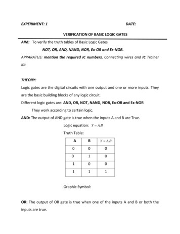
M172 Range OverviewController Range OverviewType CodeController type code:Type code descriptionTM172PDG42RTM172Product familyTM172Complementaryproduct familyPDG42RIP PerformanceO OptimizedPhysical featureB BlindD Built-in DisplayEmbeddedCommunicationG RS-485 and Ethernet based communicationprotocolsM RS-485 based communication protocolsNumber of I/O7182842Digital output typeR RelaysS Solid State Relays(SSR) and RelaysPower supplyisolation (1)I PowerSupplyIsolated(1) Only for 28 and 42 I/OControllers ReferencesDIDOAIAO2 RS-4851 Ethernet1 CAN Exp. busCommunicationUSB Mini-BUSBUSB AInputs/OutputsMicro SD cardComplementaryproduct familyDisplayReference2320 2682 7 Inputs/Outputs (see page 54)TM172PBG07RPerformanceTM172PDG07R 18 Inputs/Outputs (see page 56)TM172PBG18RPerformanceTM172PDG18R TM172PDG18STM172OBM18R4 2 SSROptimizedTM172ODM18R-2682-- - 8884 84-- - 28 Inputs/Outputs (see page 59)TM172PBG28RPerformance-TM172PBG28RITM172PDG28R TM172PDG28RITM172PDG28S6 2 SSRTM172PDG28SITM172OBM28RTM172ODM28REIO0000002015 09/2018Optimized-88 17
M172 Range OverviewDIDOAIAO2 RS-4851 Ethernet1 CAN Exp. busCommunicationUSB Mini-BUSBUSB AInputs/OutputsMicro SD cardComplementaryprodu
This document describes the Modicon M172 Logic controllers, expansion modules, remote displays, and accessories, including installation and wiring information. NOTE: Read and understand this document and all related documents (seepage9) before installing, operating, or ma