Transcription
Modicon M221EIO0000001360 04/2014Modicon M221Logic ControllerProgramming .com
The information provided in this documentation contains general descriptions and/or technicalcharacteristics of the performance of the products contained herein. This documentation is notintended as a substitute for and is not to be used for determining suitability or reliability of theseproducts for specific user applications. It is the duty of any such user or integrator to perform theappropriate and complete risk analysis, evaluation and testing of the products with respect to therelevant specific application or use thereof. Neither Schneider Electric nor any of its affiliates orsubsidiaries shall be responsible or liable for misuse of the information contained herein. If youhave any suggestions for improvements or amendments or have found errors in this publication,please notify us.No part of this document may be reproduced in any form or by any means, electronic ormechanical, including photocopying, without express written permission of Schneider Electric.All pertinent state, regional, and local safety regulations must be observed when installing andusing this product. For reasons of safety and to help ensure compliance with documented systemdata, only the manufacturer should perform repairs to components.When devices are used for applications with technical safety requirements, the relevantinstructions must be followed.Failure to use Schneider Electric software or approved software with our hardware products mayresult in injury, harm, or improper operating results.Failure to observe this information can result in injury or equipment damage. 2014 Schneider Electric. All rights reserved.2EIO0000001360 04/2014
Table of ContentsSafety Information . . . . . . . . . . . . . . . . . . . . . . . . . . . . .About the Book. . . . . . . . . . . . . . . . . . . . . . . . . . . . . . . .Part I Introduction. . . . . . . . . . . . . . . . . . . . . . . . . . . . . . .Chapter 1 About the Modicon M221 Logic Controller . . . . . . . . .TM221C Logic Controller Description . . . . . . . . . . . . . . . . . . . . . . . . .TM221M Logic Controller Description . . . . . . . . . . . . . . . . . . . . . . . . .Chapter 2 Configuration Features . . . . . . . . . . . . . . . . . . . . . . . . .2.1 Objects . . . . . . . . . . . . . . . . . . . . . . . . . . . . . . . . . . . . . . . . . . . . . . . .Objects . . . . . . . . . . . . . . . . . . . . . . . . . . . . . . . . . . . . . . . . . . . . . . . .Object Types . . . . . . . . . . . . . . . . . . . . . . . . . . . . . . . . . . . . . . . . . . . .Addressing I/O Objects . . . . . . . . . . . . . . . . . . . . . . . . . . . . . . . . . . . .Maximum Number of Objects . . . . . . . . . . . . . . . . . . . . . . . . . . . . . . .2.2 Task Structure . . . . . . . . . . . . . . . . . . . . . . . . . . . . . . . . . . . . . . . . . . .Tasks and Scan Modes . . . . . . . . . . . . . . . . . . . . . . . . . . . . . . . . . . . .Maximum Number of Tasks and Priorities. . . . . . . . . . . . . . . . . . . . . .2.3 Controller States and Behaviors . . . . . . . . . . . . . . . . . . . . . . . . . . . . .Controller State Diagram . . . . . . . . . . . . . . . . . . . . . . . . . . . . . . . . . . .Controller States Description. . . . . . . . . . . . . . . . . . . . . . . . . . . . . . . .Controller State Transitions . . . . . . . . . . . . . . . . . . . . . . . . . . . . . . . . .Persistent Variables. . . . . . . . . . . . . . . . . . . . . . . . . . . . . . . . . . . . . . .Output Behavior. . . . . . . . . . . . . . . . . . . . . . . . . . . . . . . . . . . . . . . . . .Part II Configuring the M221 Logic Controller . . . . . . . .Chapter 3 How to Configure a Controller . . . . . . . . . . . . . . . . . . .Building a Configuration . . . . . . . . . . . . . . . . . . . . . . . . . . . . . . . . . . .Configuring the M221 Logic Controller . . . . . . . . . . . . . . . . . . . . . . . .Downloading Firmware Updates with an SD Card . . . . . . . . . . . . . . .Updating Firmware using Executive Loader Wizard . . . . . . . . . . . . . .Chapter 4 Embedded Input/Output Configuration . . . . . . . . . . . .Configuring Digital Inputs . . . . . . . . . . . . . . . . . . . . . . . . . . . . . . . . . .Configuring Digital Outputs . . . . . . . . . . . . . . . . . . . . . . . . . . . . . . . . .Configuring Analog Inputs . . . . . . . . . . . . . . . . . . . . . . . . . . . . . . . . . .Configuring High Speed Counters . . . . . . . . . . . . . . . . . . . . . . . . . . . .Configuring Pulse Generators . . . . . . . . . . . . . . . . . . . . . . . . . . . . . . .EIO0000001360 3545960616364687072803
Chapter 5 I/O Bus Configuration . . . . . . . . . . . . . . . . . . . . . . . . . .I/O Configuration General Practices . . . . . . . . . . . . . . . . . . . . . . . . . .Maximum Hardware Configuration. . . . . . . . . . . . . . . . . . . . . . . . . . . .Configuring Cartridges and Expansion Modules . . . . . . . . . . . . . . . . .Chapter 6 Embedded Communication Configuration . . . . . . . . .6.1 Ethernet Configuration . . . . . . . . . . . . . . . . . . . . . . . . . . . . . . . . . . . . .Configuring Ethernet Network . . . . . . . . . . . . . . . . . . . . . . . . . . . . . . .Configuring Modbus TCP. . . . . . . . . . . . . . . . . . . . . . . . . . . . . . . . . . .6.2 Serial Line Configuration . . . . . . . . . . . . . . . . . . . . . . . . . . . . . . . . . . .Configuring Serial Line. . . . . . . . . . . . . . . . . . . . . . . . . . . . . . . . . . . . .Part III Programming the M221 Logic Controller . . . . . .Chapter 7 How to Use the Source Code Examples . . . . . . . . . . .How to Use the Source Code Examples . . . . . . . . . . . . . . . . . . . . . . .Chapter 8 I/O Objects . . . . . . . . . . . . . . . . . . . . . . . . . . . . . . . . . . .Digital Inputs (%I). . . . . . . . . . . . . . . . . . . . . . . . . . . . . . . . . . . . . . . . .Digital Outputs (%Q) . . . . . . . . . . . . . . . . . . . . . . . . . . . . . . . . . . . . . .Analog Inputs (%IW) . . . . . . . . . . . . . . . . . . . . . . . . . . . . . . . . . . . . . .Analog Outputs (%QW) . . . . . . . . . . . . . . . . . . . . . . . . . . . . . . . . . . . .Chapter 9 Function Blocks . . . . . . . . . . . . . . . . . . . . . . . . . . . . . . .9.1 Fast Counter (%FC) . . . . . . . . . . . . . . . . . . . . . . . . . . . . . . . . . . . . . . .Description . . . . . . . . . . . . . . . . . . . . . . . . . . . . . . . . . . . . . . . . . . . . . .Configuration . . . . . . . . . . . . . . . . . . . . . . . . . . . . . . . . . . . . . . . . . . . .Programming Example. . . . . . . . . . . . . . . . . . . . . . . . . . . . . . . . . . . . .9.2 High Speed Counter (%HSC) . . . . . . . . . . . . . . . . . . . . . . . . . . . . . . .Description . . . . . . . . . . . . . . . . . . . . . . . . . . . . . . . . . . . . . . . . . . . . . .Configuration . . . . . . . . . . . . . . . . . . . . . . . . . . . . . . . . . . . . . . . . . . . .High Speed Counter in Counting Mode . . . . . . . . . . . . . . . . . . . . . . . .High Speed Counter in Frequency Meter Mode. . . . . . . . . . . . . . . . . .9.3 Pulse (%PLS). . . . . . . . . . . . . . . . . . . . . . . . . . . . . . . . . . . . . . . . . . . .Description . . . . . . . . . . . . . . . . . . . . . . . . . . . . . . . . . . . . . . . . . . . . . .Configuration . . . . . . . . . . . . . . . . . . . . . . . . . . . . . . . . . . . . . . . . . . . .Programming Example. . . . . . . . . . . . . . . . . . . . . . . . . . . . . . . . . . . . .9.4 Pulse Width Modulation (%PWM) . . . . . . . . . . . . . . . . . . . . . . . . . . . .Description . . . . . . . . . . . . . . . . . . . . . . . . . . . . . . . . . . . . . . . . . . . . . .Configuration . . . . . . . . . . . . . . . . . . . . . . . . . . . . . . . . . . . . . . . . . . . .Programming Example. . . . . . . . . . . . . . . . . . . . . . . . . . . . . . . . . . . . EIO0000001360 04/2014
Chapter 10 System Objects. . . . . . . . . . . . . . . . . . . . . . . . . . . . . . . .System Bits (%S). . . . . . . . . . . . . . . . . . . . . . . . . . . . . . . . . . . . . . . . .System Words (%SW) . . . . . . . . . . . . . . . . . . . . . . . . . . . . . . . . . . . . .GlossaryIndexEIO0000001360 04/2014.1491501581751795
6EIO0000001360 04/2014
Safety InformationImportant InformationNOTICERead these instructions carefully, and look at the equipment to become familiar with the devicebefore trying to install, operate, or maintain it. The following special messages may appearthroughout this documentation or on the equipment to warn of potential hazards or to call attentionto information that clarifies or simplifies a procedure.EIO0000001360 04/20147
PLEASE NOTEElectrical equipment should be installed, operated, serviced, and maintained only by qualifiedpersonnel. No responsibility is assumed by Schneider Electric for any consequences arising out ofthe use of this material.A qualified person is one who has skills and knowledge related to the construction and operationof electrical equipment and its installation, and has received safety training to recognize and avoidthe hazards involved.8EIO0000001360 04/2014
About the BookAt a GlanceDocument ScopeThis document describes the configuration and programming of the Modicon M221 LogicController for SoMachine Basic. For further information, refer to the separate documents providedin the SoMachine Basic online help.Validity NoteThis document has been updated with the release of SoMachine Basic V1.1.Related DocumentsTitle of DocumentationReference NumberSoMachine Basic - Operating GuideEIO0000001354 (ENG)EIO0000001355 (FRA)EIO0000001356 (GER)EIO0000001357 (SPA)EIO0000001358 (ITA)EIO0000001359 (CHS)EIO0000001366 (POR)EIO0000001367 (TUR)SoMachine Basic Generic Functions - Library GuideEIO0000001474 (ENG)EIO0000001475 (FRA)EIO0000001476(GER)EIO0000001477 (SPA)EIO0000001478 (ITA)EIO0000001479 (CHS)EIO0000001480 (POR)EIO0000001481 (TUR)Modicon M221 Logic Controller - Hardware GuideEIO0000001384 (ENG)EIO0000001385 (FRA)EIO0000001386 (GER)EIO0000001387 (SPA)EIO0000001388 (ITA)EIO0000001389 (CHS)EIO0000001370 (POR)EIO0000001371 (TUR)EIO0000001360 04/20149
10Title of DocumentationReference NumberModicon TMC2 Cartridge - Programming GuideEIO0000001782 (ENG)EIO0000001783 (FRA)EIO0000001784 (GER)EIO0000001785 (SPA)EIO0000001786 (ITA)EIO0000001787 (CHS)EIO0000001788 (POR)EIO0000001789 (TUR)Modicon TMC2 Cartridge - Hardware GuideEIO0000001768 (ENG)EIO0000001769 (FRE)EIO0000001770 (GER)EIO0000001771 (SPA)EIO0000001772 (ITA)EIO0000001773 (CHS)EIO0000001775 (TUR)EIO0000001774 (POR)Modicon TM3 Expansion Modules Configuration - ProgrammingGuideEIO0000001396 (ENG)EIO0000001397 (FRA)EIO0000001398 (GER)EIO0000001399 (SPA)EIO0000001400 (ITA)EIO0000001401 (CHS)EIO0000001374 (POR)EIO0000001375 (TUR)Modicon TM3 Digital I/O Modules - Hardware GuideEIO0000001408 (ENG)EIO0000001409 (FRA)EIO0000001410 (GER)EIO0000001411 (SPA)EIO0000001412 (ITA)EIO0000001413 (CHS)EIO0000001376 (POR)EIO0000001377 (TUR)Modicon TM3 Analog I/O Modules - Hardware GuideEIO0000001414 (ENG)EIO0000001415 (FRA)EIO0000001416 (GER)EIO0000001417 (SPA)EIO0000001418 (ITA)EIO0000001419 (CHS)EIO0000001378 (POR)EIO0000001379 (TUR)EIO0000001360 04/2014
Title of DocumentationReference NumberModicon TM3 Expert Modules - Hardware GuideEIO0000001420 (ENG)EIO0000001421 (FRA)EIO0000001422 (GER)EIO0000001423 (SPA)EIO0000001424 (ITA)EIO0000001425 (CHS)EIO0000001380 (POR)EIO0000001381 (TUR)Modicon TM3 Transmitter and Receiver Modules - Hardware GuideEIO0000001426 (ENG)EIO0000001427 (FRA)EIO0000001428 (GER)EIO0000001429 (SPA)EIO0000001430 (ITA)EIO0000001431 (CHS)EIO0000001382 (POR)EIO0000001383 (TUR)Modicon TM2 Expansion Modules Configuration - ProgrammingGuideEIO0000000396 (ENG)EIO0000000397 (FRE)EIO0000000398 (GER)EIO0000000399 (SPA)EIO0000000400 (ITA)EIO0000000401 (CHS)Modicon TM2 Digital I/O Modules - Hardware GuideEIO0000000028 (ENG)EIO0000000029 (FRA)EIO0000000030 (GER)EIO0000000031 (SPA)EIO0000000032 (ITA)EIO0000000033 (CHS)Modicon TM2 Analog I/O Modules - Hardware GuideEIO0000000034 (ENG)EIO0000000035 (FRA)EIO0000000036 (GER)EIO0000000037 (SPA)EIO0000000038 (ITA)EIO0000000039 (CHS)You can download these technical publications and other technical information from our websiteat www.schneider-electric.com.EIO0000001360 04/201411
Product Related InformationWARNINGLOSS OF CONTROLzzzzzThe designer of any control scheme must consider the potential failure modes of control pathsand, for certain critical control functions, provide a means to achieve a safe state during andafter a path failure. Examples of critical control functions are emergency stop and overtravelstop, power outage and restart.Separate or redundant control paths must be provided for critical control functions.System control paths may include communication links. Consideration must be given to theimplications of unanticipated transmission delays or failures of the link.Observe all accident prevention regulations and local safety guidelines.1Each implementation of this equipment must be individually and thoroughly tested for properoperation before being placed into service.Failure to follow these instructions can result in death, serious injury, or equipmentdamage.1For additional information, refer to NEMA ICS 1.1 (latest edition), "Safety Guidelines for theApplication, Installation, and Maintenance of Solid State Control" and to NEMA ICS 7.1 (latestedition), "Safety Standards for Construction and Guide for Selection, Installation and Operation ofAdjustable-Speed Drive Systems" or their equivalent governing your particular location.WARNINGUNINTENDED EQUIPMENT OPERATIONzzOnly use software approved by Schneider Electric for use with this equipment.Update your application program every time you change the physical hardware configuration.Failure to follow these instructions can result in death, serious injury, or equipmentdamage.12EIO0000001360 04/2014
Modicon M221IntroductionEIO0000001360 04/2014IntroductionPart IIntroductionOverviewThis part provides general information about the Modicon M221 Logic Controller and itsconfiguration and programming features.What Is in This Part?This part contains the following chapters:ChapterChapter NamePage1About the Modicon M221 Logic Controller152Configuration Features25EIO0000001360 04/201413
Introduction14EIO0000001360 04/2014
Modicon M221About the Modicon M221 Logic ControllerEIO0000001360 04/2014About the Modicon M221 Logic ControllerChapter 1About the Modicon M221 Logic ControllerWhat Is in This Chapter?This chapter contains the following topics:TopicPageTM221C Logic Controller Description16TM221M Logic Controller Description20EIO0000001360 04/201415
About the Modicon M221 Logic ControllerTM221C Logic Controller DescriptionOverviewThe TM221C Logic Controller has various powerful features and can service a wide range ofapplications.Software configuration, programming, and commissioning are accomplished with the SoMachineBasic software described in the SoMachine Basic Operating Guide and the M221 Logic Controller- Programming Guide.Programming LanguagesThe M221 Logic Controller is configured and programmed with the SoMachine Basic software,which supports the following IEC 61131-3 programming languages:z IL: Instruction Listz LD: Ladder Diagramz Grafcet (List)Power SupplyThe power supply of the TM221C Logic Controller is 24 Vdc or 100.240 Vac.Real Time ClockThe M221 Logic Controller includes a Real Time Clock (RTC) system.Run/StopThe M221 Logic Controller can be operated externally by the following:z a hardware Run/Stop switchz a Run/Stop operation by a dedicated digital input, defined in the software configuration (for moreinformation, refer to Configuring Digital Inputs (see page 64).)z SoMachine Basic software (for more information, refer to Toolbar (see SoMachine Basic,Operating Guide)).MemoryThis table describes the different types of memory:16Memory TypeSizeUsed toRAM512 Kbyte, of which 256 Kbyte availablefor the application.execute the application and contain dataFlash1.5 Mbyte, of which 256 Kbyte is used tobackup the user application and data incase of power outage.save the applicationEIO0000001360 04/2014
About the Modicon M221 Logic ControllerEmbedded Inputs/OutputsThe following embedded I/O types are available, depending on the controller reference:Regular inputsz Fast inputs associated with countersz Regular sink/source transistor outputsz Fast sink/source transistor outputs associated with pulse generatorsz Relay outputsz Analog inputsz Analog outputszRemovable StorageThe M221 Logic Controllers include an embedded SD card slot.The main uses of the SD card are:Initializing the controller with a new applicationz Updating the controller firmwarezEmbedded Communication FeaturesThe following types of communication ports are available depending on the controller reference:Ethernetz USB Mini-Bz Serial Line 1zTM221C Logic ControllersReferenceDigital InputsDigital OutputsAnalog CommunicationInputs PortsTM221C16R5 regular inputs(1)4 fast inputs7 relay outputsYes100.240 Vac1 serial line port1 USB programmingportYes1 serial line port1 USB programmingport1 Ethernet port(HSC)(2)TM221CE16RPower SupplyNOTE: All TM221C Logic Controller logic controllers use removable screw terminal blocks.(1) The regular inputs have a maximum frequency of 5 kHz.(2) The fast inputs can be used either as regular inputs or as fast inputs for counting or event functions.(3) The fast transistor outputs can be used either as regular transistor outputs, or for PWM, PLS functions,or reflex outputs for HSC.EIO0000001360 04/201417
About the Modicon M221 Logic ControllerReferenceDigital InputsDigital OutputsAnalog CommunicationInputs PortsTM221C16T5 regular inputs(1)4 fast inputsSource outputs5 regulartransistoroutputs2 fast outputsYes24 Vdc1 serial line port1 USB programmingportYes1 serial line port1 USB programmingport1 Ethernet portYes100.240 Vac1 serial line port1 USB programmingportYes1 serial line port1 USB programmingport1 Ethernet portYes24 Vdc1 serial line port1 USB programmingportYes1 serial line port1 USB programmingport1 Ethernet portYes100.240 Vac1 serial line port1 USB programmingportYes1 serial line port1 USB programmingport1 Ethernet portYes24 Vdc1 serial line port1 USB programmingportYes1 serial line port1 USB programmingport1 Ethernet port(HSC)(2)TM221CE16T(PWM/PLS)(3)TM221C24R10 regular inputs(1) 10 relay outputs4 fast inputs(HSC)(2)TM221CE24RTM221C24TSource outputs8 regulartransistoroutputs2 fast outputsTM221CE24T(PWM/PLS)(3)TM221C40R20 regular inputs(1) 16 relay outputs4 fast inputs(HSC)(2)TM221CE40RTM221C40TTM221CE40TSource outputs14 regulartransistoroutputs2 fast outputs(PWM/PLS)(3)Power SupplyNOTE: All TM221C Logic Controller logic controllers use removable screw terminal blocks.(1) The regular inputs have a maximum frequency of 5 kHz.(2) The fast inputs can be used either as regular inputs or as fast inputs for counting or event functions.(3) The fast transistor outputs can be used either as regular transistor outputs, or for PWM, PLS functions,or reflex outputs for HSC.18EIO0000001360 04/2014
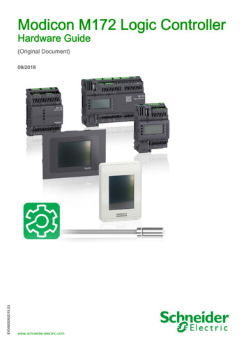
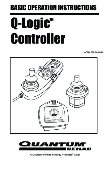
About the Modicon M221 Logic ControllerDelivery ContentThe following figure shows the content of the delivery for a TM221C Logic Controller:1234TM221C Logic Controller Instruction SheetTM221C Logic ControllerBattery holder with lithium carbon monofluoride battery, type Panasonic BR2032.Analog cableEIO0000001360 04/201419
About the Modicon M221 Logic ControllerTM221M Logic Controller DescriptionOverviewThe TM221M Logic Controller has various powerful features and can service a wide range ofapplications.Hardware configuration, programming, and commissioning are accomplished with the SoMachineBasic software described in the SoMachine Basic - Operating Guide.Programming LanguagesThe M221 Logic Controller is configured and programmed with the SoMachine Basic software,which supports the following IEC 61131-3 programming languages:z IL: Instruction Listz LD: Ladder Diagramz Grafcet (List)Power SupplyThe power supply of the TM221M Logic Controller is 24 Vdc (see Modicon M221 Logic Controller,Hardware Guide).Real Time ClockThe M221 Logic Controller includes a Real Time Clock (RTC) system.Run/StopThe M221 Logic Controller can be operated externally by the following:z a hardware Run/Stop switchz a Run/Stop operation by a dedicated digital input, defined in the software configuration (for moreinformation, refer to Configuring Digital Inputs (see page 64))z SoMachine Basic software (for more information, refer to Toolbar (see SoMachine Basic,Operating Guide)).MemoryThis table describes the different types of memory:20Memory TypeSizeUsed toRAM512 Kbyte, of which 256 Kbyte availablefor the application.execute the application and containsdataFlash1.5 Mbyte, of which 256 Kbyte is used tobackup the user application and data incase of power outage.save the applicationEIO0000001360 04/2014
About the Modicon M221 Logic ControllerEmbedded Inputs/OutputsThe following embedded I/O types are available, depending on the controller reference:Regular inputsz Fast inputs (HSC)z Regular transistor outputsz Fast transistor outputs (PWM/PLS)z Relay outputsz Analog inputsz Analog outputszEmbedded Communication FeaturesThe following communication ports are available on the front panel of the controller, depending onthe controller reference:z Ethernetz USB Mini-Bz SD Cardz Serial Line 1z Serial Line 2TM221M Logic ControllersReferenceDigital InputDigital OutputAnalog CommunicationInputPortTM221M16R4 regular inputs(1)4 fast inputs8 relay outputsYesRemovable2 serial line ports1 USB programming screw terminalblocksport8 relay outputsYesRemovable2 serial line ports1 USB programming spring terminalblocksport8 relay outputsYesRemovable1 serial line port1 USB programming screw terminalblocksport1 Ethernet port8 relay outputsYesRemovable1 serial line port1 USB programming spring terminalblocksport1 Ethernet port(HSC)(2)TM221M16RG4 regular inputs(1)4 fast inputs(HSC)(2)TM221ME16R4 regular inputs(1)4 fast inputs(HSC)(2)TM221ME16RG4 regular inputs(1)4 fast inputs(HSC)(2)Terminal Type(1) The regular inputs have a maximum frequency of 5 kHz.(2) The fast inputs can be used either as regular inputs or as fast inputs for counting or event functions.(3) The fast transistor outputs can be used as regular transistor outputs, or for PWM, PLS functions, or reflexoutputs for HSC.EIO0000001360 04/201421
About the Modicon M221 Logic ControllerReferenceDigital InputDigital OutputTM221M16T4 regular inputs(1)4 fast inputs6 regularYestransistoroutputs2 fast transistoroutputs(HSC)(2)Analog CommunicationInputPortTerminal TypeRemovable2 serial line ports1 USB programming screw terminalblocksport(PWM/PLS)(3)TM221M16TG4 regular inputs(1)4 fast inputs(HSC)(2)6 regularYestransistoroutputs2 fast transistoroutputsRemovable2 serial line ports1 USB programming spring terminalblocksport(PWM/PLS)(3)TM221ME16T4 regular inputs(1)4 fast inputs(HSC)(2)6 regularYestransistoroutputs2 fast transistoroutputsRemovable1 serial line port1 USB programming screw terminalblocksport1 Ethernet port(PWM/PLS)(3)TM221ME16TG4 regular inputs(1)4 fast inputs(HSC)(2)6 regularYestransistoroutputs2 fast transistoroutputs1 serial line portUSB programmingport1 Ethernet portRemovablespring terminalblocks(PWM/PLS)(3)TM221M32TK12 regular inputs(1) 14 regulartransistor4 fast inputsoutputs(2)(HSC)2 fast outputsYesHE10 (MIL 20)2 serial line ports1 USB programming connectorsportYesHE10 (MIL 20)1 serial line port1 USB programming connectorsport1 Ethernet port(PWM/PLS)(3)TM221ME32TK12 regular inputs(1) 14 regularoutputs4 fast inputs2 fast outputs(2)(HSC)(PWM/PLS)(3)(1) The regular inputs have a maximum frequency of 5 kHz.(2) The fast inputs can be used either as regular inputs or as fast inputs for counting or event functions.(3) The fast transistor outputs can be used as regular transistor outputs, or for PWM, PLS functions, or reflexoutputs for HSC.22EIO0000001360 04/2014
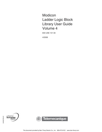
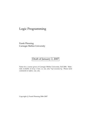
About the Modicon M221 Logic ControllerDelivery ContentThe following figure shows the content of the delivery for a TM221M Logic Controller:1234TM221M Logic Controller Instruction SheetTM221M Logic ControllerBattery holder with lithium carbon monofluoride battery, type Panasonic BR2032.Analog cableEIO0000001360 04/201423
About the Modicon M221 Logic Controller24EIO0000001360 04/2014
Modicon M221Configuration FeaturesEIO0000001360 04/2014Configuration FeaturesChapter 2Configuration FeaturesIntroductionThis chapter provides information related to M221 Logic Controller memory mapping, task, states,behaviors, objects, and functions. The topics explained in this chapter allow the operator tounderstand the featured specifications of M221 Logic Controller that are primarily needed toconfigure and program the controller in SoMachine Basic.What Is in This Chapter?This chapter contains the following sections:SectionTopicPage2.1Objects262.2Task Structure342.3Controller States and Behaviors38EIO0000001360 04/201425
Configuration FeaturesObjectsSection 2.1ObjectsWhat Is in This Section?This section contains the following topics:Topic26PageObjects27Object Types28Addressing I/O Objects30Maximum Number of Objects32EIO0000001360 04/2014
Configuration FeaturesObjectsOverviewIn SoMachine Basic, the term object is used to represent an area of logic controller memoryreserved for use by an application. Objects can be:z Simple software variables, such as memory bits and wordsz Addresses of digital or analog inputs and outputsz Controller-internal variables, such as system words and system bitsz Predefined system functions or function blocks, such as timers and counters.Controller memory is either pre-allocated for certain object types, or automatically allocated whenan application is downloaded to the logic controller.Objects can only be addressed by a program once memory has been allocated. Objects areaddressed using the prefix %. For example, %MW12 is the address of a memory word, %Q0.3 is theaddress of an embedded digital output, and %TM0 is the address of a Timer function block.EIO0000001360 04/201427
Configuration FeaturesObject TypesIntroductionThe language objects for the M221 Logic Controller are classified as follows in the SoMachineBasic software:z Memory objectsz System objectsz I/O objectsz Software objectsThe language object types are described in the following table:Object TypeObjectObject FunctionDescriptionMemoryobjects%MMemory bitsStores memory bit.%MWMemory wordsStores 16 bit memory word.%MDMemory double wordsStores 4 byte memory word.%MFMemory floating pointStores memory floating point in a mathematicalargument which has a decimal in its expression.%KWConstant wordsStores 16 bit constant word.%KDConstant double wordsStores 4 byte constant word.%KFConstant floating pointsStores constant floating point in a mathematicalargument which has a decimal in its expression.%SSystem bits(see page 150)Stores system bit.%SWSystem words(see page 158)Stores system word.%IInput bits (see page 110) Stores value of the digital input.%QOutput bits(see page 111)Stores value of the digital output.%IWInput words(see page 112)Stores value of the analog input.%FCFast counters(see page 116)Serves as either up-counter or down-counter andcounts the rising edge of discrete inputs in single wordor double word computational mode.%HSCHigh speed counters(see page 122)Counts of discrete input in single word or double wordcomputational mode.%PLSPulse generator output(see page 135)Generate square wave signals at dedicated outputchannels and allows only a single signal width, or dutycycle, of 50%.%PWMPulse width modulation(see page 142)Generate square wave signals at dedicated outputchannels and allows variable width and, so, duty cycle.SystemobjectsI/O objects28EIO0000001360 04/2014
Configuration FeaturesObject TypeObjectObject es a time before triggering an action.%CCountersProvides up and down counting of actions.%MSGMessagesStores the status message at the communication port.%RLIFO/FIFO registersStores memory up to 16 words of16 bits each in 2different ways, queue, and stacks.%DRDrum registersOperates on a principle similar to an electromechanicaldrum controller which changes step according toexternal events.%SBRShift bit registersProvides a left or right shift of binary data bits (0 or 1).%SCStep countersProvides a series of steps to which actions can beassigned.SCHSchedule blocksControls actions at a predefined month, day, and time.PIDPID controlProvides a generic control loop feedback in whichoutput is proportional, integral, and derivative of theinput.Memory objects and software objects are generic objects used in SoMachine Basic, whereassystem objects and I/O objects are controller-specific. All controller-specific objects are discussedin the Programming (see page 103) section.For programming details of memory objects and software objects, refer to the SoMachine BasicGeneric Functions Library Guide.EIO0000001360 04/201429
Configuration FeaturesAddressing I/O ObjectsAddressing ExamplesThis table shows addressing examples for various object types:Object TypeSyntaxExampleDescription%Mi%M25Internal memory bit 25.Memory objectsMemory bitsMemory words%MWi%MW15Internal memory word 15.Memory double words%MDi%MD16Internal memory double word 16.Memory floating points%MFi%MF17Internal memory floating point 17.Constant words%KWi%KW26Constant word 26.Constant double words%KDi%KD27Internal constant double word 27.Constant floating points %KFi%KF28Internal constant floating point 28.Sy
About the Modicon M221 Logic Controller 16 EIO0000001360 04/2014 TM221C Logic Controller Description Overview The TM221C Logic Controller has various powerful features and can service a wide range of applications. Software configuration, programming