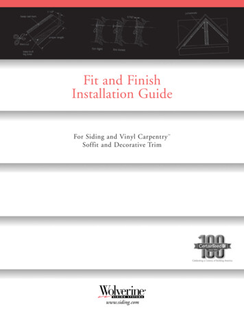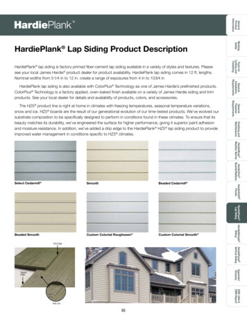
Transcription
Installation Instructions forShakes Siding Panels
Installation Instructionsfor Shake Siding PanelsVytec provides these instructions as installation guidelines. However, Vytec neitherinstalls the siding panels nor has any control over the installation. It is the responsibilityof the contractor and/or the Installer to ensure Vytec siding panels are installed inaccordance with these instructions and any applicable building codes. Vytec assumesno liability for improper installation and/or personal injury and/or property damageresulting from improper use or installation.These installation instructions should not be construed as the only possible way toinstall this siding. Field conditions may dictate different methods. It is the responsibilityof the siding Installer to determine the best methods to use. Reference Building Codesfor additional requirements.1. PRODUCT OVERVIEW.Single 7" Cedar Shakes1.1.1 TRADTITIONAL SHAKE1.1.2 H1.1.4 SC1.1.3 CAPE COD SHAKEPatent Pending1
2. FEATURES2.1 Continuous top and bottom lockVytec siding panels are manufactured with top and bottom continuous locks toinsure the panels are lightly secured to each other.2.2 Engineered nailing hemThe specially engineered nailing hem features right-sized nail slots designed to allowproper expansion and contraction of individual panels to accommodate for naturalfluctuations in temperature.2.3 Temperature markingsTemperature markings are included in each panel to designate the proper gapbetween panels during installation. (See section 4.4 for details)TEMPERATUREMARKINGSNAILING HEM(MARKINGS INDICATECENTER OF NAIL SLOT)CONTINUOUS TOP LOCKCONTINUOUS BOTTOM LOCKPatent Pending2
3. ACCESSORIES REQUIRED FOR PROPER INSTALLATIONStandard siding accessories, with a minimum ¾" pocket width (such as theJ-Channel, inside and outside corner posts, window and door trim) can beused with Vytec siding panels.3.1 Starter stripThe special shake starter strip is recommended for use with Single 7" profile.4. APPLICATION TECHNIQUE4.1 Tools Required Hammer Chalk line Pencil Utility knife Snips (Tin) Tape measure Level Nail slot-punchNOTE: Always use safety goggleswhen using hand or power tools.4.1.1 Methods to cutting panels.For ease of installation, Vytec recommends the use of a circular saw with bladeinstalled so blade is spinning backwards. Siding can be cut with snips or standardutility knife if needed.4.2 Always build wall left to right.All Vytec siding panels are designed to be installed left to right, which is the industrystandard. Right to left installation may be possible in certain circumstances.Installation over various substrates.NOTE: For applications requiring engineering evaluation of wind load parameters,please contact Vytec at:Vytec Corporation803 Belden RoadJackson, MI 49203Attn: Consumer ServicesNail based sheathings.It is recommended to work over a smooth, flat, wall surface.Nails should penetrate a nail based 7/16" minimum.Non-nail based sheathings.For any non-nailable sheathing, Vytec recommends that all nails be driven throughthe sheathing and into the structural framing a minimum of ¾".4.3 Start rows with random lengths.Care should be taken to not use the same length starter panel on the same wall.This wall will minimize the chance of creating a pattern. Cut panels should only beused to start and terminate a course. The minimum panel length should be 16”.Patent Pending3
4.4 Setting the panel gap for temperature.It is important to have the proper amount of gap because the siding panels willexpand and contract with a change in temperature. Each siding panel has temperaturemarkings indicating the proper panel spacing during installation. It is important to setthe panel gap based on panel temperature and not air temperature.Air Temperature Range in FPosition on temperature marking gauge91 F and aboveOn the 100 F line90 F - 76 FBetween 65 F and the 100 F lines75 F – 56 FOn the 65 F line55 F – 41 FBetween 30 F and the 65 F lines40 F and belowOn the 30 F lineSET GAP BY PANEL TEMPERATUREPUSH PANEL UP INTO LOCATION,AS SHOWN4.5 Installing the initial course.4.5.1 Starter stripInstall starter strips at the lowest point of the structure making sure they arelevel. Leave a minimum of ½” gap between the starter strips and any type of trimcomponents (J-channel, inside or outside corner post.).4.5.2 Inside and outside corner postsCorner post and corner trim (J-channel) must be installed before any panels are nailedinto position. Corner posts must extend a minimum of ¾” below the starter strip.Patent Pending4
STARTER STRIPSTARTER STRIP1/2” MIN.STARTER STRIP3/4” MIN.STARTER STRIP3/4” MIN.1/2” MIN.4.5.3 Starting the first courseTo install the first siding panel cut a straight edge on the side that is to be inserted intothe corner trim channel. Hook the bottom lock into the starter strip and slide the panelinto the corner trim channel.the siding panel a minimum of ¼" away from the1/4” KeepMIN. GAPinside edge of the corner trim channel. This allows for expansion of the siding panel.1/4” MIN. GAPCORNER POST CHANNELSTARTER STRIPCORNER POST CHANNELSTARTER STRIPPatent Pending5
Nail the siding panel to the structural member (stud or nail base) closest to the centerof the panel and working out to the ends. Nail spacing cannot exceed 16". All nailslocated in the nailing hem must be driven until there is a 1/16" gap between the nailhead and the siding panel. This allows for expansion and contraction of the sidingpanel. Nails must be located in the center of nailing slots.1/16” GAP3/4” MIN. PENETRATION1/16” GAP3/4” MIN. PENETRATIONSTRUCTURAL MEMBERNAIL IN CENTER OF SLOTSNote: Do not nail tight to wall.STRUCTURAL MEMBERNAIL IN CENTER OF SLOTSVytec siding panels must be nailed at a minimum frequency of 16". A ¾" minimumnail penetration to a structural member (stud or nail base) is required. Install the secondpanel by hooking onto the starter strip and overlapping the male side lock (Temperaturemarkings section 4.4).Position the second panel to the required gap for expansion and nail into location.SETnailingGAPFIRST NAILStart bythe panel NAILin the centerarea and working out.SET GAPNAILFIRST NAILContinue with this process until the first course is completed remembering to leave aminimum ¼" gap for the last panel into the corner trim channel.4.6 Installing the second and subsequent coursesStart each subsequent course with random length siding panels to prevent a repetitivejoint or grain pattern. When applying your first piece make sure the continuous bottomlock is fully engaged with the continuous top lock of the previous course.Patent Pending6
PUSH INTO CONTINUOUSTOP LOCK, AS SHOWNPUSH INTO CONTINUOUSTOP LOCK, AS SHOWNSECOND COURSEMake sure a minimum of 6" of the continuous top lock is remaining exposed for thenext panel to lock onto.6” MINIMUMSECOND COURSECONTINUOUS TOP LOCKFIRST COURSE6” MINIMUMSTARTER STRIPCONTINUOUS TOP LOCKFIRST COURSESTARTER STRIPPosition the next panel for the required gap for expansion and nail into place.4.7 Mansard RoofsWith a 45/12 slope or greater are acceptable applications when installed over aweather barrier rated for the application.Patent Pending7
5. TRIMMING5.1 Installing final courseUse J-channel or Cornice receiver and Cornice molding to finish the final course.Measure from the inside of the trim channel down to the bottom edge of thecontinuous top lock minus ¼". This is the height dimension for the final course.1/4” GAP FOREXPANSION1/4” GAP FOREXPANSIONX DIM1/4” GAP FOREXPANSIONX DIMXDBOTTOM EDGE OFCONTINUOUS TOP LOCKBOTTOM EDGE OFCONTINUOUS TOP LOCKLay the panel face down and measure from the bottom lock up. Cut the panel to thedesired height.SCRIBE LINE,THEN CUTDISCARD THIS SECTIONDISCARD THIS SECTIONSCRIBE LINE,THEN CUTDISCARD THIS SECTIONMEASURE FROMTHIS SURFACEMEASURE FROMTHIS SURFACEX - 1/4”- 1/4”X - 1/4”PUSH INTO J-CHANNELPUSH INTO J-CHANNELPUSH INTO J-CHANIf using a 2-piece channel system, apply channel receiver. Create nail slots every 16" tocut panel and fasten to wall. Snap on J-channel face piece.Patent Pending8
5. TRIMMING - continued5.2 Trimming around openingsMeasure and cut panels for around openings allowing ¼" for expansion. Follow thesame instructions as in section 5.1 for measuring and installing around openings.5.3 Trimming gablesIt is recommended that a template be made for a guide when fitting and cutting panelsfor gables. Any scrap wood or material at least 12" wide can be utilized to make theguide. Snap into location any scrap of panel into the gable starter course. With the12" wide scrap material placed against the bottom of the gable, scribe a line ontothe scrap panel.HOLD AGAINSTGABLESCRIBE LINE.CUT ALONG LINETO CREATE TEMPLATEDISCARD THISSECTION12” MIN.GABLE STARTER COURSECut along the line and now you have a gable template. Use the template to cutall gable mating panels remembering to maintain a ¼" gap for expansion insideall trim channels.5.4 Trimming fixturesFixtures cannot be attached directly to the siding. Always use a block or a J-box toattach fixtures. Drill a hole slightly larger than the diameter of the fasteners, allowingfor expansion and contraction. Note that fasteners must penetrate the solid substrate.Patent Pending9
6. TIPSCare should be taken to not use the same length starter panel on the same wall. Thiswill minimize the chance of creating a pattern. Cut panels should only be used to startand terminate a course. The minimum panel length should be 16".Always start at the lowest point of the structure.Nailing the panels should not restrict movement. Nails should be driven straight intothe center of any nailing slots leaving about 1/16" between the nail head and the panel.Allow ¼" clearance in receiving channels.To ensure panels are hanging straight and level, every 5-6 course stretch a chalk lineacross the wall and use as a guide.Always store siding panels flat. Never bend siding panels.Read installation instructions thoroughly.Patent Pending10
Pub. No. 60066. 3/12 Vytec.For additional information visit our Web site at www.vytec.com or call 1-800-265-2230.
Vytec provides these instructions as installation guidelines. However, Vytec neither installs the siding panels nor has any control over the installation. It is the responsibility of the contractor and/or the Installer to ensure Vytec siding panels are installed in accordance with these instructions and any applicable building codes. Vytec assumes