Transcription
Modicon M241 Logic ControllerEIO0000001432 12/2015Modicon M241 LogicControllerProgramming .com
The information provided in this documentation contains general descriptions and/or technicalcharacteristics of the performance of the products contained herein. This documentation is notintended as a substitute for and is not to be used for determining suitability or reliability of theseproducts for specific user applications. It is the duty of any such user or integrator to perform theappropriate and complete risk analysis, evaluation and testing of the products with respect to therelevant specific application or use thereof. Neither Schneider Electric nor any of its affiliates orsubsidiaries shall be responsible or liable for misuse of the information contained herein. If youhave any suggestions for improvements or amendments or have found errors in this publication,please notify us.No part of this document may be reproduced in any form or by any means, electronic ormechanical, including photocopying, without express written permission of Schneider Electric.All pertinent state, regional, and local safety regulations must be observed when installing andusing this product. For reasons of safety and to help ensure compliance with documented systemdata, only the manufacturer should perform repairs to components.When devices are used for applications with technical safety requirements, the relevantinstructions must be followed.Failure to use Schneider Electric software or approved software with our hardware products mayresult in injury, harm, or improper operating results.Failure to observe this information can result in injury or equipment damage. 2015 Schneider Electric. All rights reserved.2EIO0000001432 12/2015
Table of ContentsSafety Information . . . . . . . . . . . . . . . . . . . . . . . . . . . . .About the Book. . . . . . . . . . . . . . . . . . . . . . . . . . . . . . . .Chapter 1 About the Modicon M241 Logic Controller . . . . . . . . .M241 Logic Controller Description . . . . . . . . . . . . . . . . . . . . . . . . . . .Chapter 2 How to Configure the Controller . . . . . . . . . . . . . . . . . .How to Configure the Controller . . . . . . . . . . . . . . . . . . . . . . . . . . . . .Chapter 3 Libraries . . . . . . . . . . . . . . . . . . . . . . . . . . . . . . . . . . . . .Libraries . . . . . . . . . . . . . . . . . . . . . . . . . . . . . . . . . . . . . . . . . . . . . . . .Chapter 4 Supported Standard Data Types. . . . . . . . . . . . . . . . . .Supported Standard Data Types . . . . . . . . . . . . . . . . . . . . . . . . . . . . .Chapter 5 Memory Mapping . . . . . . . . . . . . . . . . . . . . . . . . . . . . . .Controller Memory Organization . . . . . . . . . . . . . . . . . . . . . . . . . . . . .RAM Memory Organization . . . . . . . . . . . . . . . . . . . . . . . . . . . . . . . . .Flash Memory Organization . . . . . . . . . . . . . . . . . . . . . . . . . . . . . . . .Relocation Table . . . . . . . . . . . . . . . . . . . . . . . . . . . . . . . . . . . . . . . . .Chapter 6 Tasks . . . . . . . . . . . . . . . . . . . . . . . . . . . . . . . . . . . . . . . .Maximum Number of Tasks. . . . . . . . . . . . . . . . . . . . . . . . . . . . . . . . .Task Configuration Screen . . . . . . . . . . . . . . . . . . . . . . . . . . . . . . . . .Task Types . . . . . . . . . . . . . . . . . . . . . . . . . . . . . . . . . . . . . . . . . . . . .System and Task Watchdogs . . . . . . . . . . . . . . . . . . . . . . . . . . . . . . .Task Priorities . . . . . . . . . . . . . . . . . . . . . . . . . . . . . . . . . . . . . . . . . . .Default Task Configuration . . . . . . . . . . . . . . . . . . . . . . . . . . . . . . . . .Chapter 7 Controller States and Behaviors. . . . . . . . . . . . . . . . . .7.1 Controller State Diagram . . . . . . . . . . . . . . . . . . . . . . . . . . . . . . . . . . .Controller State Diagram . . . . . . . . . . . . . . . . . . . . . . . . . . . . . . . . . . .7.2 Controller States Description. . . . . . . . . . . . . . . . . . . . . . . . . . . . . . . .Controller States Description. . . . . . . . . . . . . . . . . . . . . . . . . . . . . . . .7.3 State Transitions and System Events . . . . . . . . . . . . . . . . . . . . . . . . .Controller States and Output Behavior . . . . . . . . . . . . . . . . . . . . . . . .Commanding State Transitions . . . . . . . . . . . . . . . . . . . . . . . . . . . . . .Error Detection, Types, and Management. . . . . . . . . . . . . . . . . . . . . .Remanent Variables . . . . . . . . . . . . . . . . . . . . . . . . . . . . . . . . . . . . . .EIO0000001432 15253575761626571723
Chapter 8 Controller Device Editor . . . . . . . . . . . . . . . . . . . . . . . .Controller Parameters . . . . . . . . . . . . . . . . . . . . . . . . . . . . . . . . . . . . .Controller Selection . . . . . . . . . . . . . . . . . . . . . . . . . . . . . . . . . . . . . . .PLC Settings . . . . . . . . . . . . . . . . . . . . . . . . . . . . . . . . . . . . . . . . . . . .Services . . . . . . . . . . . . . . . . . . . . . . . . . . . . . . . . . . . . . . . . . . . . . . . .Chapter 9 Embedded Inputs and Outputs Configuration . . . . . .Embedded I/Os Configuration . . . . . . . . . . . . . . . . . . . . . . . . . . . . . . .Chapter 10 Expert Functions Configuration . . . . . . . . . . . . . . . . . .Expert Functions Overview . . . . . . . . . . . . . . . . . . . . . . . . . . . . . . . . .Counting Function . . . . . . . . . . . . . . . . . . . . . . . . . . . . . . . . . . . . . . . .Pulse Generators Embedded Function . . . . . . . . . . . . . . . . . . . . . . . .Chapter 11 Cartridge Configuration. . . . . . . . . . . . . . . . . . . . . . . . .TMC4 Cartridge Configuration . . . . . . . . . . . . . . . . . . . . . . . . . . . . . . .Chapter 12 Expansion Modules Configuration . . . . . . . . . . . . . . . .I/O Configuration General Practices . . . . . . . . . . . . . . . . . . . . . . . . . .I/O Bus Configuration. . . . . . . . . . . . . . . . . . . . . . . . . . . . . . . . . . . . . .TM4 Expansion Module Configuration . . . . . . . . . . . . . . . . . . . . . . . . .TM3/TM2 Expansion Module Configuration. . . . . . . . . . . . . . . . . . . . .Optional I/O Expansion Modules . . . . . . . . . . . . . . . . . . . . . . . . . . . . .Chapter 13 Ethernet Configuration . . . . . . . . . . . . . . . . . . . . . . . . .13.1 Ethernet Services. . . . . . . . . . . . . . . . . . . . . . . . . . . . . . . . . . . . . . . . .Presentation . . . . . . . . . . . . . . . . . . . . . . . . . . . . . . . . . . . . . . . . . . . . .IP Address Configuration . . . . . . . . . . . . . . . . . . . . . . . . . . . . . . . . . . .Modbus TCP Client/Server . . . . . . . . . . . . . . . . . . . . . . . . . . . . . . . . .Web Server . . . . . . . . . . . . . . . . . . . . . . . . . . . . . . . . . . . . . . . . . . . . .FTP Server. . . . . . . . . . . . . . . . . . . . . . . . . . . . . . . . . . . . . . . . . . . . . .SNMP. . . . . . . . . . . . . . . . . . . . . . . . . . . . . . . . . . . . . . . . . . . . . . . . . .13.2 Firewall Configuration . . . . . . . . . . . . . . . . . . . . . . . . . . . . . . . . . . . . .Introduction . . . . . . . . . . . . . . . . . . . . . . . . . . . . . . . . . . . . . . . . . . . . .Dynamic Changes Procedure . . . . . . . . . . . . . . . . . . . . . . . . . . . . . . .Firewall Behavior . . . . . . . . . . . . . . . . . . . . . . . . . . . . . . . . . . . . . . . . .Script File Syntax . . . . . . . . . . . . . . . . . . . . . . . . . . . . . . . . . . . . . . . . .13.3 Ethernet Optional Devices . . . . . . . . . . . . . . . . . . . . . . . . . . . . . . . . . .Ethernet Manager . . . . . . . . . . . . . . . . . . . . . . . . . . . . . . . . . . . . . . . .EtherNet/IP Device. . . . . . . . . . . . . . . . . . . . . . . . . . . . . . . . . . . . . . . .Modbus TCP Slave Device . . . . . . . . . . . . . . . . . . . . . . . . . . . . . . . . 000001432 12/2015
Chapter 14 Serial Line Configuration. . . . . . . . . . . . . . . . . . . . . . . .Serial Line Configuration . . . . . . . . . . . . . . . . . . . . . . . . . . . . . . . . . . .SoMachine Network Manager . . . . . . . . . . . . . . . . . . . . . . . . . . . . . . .Modbus Manager. . . . . . . . . . . . . . . . . . . . . . . . . . . . . . . . . . . . . . . . .ASCII Manager . . . . . . . . . . . . . . . . . . . . . . . . . . . . . . . . . . . . . . . . . .Modbus IOScanner . . . . . . . . . . . . . . . . . . . . . . . . . . . . . . . . . . . . . . .Adding a Device on the Modbus IOScanner . . . . . . . . . . . . . . . . . . . .Adding a Modem to a Manager . . . . . . . . . . . . . . . . . . . . . . . . . . . . . .Chapter 15 CANopen Configuration. . . . . . . . . . . . . . . . . . . . . . . . .CANopen Interface Configuration . . . . . . . . . . . . . . . . . . . . . . . . . . . .Chapter 16 Post Configuration . . . . . . . . . . . . . . . . . . . . . . . . . . . . .Post Configuration Presentation . . . . . . . . . . . . . . . . . . . . . . . . . . . . .Post Configuration File Management . . . . . . . . . . . . . . . . . . . . . . . . .Post Configuration Example . . . . . . . . . . . . . . . . . . . . . . . . . . . . . . . .Chapter 17 Connecting a Modicon M241 Logic Controller to a PCConnecting the Controller to a PC . . . . . . . . . . . . . . . . . . . . . . . . . . . .Chapter 18 SD Card . . . . . . . . . . . . . . . . . . . . . . . . . . . . . . . . . . . . . .Updating Modicon M241 Logic Controller Firmware . . . . . . . . . . . . . .File Transfer with SD Card . . . . . . . . . . . . . . . . . . . . . . . . . . . . . . . . .Appendices.Appendix A Functions to Get/Set Serial Line Configuration in UserProgram. . . . . . . . . . . . . . . . . . . . . . . . . . . . . . . . . . . . . .GetSerialConf: Get the Serial Line Configuration . . . . . . . . . . . . . . . .SetSerialConf: Change the Serial Line Configuration . . . . . . . . . . . . .SERIAL CONF: Structure of the Serial Line Configuration Data TypeAppendix B Controller Performance . . . . . . . . . . . . . . . . . . . . . . . . .Processing Performance . . . . . . . . . . . . . . . . . . . . . . . . . . . . . . . . . . .GlossaryIndexEIO0000001432 2052052092102132192212222232252272272292395
6EIO0000001432 12/2015
Safety InformationImportant InformationNOTICERead these instructions carefully, and look at the equipment to become familiar with the devicebefore trying to install, operate, service, or maintain it. The following special messages may appearthroughout this documentation or on the equipment to warn of potential hazards or to call attentionto information that clarifies or simplifies a procedure.EIO0000001432 12/20157
PLEASE NOTEElectrical equipment should be installed, operated, serviced, and maintained only by qualifiedpersonnel. No responsibility is assumed by Schneider Electric for any consequences arising out ofthe use of this material.A qualified person is one who has skills and knowledge related to the construction and operationof electrical equipment and its installation, and has received safety training to recognize and avoidthe hazards involved.8EIO0000001432 12/2015
About the BookAt a GlanceDocument ScopeThe purpose of this document is to help you to program and operate your Modicon M241 LogicController with the SoMachine software.NOTE: Read and understand this document and all related documents before installing, operating,or maintaining your Modicon M241 Logic Controller.The Modicon M241 Logic Controller users should read through the entire document to understandall features.Validity NoteThis document has been updated for the release of SoMachine V4.1 SP2.Related DocumentsTitle of DocumentationReference NumberSoMachine Programming GuideEIO0000000067 (ENG);EIO0000000069 (FRE);EIO0000000068 (GER);EIO0000000071 (SPA);EIO0000000070 (ITA);EIO0000000072 (CHS)Modicon M241 Logic Controller Hardware GuideEIO0000001456 (ENG);EIO0000001457 (FRE);EIO0000001458 (GER);EIO0000001459 (SPA);EIO0000001460 (ITA);EIO0000001461 (CHS)Modicon TM2 Expansion Modules Configuration Programming GuideEIO0000000396 (ENG);EIO0000000397 (FRE);EIO0000000398 (GER);EIO0000000399 (SPA);EIO0000000400 (ITA);EIO0000000401 (CHS)EIO0000001432 12/20159
10Title of DocumentationReference NumberModicon TM3 Expansion Modules Configuration Programming GuideEIO0000001402 (ENG);EIO0000001403 (FRE);EIO0000001404 (GER);EIO0000001405 (SPA);EIO0000001406 (ITA);EIO0000001407 (CHS)Modicon TM4 Expansion Modules Programming GuideEIO0000001802 (ENG);EIO0000001803 (FRE);EIO0000001804 (GER);EIO0000001805 (SPA);EIO0000001806 (ITA);EIO0000001807 (CHS)Modicon TMC4 Cartridges Programming GuideEIO0000001790 (ENG);EIO0000001791 (FRE);EIO0000001792 (GER);EIO0000001793 (SPA);EIO0000001794 (ITA);EIO0000001795 (CHS)Modicon M241 Logic Controller PLCSystem Library GuideEIO0000001438 (ENG);EIO0000001439 (FRE);EIO0000001440 (GER);EIO0000001441 (SPA);EIO0000001442 (ITA);EIO0000001443 (CHS)Modicon M241 Logic Controller HSC Library GuideEIO0000001444 (ENG);EIO0000001445 (FRE);EIO0000001446 (GER);EIO0000001447 (SPA);EIO0000001448 (ITA);EIO0000001449 (CHS)Modicon M241 Logic Controller PTO/PWM Library GuideEIO0000001450 (ENG);EIO0000001451 (FRE);EIO0000001452 (GER);EIO0000001453 (SPA);EIO0000001454 (ITA);EIO0000001455 (CHS)EIO0000001432 12/2015
Title of DocumentationReference NumberSoMachine Controller Assistant User GuideEIO0000001671 (ENG);EIO0000001672 (FRE);EIO0000001673 (GER);EIO0000001675 (SPA);EIO0000001674 (ITA);EIO0000001676 (CHS)You can download these technical publications and other technical information from our websiteat http://download.schneider-electric.comProduct Related InformationWARNINGLOSS OF CONTROL The designer of any control scheme must consider the potential failure modes of control pathsand, for certain critical control functions, provide a means to achieve a safe state during andafter a path failure. Examples of critical control functions are emergency stop and overtravelstop, power outage and restart.Separate or redundant control paths must be provided for critical control functions.System control paths may include communication links. Consideration must be given to theimplications of unanticipated transmission delays or failures of the link.Observe all accident prevention regulations and local safety guidelines.1Each implementation of this equipment must be individually and thoroughly tested for properoperation before being placed into service.Failure to follow these instructions can result in death, serious injury, or equipmentdamage.1For additional information, refer to NEMA ICS 1.1 (latest edition), "Safety Guidelines for theApplication, Installation, and Maintenance of Solid State Control" and to NEMA ICS 7.1 (latestedition), "Safety Standards for Construction and Guide for Selection, Installation and Operation ofAdjustable-Speed Drive Systems" or their equivalent governing your particular location.WARNINGUNINTENDED EQUIPMENT OPERATION Only use software approved by Schneider Electric for use with this equipment.Update your application program every time you change the physical hardware configuration.Failure to follow these instructions can result in death, serious injury, or equipmentdamage.EIO0000001432 12/201511
Terminology Derived from StandardsThe technical terms, terminology, symbols and the corresponding descriptions in this manual, orthat appear in or on the products themselves, are generally derived from the terms or definitionsof international standards.In the area of functional safety systems, drives and general automation, this may include, but is notlimited to, terms such as safety, safety function, safe state, fault, fault reset, malfunction, failure,error, error message, dangerous, etc.Among others, these standards include:12StandardDescriptionEN 61131-2:2007Programmable controllers, part 2: Equipment requirements and tests.ISO 13849-1:2008Safety of machinery: Safety related parts of control systems.General principles for design.EN 61496-1:2013Safety of machinery: Electro-sensitive protective equipment.Part 1: General requirements and tests.ISO 12100:2010Safety of machinery - General principles for design - Risk assessment and riskreductionEN 60204-1:2006Safety of machinery - Electrical equipment of machines - Part 1: GeneralrequirementsEN 1088:2008ISO 14119:2013Safety of machinery - Interlocking devices associated with guards - Principles fordesign and selectionISO 13850:2006Safety of machinery - Emergency stop - Principles for designEN/IEC 62061:2005Safety of machinery - Functional safety of safety-related electrical, electronic, andelectronic programmable control systemsIEC 61508-1:2010Functional safety of electrical/electronic/programmable electronic safety-relatedsystems: General requirements.IEC 61508-2:2010Functional safety of electrical/electronic/programmable electronic safety-relatedsystems: Requirements for electrical/electronic/programmable electronic safetyrelated systems.IEC 61508-3:2010Functional safety of electrical/electronic/programmable electronic safety-relatedsystems: Software requirements.IEC 61784-3:2008Digital data communication for measurement and control: Functional safety fieldbuses.2006/42/ECMachinery Directive2004/108/ECElectromagnetic Compatibility Directive2006/95/ECLow Voltage DirectiveEIO0000001432 12/2015
In addition, terms used in the present document may tangentially be used as they are derived fromother standards such as:StandardDescriptionIEC 60034 seriesRotating electrical machinesIEC 61800 seriesAdjustable speed electrical power drive systemsIEC 61158 seriesDigital data communications for measurement and control – Fieldbus for use inindustrial control systemsFinally, the term zone of operation may be used in conjunction with the description of specifichazards, and is defined as it is for a hazard zone or danger zone in the EC Machinery Directive(EC/2006/42) and ISO 12100:2010.NOTE: The aforementioned standards may or may not apply to the specific products cited in thepresent documentation. For more information concerning the individual standards applicable to theproducts described herein, see the characteristics tables for those product references.EIO0000001432 12/201513
14EIO0000001432 12/2015
Modicon M241 Logic ControllerAbout the Modicon M241 Logic ControllerEIO0000001432 12/2015Chapter 1About the Modicon M241 Logic ControllerAbout the Modicon M241 Logic ControllerM241 Logic Controller DescriptionOverviewThe M241 Logic Controller has various powerful features and can service a wide range ofapplications.Software configuration, programming, and commissioning is accomplished with the SoMachinesoftware described in the SoMachine Programming Guide and the M241 Logic ControllerProgramming Guide.Programming LanguagesThe M241 Logic Controller is configured and programmed with the SoMachine software, whichsupports the following IEC 61131-3 programming languages: IL: Instruction List ST: Structured Text FBD: Function Block Diagram SFC: Sequential Function Chart LD: Ladder DiagramSoMachine software can also be used to program these controllers using CFC (ContinuousFunction Chart) language.Power SupplyThe power supply of the M241 Logic Controller is 24 Vdc or 100.240 Vac.Real Time ClockThe M241 Logic Controller includes a Real Time Clock (RTC) system.Run/StopThe M241 Logic Controller can be operated externally by the following:a hardware Run/Stop switch a Run/Stop operation by a dedicated digital input, defined in the software configuration. Formore information, refer to Configuration of Digital Inputs (see page 84). a SoMachine software command EIO0000001432 12/201515
About the Modicon M241 Logic ControllerMemoryThis table describes the different types of memory:Memory TypeSizeUsed toRAM64 Mbytes, of which 8 Mbytes execute the application.available for the applicationNon-volatile128 Mbytessave the program and data in case of a power interruption.Embedded Inputs/OutputsThe following embedded I/O types are available, depending on the controller reference:Regular inputs Fast inputs associated with counters Regular sink/source transistor outputs Fast sink/source transistor outputs associated with pulse generators Relay outputs Removable StorageThe M241 Logic Controllers include an embedded SD card slot.The main uses of the SD card are: Initializing the controller with a new application Updating the controller firmware Applying post configuration files to the controller Applying recipes Receiving data logging filesEmbedded Communication FeaturesThe following types of communication ports are available depending on the controller reference: CANopen Master Ethernet USB Mini-B Serial Line 1 Serial Line 216EIO0000001432 12/2015
About the Modicon M241 Logic ControllerM241 Logic ControllerReferenceDigital InputsDigital OutputsCommunicationPortsTerminal TypePowersupplyTM241C24R6 regular inputs(1)8 fast inputs6 2A relay outputs4 source fast outputs2 serial line ports1 USB programmingportRemovablescrew terminalblocks100.240 Vac2 serial line ports1 USB programmingport1 Ethernet portRemovablescrew terminalblocks100.240 Vac2 serial line ports1 Ethernet port1 CANopen masterport1 USB programmingportRemovablescrew terminalblocks100.240 Vac2 serial line ports1 USB programmingportRemovablescrew terminalblocks24 Vdc2 serial line ports1 USB programmingport1 Ethernet portRemovablescrew terminalblocks24 Vdc2 serial line ports1 USB programmingport1 Ethernet port1 CANopen masterportRemovablescrew terminalblocks24 Vdc2 serial line ports1 USB programmingportRemovablescrew terminalblocks24 VdcTM241CE24R(counters)(2)(pulse generators)(3)6 regular inputs(1)8 fast inputs6 2A relay outputs4 source fast outputs(counters)(2)TM241CEC24R 6 regular inputs(1)8 fast inputsTM241C24T(pulse generators)(3)6 2A relay outputs4 source fast outputs(counters)(2)(pulse generators)(3)6 regular inputs(1)8 fast inputsSource outputs6 regular transistoroutputs4 fast outputs (pulse(counters)(2)generators)(3)TM241CE24T6 regular inputs(1)8 fast inputs(counters)(2)Source outputs6 regular transistoroutputs4 fast outputs (pulsegenerators)(3)TM241CEC24T 6 regular inputs(1)8 fast inputs(counters)(2)Source outputs6 regular transistoroutputs4 fast outputs (pulsegenerators)(3)TM241C24U6 regular inputs(1)8 fast inputs(counters)(2)Sink outputs6 regular transistoroutputs4 fast outputs (pulsegenerators)(3)(1) The regular inputs have a maximum frequency of 5 kHz.(2) The fast inputs can be used either as regular inputs or as fast inputs for counting or event functions.(3) The fast transistor outputs can be used either as regular transistor outputs, as reflex outputs for counting function(HSC), or as fast transistor outputs for pulse generator functions (FG / PTO / PWM).EIO0000001432 12/201517
About the Modicon M241 Logic ControllerReferenceDigital InputsDigital OutputsCommunicationPortsTerminal TypePowersupplyTM241CE24U6 regular inputs(1)8 fast inputsSink outputs6 regular transistoroutputs4 fast outputs (pulse2 serial line ports1 USB programmingport1 Ethernet portRemovablescrew terminalblocks24 Vdc2 serial line ports1 USB programmingport1 Ethernet port1 CANopen masterportRemovablescrew terminalblocks24 Vdc2 serial line ports1 USB programmingportRemovablescrew terminalblocks100.240 Vac2 serial line ports1 USB programmingport1 Ethernet portRemovablescrew terminalblocks100.240 Vac2 serial line ports1 USB programmingportRemovablescrew terminalblocks24 Vdc2 serial line ports1 USB programmingport1 Ethernet portRemovablescrew terminalblocks24 Vdc2 serial line ports1 USB programmingportRemovablescrew terminalblocks24 Vdc(counters)(2)generators)(3)TM241CEC24U 6 regular inputs(1)8 fast inputs(counters)(2)Sink outputs6 regular transistoroutputs4 fast outputs (pulsegenerators)(3)TM241C40R16 regularinputs(1)8 fast inputs(counters)TM241CE40R12 2A relay outputs4 source fast outputs(pulse generators)(3)(2)16 regularinputs(1)8 fast inputs12 2A relay outputs4 source fast outputs(pulse generators)(3)(counters)(2)TM241C40T16 regularinputs(1)8 fast inputs(counters)(2)TM241CE40T16 regularinputs(1)8 fast inputs(counters)(2)TM241C40U16 regularinputs(1)8 fast inputs(counters)(2)Source outputs12 regular transistoroutputs4 fast outputs (pulsegenerators)(3)Source outputs12 regular transistoroutputs4 fast outputs (pulsegenerators)(3)Sink outputs12 regular transistoroutputs4 fast outputs (pulsegenerators)(3)(1) The regular inputs have a maximum frequency of 5 kHz.(2) The fast inputs can be used either as regular inputs or as fast inputs for counting or event functions.(3) The fast transistor outputs can be used either as regular transistor outputs, as reflex outputs for counting function(HSC), or as fast transistor outputs for pulse generator functions (FG / PTO / PWM).18EIO0000001432 12/2015
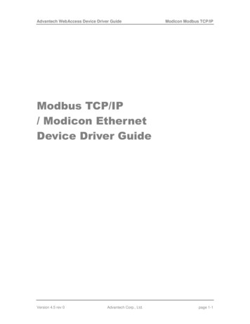
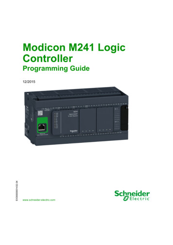
About the Modicon M241 Logic ControllerReferenceDigital InputsDigital OutputsCommunicationPortsTerminal TypePowersupplyTM241CE40U16 regularSink outputs12 regular transistoroutputs4 fast outputs (pulse2 serial line ports1 USB programmingport1 Ethernet portRemovablescrew terminalblocks24 Vdcinputs(1)8 fast inputs(counters)(2)generators)(3)(1) The regular inputs have a maximum frequency of 5 kHz.(2) The fast inputs can be used either as regular inputs or as fast inputs for counting or event functions.(3) The fast transistor outputs can be used either as regular transistor outputs, as reflex outputs for counting function(HSC), or as fast transistor outputs for pulse generator functions (FG / PTO / PWM).Delivery ContentThe following figure presents the content of the delivery for a M241 Logic Controller:123M241 Logic Controller Instruction SheetM241 Logic ControllerLithium carbon monofluoride battery, type Panasonic BR2032.EIO0000001432 12/201519
About the Modicon M241 Logic Controller20EIO0000001432 12/2015
Modicon M241 Logic ControllerHow to Configure the ControllerEIO0000001432 12/2015Chapter 2How to Configure the ControllerHow to Configure the ControllerHow to Configure the ControllerIntroductionFirst, create a new project or open an existing project in the SoMachine software.Refer to the SoMachine Programming Guide for information on how to:add a controller to your project add expansion modules to your controller replace an existing controller convert a controller to a different but compatible device Devices TreeThe Devices tree presents a structured view of the current hardware configuration. When you adda controller to your project, a number of nodes are added to the Devices tree, depending on thefunctions the controller provides.EIO0000001432 12/201521
How to Configure the ControllerItemUse to Configure.DIEmbedded digital inputs of the logic controllerDQEmbedded digital outputs of the logic controllerCountersEmbedded counting functions (HSC)Pulse GeneratorsEmbedded pulse generator functions (PTO/PWM/FG)Cartridge xCartridges plugged into the logic controllerIO BusExpansion modules connected to the logic controllerCOM BusCommunications bus of the logic controllerEthernet xEmbedded Ethernet, serial line, or CANopen communications interfacesSerial Line xNOTE: Ethernet and CANopen are only available on some references.CAN xApplications TreeThe Applications tree allows you to manage project-specific applications as well as globalapplications, POUs, and tasks.Tools TreeThe Tools tree allows you to configure the HMI part of your project and to manage libraries.22EIO0000001432 12/2015
Modicon M241 Logic ControllerLibrariesEIO0000001432 12/2015Chapter 3LibrariesLibrariesLibrariesIntroductionLibraries provide functions, function blocks, data types and global variables that can be used todevelop your project.The Library Manager of SoMachine provides information about the libraries included in yourproject and allows you to install new ones. For more information on the Library Manager, refer tothe Functions and Libraries User Guide.Modicon M241 Logic ControllerWhen you select a Modicon M241 Logic Controller for your application, SoMachine automaticallyloads the following libraries:Library nameDescriptionIoStandardCmpIoMgr configuration types, ConfigAccess, Parameters and helpfunctions: manages the I/Os in the application.StandardContains functions and function blocks which are required matchingIEC61131-3 as standard POUs for an IEC programming system. Linkthe standard POUs to the project (standard.library).UtilAnalog Monitors, BCD Conversions, Bit/Byte Functions, ControllerDatatypes, Function Manipulators, Mathematical Functions, Signals.PLCCommunication(see SoMachine, Modbus andASCII Read/Write Functions,PLCCommunication Library Guide)SysMem, Standard. These functions facilitate communicationsbetween specific devices. Most of them are dedicated to Modbusexchange. Communication functions are processed asynchronouslywith regard to the application task that called the function.M241 PLCSystem (see ModiconM241 Logic Controller, SystemFunctions and Variables,PLCSystem Library Guide)Contains functions and variables to get information and sendcommands to the controller system.M241 HSC (see Modicon M241Logic Controller, High SpeedCounting, HSC Library Guide)Contains function blocks and variables to get information and sendcommands to the Fast Inputs/Outputs of the Modicon M241 LogicController. These function blocks permit you to implement HSC (HighSpeed Counting) functions on the Fast Inputs/Outputs of the ModiconM241 Logic Controller.EIO0000001432 12/201523
Libraries24Library nameDescriptionM241 PTOPWM (see ModiconM241 Logic Controller, PTOPWM,Library Guide)Contains function blocks and varia
The M241 Logic Controller has various powerful features and can service a wide range of applications. Software configuration, programming, and commissioning is accomplished with the SoMachine software described in the SoMachine Programming Guide and the M241 Logic Controller Programming Guide. Programming La