Transcription
Fluidsys Training Centre, Bangalore offers an extensive range ofskill-based and industry-relevant courses in the field ofPneumatics and Hydraulics. For more details, please visit thewebsite: https://fluidsys.org[You may download this article at: https://fluidsys.org/downloads/ ]The Logic of Programmable Logic Controllers (PLCs)A programmable logic controller (PLC) is a modern device that can be used to control the work process in a machine oran appliance. The operations involved in the work process are carried out by some kind of actuators such as electricmotors, pneumatic actuators, hydraulic actuators, etc., which are in turn controlled by final control elements such ascontactors, solenoid valves, etc. Pushbutton switches are generally used for registering the intention of an operator tostart or stop the work operations or to apply an emergency stop. Sensors are used to detect the completion of workoperations and can be used for obtaining the automatic operation of the work process. In the PLC-based controller, theassociated input and output devices are individually connected to the PLC.What is a PLC?1
A PLC is a digital electronic device consisting of hardware and software elements intended for interfacing with the inputdevices such as pushbuttons and sensors and output devices such as motors and solenoid valves in the associatedmachine to achieve the desired control task. It is capable of receiving signals concerning the process variables asprovided by the input devices, processing the signals, and then energizing the final control elements to control theoutput devices, as per the software program or instructions stored in its memory.Hardware Elements of a PLCThe hardware part of the PLC consists essentially of a CPU, a program memory, and input/output (I/O) modules. Apartfrom the PLC along with its hardware elements, the associated PLC system may consist of a PC, a power supply module,a networking module, and a Human-Machine Interface (HMI).The main function of the CPU is to make logical decisions and execute user programs. The memory loads the programsand stores data at addressed locations. The input modules are required to process digital and analog signals so that theyare appropriate for the electronic processing circuits of the CPU. That is, they convert the input signals at the standardindustrial control voltage of 24 V DC, or voltages in the range of 0 to 10 V, or currents in the range of 4 to 20 mA, or atany other levels to signals at the standard CPU voltage of 5V DC (maximum). The output modules are required toconvert the output signals at the standard CPU voltage of 5V DC (maximum) to signals at the external signal levels. Thepower source is required to provide the power to the logic circuits of the processor and the internal power needs of theI/O modules.Hardware Design of PLCsAccording to the arrangement of the I/O modules, the design approach for configuring the PLC system can be of thefixed-I/O design or the modular design. In the fixed-I/O design, the CPU, inputs, and outputs are organized as a singleunit without any scope for further modification. Further, the fixed-I/O PLC has a limited number of inputs and outputs. APLC system can also be set up in a modular fashion by arranging the required modules on a rack as per the systemrequirements of the application.2
Software Elements of a PLCThe software part of a PLC is the overall software used to control not only an external system or process but also thehardware parts of the PLC. Accordingly, it consists of firmware and user programs. The firmware of the PLC is that partof the software that is supplied by the PLC manufacturer and mainly includes the PLC operating system and at least onestandard programming language. The operating system is the overall software representing all the instructions anddeclarations necessary for controlling the PLC system resources. Every programming language includes a comprehensiveset of instructions. The user program can be written by using these instructions for controlling a machine or process.Highly complex programs can be written easily by using a graphical programming language.Program Scan-cycleWhile processing a program in the PLC system, its CPU scans the system inputs, executes the program, and updates thesystem outputs, cyclically. The time that is taken by the PLC in scanning one cycle is called ‘scan cycle time’.Ladder ProgrammingA ladder diagram (one of the PLC programming languages) uses graphic representations of programming instructions,such as contacts and coils for obtaining the required control function. The left-hand side vertical line of the ladderdiagram is considered to be associated with a positive voltage, and the right-hand side vertical line is associated with the0 volt. Between these two lines, there exist a number of horizontal rungs through which a hypothetical current (orpower) is assumed to flow. Initially, the program control elements are inserted to the rungs so as to realize the requiredcontrol logic, and then a program output coil is placed as the terminator of the rung. The ladder programming languageallows PLCs to perform different types of tasks, including bit logic, timing, and counting functions.Bit logic Operations in PLCsThe bit logic (Boolean) operations are provided in the PLC programming language for the bit-wise control of operations.Some important programming instructions for carrying out the bit logic operations are the ‘NO contact’, ‘NC contact’,‘coil’, ‘set coil’, and ‘reset coil’. Each of these elements can be brought to the selected part of a ladder rung by clickingthe program element from the electronic program element catalogue provided in the PLC software.[Please note: In this article, a hypothetical addressing format is used just for explaining the concepts. The exactaddressing format depends on the type and make of the PLC.]NO Contact, PLCThe NO contact has an ‘address’ part for specifying the address of the associated input device or the output device orsome other internal programming element, like a timer. The NO contact scans for the signal state ‘1’ (ON) at thespecified bit address. That is, power is assumed to flow through the NO contact if the scanned bit address has the signalstate ‘1’. This contact is used for scanning the ‘high’ signal state of the input device or output device or internalprogramming element.NC Contact, PLCThe NC contact has an ‘address’ part for specifying the address of the associated input device or the output device orsome other internal program element. The NC contact scans for the signal state ‘0’ (OFF) at the specified bit address.That is, power is assumed to flow through the NC contact if the scanned bit address has the signal state ‘0’. This contactis used for scanning the ‘low’ signal state of the input device or output device or internal programming element.3
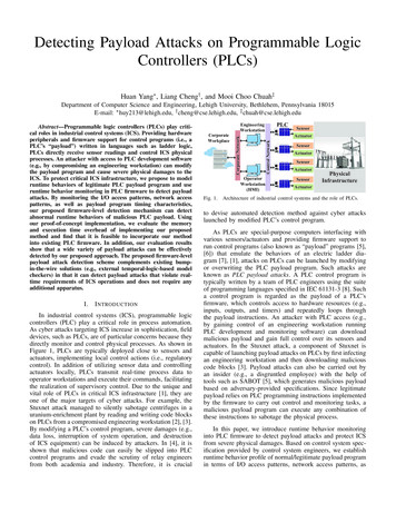
Coil, PLCThe coil has an ‘address’ part for specifying the address of the associated output device. It acts as an interface betweenthe CPU and the output device. That is; when conventional power flows into the coil, the specified bit address is set tothe signal state ‘1’ and energy is delivered to the output device by the PLC.Example 1: Basic ProgrammingA PLC is connected with three NO pushbuttons (PB1, PB2, and PB3) at the input addresses I1, I2, and I3 respectivelyand an NC pushbutton (PB4) at the input address I4, as shown in the wiring diagram. It is also connected with twolamps L1 and L2 at the output addresses O1 and O2. Analyse the given typical ladder programs along with thedescriptions to understand the basic operation of the PLC.Ladder Diagram 1.1 The first NO contact scans for the ‘1’ state of the input at the address I1. This state occurs when theassociated pushbutton PB1 is pressed.The second NO contact scans for the ‘1’ state of the input at the address I3. This state occurs when theassociated pushbutton PB3 is pressed.The output at the address O1 turns to the ‘1’ state and hence the associated output L1 gets energizedwhen the series connected input addresses (I1 and I3) turn to the ‘1’ states simultaneously.Ladder Diagram 1.2 The NO contact scans for the ‘1’ state of the input at the address I4. This state occurs when the associatedpushbutton PB4 remains in the normal position. That is, when the NC pushbutton PB4 is not pressed, theoutput at the address O2 turns to the ‘1’ state as per the ladder diagram, and hence the associated lampL2 gets energized.4
When the pushbutton PB4 is pressed, the state of I4 turns to the ‘0’ state and the state of O2 turns to the‘0’ state, and hence the lamp L2 gets de-energized.Ladder Diagram 1.3 The output address O1 turns to the ‘1’ state, (when the input at the address I1 turns to the ‘1’ state andthe input at the address I2 turns to the ‘0’ state) or (when the input at the address I1 turns to the ‘0’ stateand the address at the input I2 turns to the ‘1’ state). This exclusive OR logic, for the ON condition of thelamp L2, occurs when PB1 is pressed and PB2 is not pressed, or when PB1 is not pressed and PB2 ispressed.Ladder Diagram 1.4 When the input I1 is momentarily set to the ‘1’ state (PB1 is pressed and released), the output O1 is set tothe ‘1’ state (lamp L2 glows). The output O1 remains in the ‘1’ state even if the signal to the input I1 is notpresent. By setting the input I2 to the ‘1’ state momentarily (PB2 is pressed and released), the output O1remains reset (lamp L2 remains in the off state). This program implements the memory function.TimersPLC timer instructions are used for the implementation of time-based operations in various applications. The timespecifications for PLC timers are stored in the addressed locations. The timer instruction basically has a ‘start’ input forrunning the timer and a ‘time value’ input for specifying the required time duration. The desired time duration can bespecified in hours, minutes, seconds, and milliseconds, or an appropriate time base, usually, embedded in a uniqueformat. The status of the timer can be taken from the ‘output’. The timer instruction is also provided with a resettingfeature. A PLC may include many types of timer instructions, such as the on-delay type, off-delay type, retentive ondelay type, pulse type etc.On-delay TimerA hypothetical representation of the on-delay timer with its essential parameters and its behaviour are given in thefigure. The timer has an ‘address’ part for specifying its address location in the memory. The timer starts running when asignal is applied to its ‘Start input’. The signal state of the timer output changes from ‘0’ to ‘1’ when programmed time ‘t’has been elapsed with reference to the change of state of the ‘start’ input from the ‘0’ state to the ‘1’ state (ON). But thesignal state of the timer output changes from the ‘1’ state to the ‘0’ state, as soon as the status of the signal at the startinput changes from the ‘1’ state to the ‘0’ state (OFF), without any time delay.5
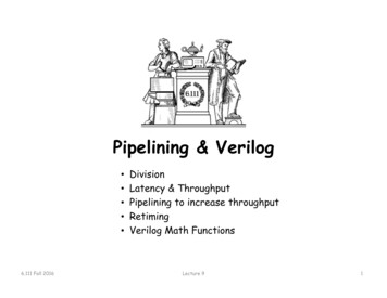
Example 2: Delayed return motion of a hydraulic cylinder using a PLCA double-acting hydraulic cylinder is employed in a pressing machine. A 4/2-DC double solenoid valve acts as the finalcontrol element of the cylinder. When a pushbutton (PB1) is pressed, the cylinder is to extend. The cylinder mustremain in its forward end position for 10 seconds. It should then return to its home position automatically. All theinput and output devices are connected to the PLC. You may analyze the hydraulic circuit, PLC wiring diagram, and theLadder program for getting a better understanding of the PLC-controlled hydraulic system.The hydraulic circuit for the control of the double-acting cylinder consists of the 4/2-way double solenoid valve with coilsY1 and Y2. The PLC wiring diagram shows the connection of the pushbutton (PB1) and the sensor (S2) connected to theinput of the PLC at addresses I1 and I2 respectively and the solenoid coils Y1 and Y2 to the output of the PLC ataddresses O1 and O2 respectively. The ladder diagram to realize the control task is also given. An on-delay timer (ODT)instruction is used to obtain the delayed return motion of the cylinder. Let T1 be the address of the timer. The delaytime of 10s is specified at the time value (TV) input of the timer.When PB1 is pressed momentarily, the signal state of the address I1 changes from ‘0’ to ‘1’ and consequently the signalstate of the output address O1 changes from ‘0’ to ‘1’, as per the program at the rung 1 of the Ladder diagram. The coilY1 is energized causing the forward actuation of the solenoid valve and hence the extension of the cylinder. When thecylinder reaches its forward end position, the limit switch S2 is pressed automatically, and its signal state is turned to ‘1’.The signal from the sensor S2 acts as the start input for the timer (T1). The signal state of the timer changes from ‘0’ to‘1’ when the specified time (10s) has been elapsed, and consequently the signal state of the output address O2 turns to‘1’, as per the program at the rung 2 of the Ladder diagram. The coil Y2 is thus energized causing the return actuation ofthe solenoid valve and the delayed automatic retraction of the cylinder.Memory Elements, PLCA PLC is provided with bit memory locations (flags) for storing intermediate results during a program execution. Each ofthese memory locations can be set or reset by using a set coil or reset coil respectively. A box instruction with thecombined set and reset instructions may also be available in the instruction set of a PLC. Let M1, M2, M3, etc., be thehypothetical addresses of the bit memory locations in the data memory.6
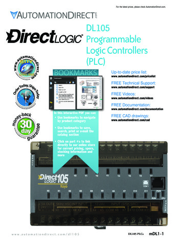
If power flows to the input of the set coil, the signal state of the addressed bit memory location is set to ‘1’. The state ofthe memory address remains the same even if no power goes to the set input subsequently. If the power flows to theinput of the reset coil, the signal state of the addressed memory location is reset to ‘0’. The state of the memory addressremains the same even if no power goes to the reset input subsequently. That means, the coil can remember the lastsignal given. The addressed memory output can be accessed by an NO or NC program instruction.Example 3: Continuous back-and-forth motion of a pneumatic cylinder using a PLCWhen a start pushbutton is pressed, a double-acting pneumatic cylinder is to perform a continuous back-and-forthmotion until a stop pushbutton is pressed. The cyclic operation should always stop with the cylinder in the retractedposition. A 5/2-DC double solenoid valve is used as the final control element, and a PLC is used as the controller. Allthe input and output devices are connected to the PLC. You may analyze the pneumatic circuit, PLC wiring diagram,and the Ladder program for the better understanding of the PLC-controlled pneumatic system.The figure shows the pneumatic circuit for the cyclic operation of the double-acting pneumatic cylinder with the 5/2-waydouble solenoid valve having coils Y1 and Y2. The coil Y1 controls the forward motion of the cylinder, and the coil Y2controls the return motion of the cylinder. Pushbuttons PB1 and PB2 are used to the get the start and stop controlsrespectively. The pushbutton PB1 is connected to the PLC at the address I1, and the pushbutton PB2 is connected to thePLC at the address I2. The limit switch S1 and the proximity sensor S2 are used to get the fully automatic operation ofthe cylinder. These sensors are positioned for actuation at the retracted and extended positions of the cylinder,respectively. The sensor S1 is connected to the PLC at the address I3, and the sensor S2 is connected to the PLC at theaddress I4. The sensor S1 is actuated in the initial position of the cylinder. The coil Y1 is connected to the PLC at theaddress O1, and the coil Y2 is connected to the PLC at the address O2. The figure also shows the PLC wiring diagram. Theladder program to realize the control task is also given.The cyclic operation of the pneumatic cylinder can be obtained just by using the sensor signal S1 (address I3) controllingsolenoid coil Y1 (address O1) through the program as shown in the rung 2 of the Ladder program and the sensor signalS2 (address I4) controlling the solenoid coil Y2 (address O2) through the program as indicated at the rung 3 of theLadder program. The ‘start’ and ‘stop’ controls for the cyclic operation of the cylinder can be realized by introducing amemory element (flag) with the address ‘M1’. The memory location can be set by the momentary actuation of thepushbutton PB1 (address I1) and reset by the momentary actuation of the pushbutton PB2 (address I2), through the7
program as shown at the rung 1 of the ladder program. The signal state of the memory element M1, accessed throughan NO contact, is logically combined in series with the signal state of the sensor S1 (address I3), as shown at the rung 2,to control the coil Y1 (address O1).Example 4: PLC-controlled Automatic Washing MachineA washing machine has to carry out a sequence of operations like washing, rinsing, and drying automatically, when astart pushbutton (PB1) is pressed. The appliance uses a motor for running the agitator of the washing machine, and apump for the water inlet and a pump for draining the water out. A simplified sequence of operations is as follows: theinlet water pump is ON for 30s. Then the agitator motor runs for 20s. Next, the output pump is ON for 25s. You mayanalyze the Timing Diagram and the Ladder program for the better understanding of the PLC-controlled automaticwashing machine.The PLC wiring diagram shows that the ‘start’ pushbutton PB1 is connected to the input of the PLC at the address I1. Thefinal control elements K1, K2, and K3 of the inlet pump, agitator motor, and drain pump are connected to the addressesO1, O2, and O3 respectively.The wash, rinse and drying operations in a washing machine have to be carried out in a timed sequential manner. Thisfact implies that three timers need to be started sequentially to obtain the operations with the necessary timings (Pl. seethe programs at the rungs 2, 3, and 4). The solution for this problem may be obtained in a number of ways. A betterapproach may be to develop a timing diagram for the sequence of operations. It is also possible to shape the pulses withthe use of retentive timers so that the development of the program becomes easy. It may be noted that a retentivetimer needs to be reset once it goes to the ‘1’ state. This timing diagram approach will be beneficial for the advancedautomatic washing machines with complex requirements and crossed-linked logics.A memory flag ‘M’ is set during the entire period of the sequential operations for the convenience of programming (Pl.See the timing diagram and program at the rung 1).8
The programs of the inlet pump, agitator motor, and the drain pump can be written with the help of the timing diagram.As shown in the timing diagram, the control logic for the ON state of the inlet pump, agitator motor, and the drain pumpcan be obtained by associating relevant signals (as marked by the blue lines) at stage 1, stage 2, and stage 3 respectively.These programs are given at the rung 5, 6, and 7.Authored by JOJI Parambath, Founder/Director, Fluidsys Training Centre, BangaloreReference:JOJI PARAMBATH, Industrial Hydraulic Systems – Theory and Practice, Universal Publishers, Boca Raton, USA, method ISBN&book 1627340580Note: A comprehensive account of the topic is given in the textbook on ‘Industrial Hydraulic Systems-Theory and Practice’ by JojiParambath.For more useful article and downloads, please visit:https://fluidsys.org/downloads/Please contact Fluidsys Training Centre, Bangalore for training in the field of Pneumatics, Electro-pneumatics, Hydraulics, Electrohydraulics, etc.email: info@fluidsys.in website: https://fluidsys.org9
Jul 17, 2017 · The Logic of Programmable Logic Controllers (PLCs) A programmable logic controller (PLC) is a modern device that can be used to control the work process in a machine or an appliance. The operations involved in the work process a