Transcription
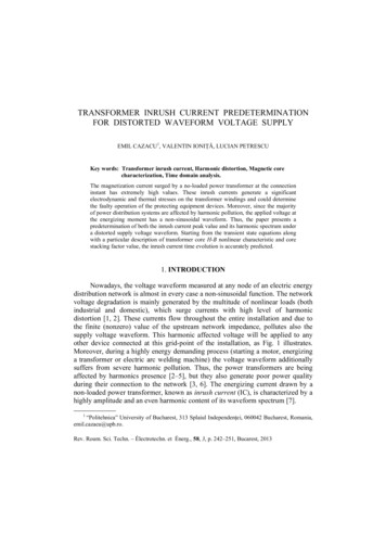
Sympathetic Inrush Current Phenomenon withLoaded TransformersU. Rudez, R. MihalicAbstract-- The magnetization of a transformer is usuallyassociated with the well-known phenomenon of inrush current.However, inrush current does not only affect the transformerbeing switched on. Instead, it has a significant impact also on allparallel connected transformers, which most certainly includesmeasurement transformers. This is known as a sympatheticinrush phenomenon. While the transformer being switched onmight be a subject to a sudden high saturation level, the paralleltransformers are gradually drawn to saturation as well, but ofopposite polarity. The sympathetic inrush is expected in situationswhere the ohmic part represents a significant portion of the totalsystem impedance. In contrast to other available literature on thissubject, in this paper a modal approach to solving equivalentcircuit by expressing differential equations in the state-equationform is selected. From the derivation of eigenvalues andeigenvectors, the phenomenon can be systematically investigated.A special attention will be given to circumstances, when thealready operational transformer is fully loaded as withinsubstations two or more transformers often operate in parallel,among which at least one of them is usually loaded. Finally,simulation results are compared to captured Wide AreaMonitoring System (WAMS) measurements of the phenomenonand reasons for discrepancies are discussed.Keywords: inrush current, magnetization curve, sympatheticinteraction, power system dynamics simulation, WAMSmeasurements.I. INTRODUCTIONTHE transformer inrush phenomenon is very known andwidely described for a long time. If the prospectivemagnetic flux (imaginative steady-state conditions prior toswitching, describing the situation as if the switch was alreadyon) in the transformer iron core at the moment of transformerenergization differs from the value of zero, the flux DCcomponent appears in the transformer core, which decaysexponentially with time. Due to non-linear magnetizingcharacteristic of the transformer iron core (magnetic fluxversus magnetizing current), a DC component of the magneticflux can drive the transformer into saturation, in which thecurrent drawn from the power system no longer changeslinearly with the magnetic flux. Instead, each change inThis work was supported by a Slovenian Research Agency as a part of theresearch program Electric Power Systems, P2-356.The authors are with the Faculty of Electrical Engineering, University ofLjubljana, 1000 Ljubljana, Slovenia (e-mail: si)Paper submitted to the International Conference on Power SystemsTransients (IPST2015) in Cavtat, Croatia June 15-18, 2015magnetic flux generates large currents that contain higherharmonic content. This usually happens during a transformerenergization, especially in case of three-phase transformers, asthe majority of circuit breakers perform a simultaneousswitching of all three phase terminals. The intensity of thephenomenon can be significantly reduced or even omitted bycontrolling the moment of individual phase switching.However, not all transformers are equipped with mechanismsallowing such switching.According to [1] transformer inrush currents might occur indifferent forms and can be divided into the following subcategories: energization inrush (caused by re-application ofvoltage source to the transformer which haspreviously been de-energized. However, remanencecould be still present), sympathetic inrush (caused by re-application ofvoltage source to the transformer, which operates inparallel to two or more other transformers), recovery inrush (caused by restoration of a voltageafter clearance of a fault).The subject of this paper is the second sub-category fromthe above list. Even though the first explanations of thephenomenon can be found in the quite early literature [2], thetopic is also very relevant these days. Authors think it isreasonable to speculate that the need for additional explanationof such important phenomena always exist. This paper is basedon findings and presentations, published in [1], [3], [4], [5],[6], [7], [8] and [9]. Certain additional explanations are addedto papers already published with the strong support from cleargraphical representation. Besides, in contrast to other availableliterature on this subject, in this paper a modal approach tosolving equivalent circuit by expressing differential equationsin the state-equation form is selected. From the derivation ofeigenvalues and eigenvectors, the phenomenon can besystematically investigated.Authors are of opinion that this paper would be veryappreciated among TSOs as well as researches that arebeginning their research on this topic.II. ENERGIZATION INRUSH CURRENTAt first, it is reasonable to briefly explain the basictransformer energization inrush current. The most explanatoryway to do so is by writing a voltage equation based on theKirchhoff's second law for the transformer equivalent circuit,connected via system impedance Zs Rs jωLs to a voltagesource u(t) (Fig. 1). Transformer equivalent circuit is usually
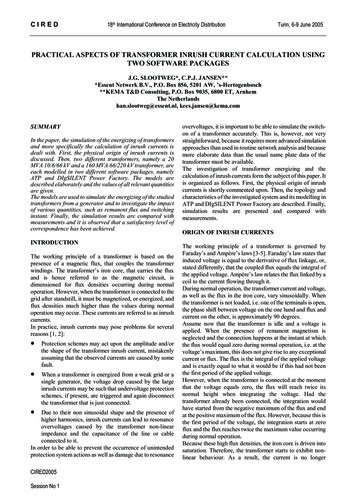
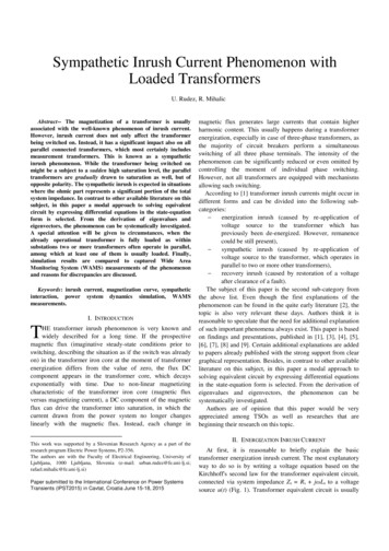
thought of as a “T” circuit, where the denotations represent thefollowing:R1 . resistance of the transformer’s primary winding,Lσ1 . leakage inductance of the transformer’s primarywinding,R2’. resistance of the transformer’s secondary winding(recalculated on the number of primary windingturns N1),Lσ2’ . leakage inductance of the transformer’s secondarywinding (recalculated on the number of primarywinding turns N1),Rm . magnetizing resistance of the transformer,representing iron losses,Lm. magnetizing inductance of the transformer.homogeneous solution of differential equation (2) with aconstant C1 is therefore more or less trivial and equals:Φ DC ( t ) C 1 e R Rs tL Ls(3)By taking into account that the switch from Fig. 1 is turnedon at time t 0 when flux equals ΦDC(0) Φ0 (initialconditions), (3) becomes:Φ DC ( t ) Φ0 e R Rs tL Ls(4)(4) represents the passive circuit response, which isobviously a DC component with a decaying rate determined byratio between circuit serial ohmic resistance and serialinductance. Particular part of the differential equation solutionon the other hand (AC flux component), which is not of mainconcern within this paper, can be obtained by using method ofundetermined coefficient and some trigonometric laws.Assuming the solution in the form of:Φ AC ( t ) C 2 sin (ω t a ) C 3 cos (ω t a )(5)its insertion into (2) gives the unknown constants:C2 L U m ( R Rs )( R Rs )2C3 Fig. 1. Equivalent circuit of a power transformer, connected to a voltagesource via system impedanceAs a transformer inrush current occurs due to the nonlinearity of Lm in the magnetizing branch, the simplest way toanalyze the phenomenon is to assume that the transformer isun-loaded (i2’ 0, consequently the secondary branch isinactive and depicted in grey). This enables writing thefollowing loop voltage equation, where the voltage source u(t) Um · sin(ω·t α) is assumed ideally sinusoidal and the ironlosses are neglected (Rm , also depicted in grey): u ( t ) [ Rs R1 ] i ( t ) d([ Ls Lσ 1 Lm ] i ( t ) ) 0dt(1)where i(t) is(t) i1(t) im(t). For the purpose of simplermathematical derivation, let us assume that Lm is linear (eventhough it is in fact the non-linearity of Lm the ground reasonfor the inrush phenomenon to be so important). Further, let usmerge the transformer quantities and denote R R1 and L Lσ1 Lm. If we assume the relation between current andmagnetic flux L Φ/i, the following expression can beobtained by rewriting (1):R RsLΦ& ( t ) Φ (t ) u (t )L LsL Ls(2)What we are interested in is the passive circuit response, i.e.(2) without voltage source u(t) 0. The so-called ω 2 ( L Ls )2(6)ω L U m ( L Ls )( R Rs )2 ω 2 ( L Ls )2Considering trigonometric equalities:11 β2β1 β2 cos ( arctan ( β ) )(7) sin ( arctan ( β ) )the particular solution equals:Φ AC ( t ) L U m sin ( ω t a Θ )Z(8)where ω ( L Ls ) ( R Rs ) Θ arctan Z ( R Rs )2 ω 2 ( L Ls )(9)2(10)It is clear that the voltage across transformer inductanceUL(t) and its magnetic flux Φ(t) ΦDC(t) ΦAC(t) are π/4shifted, as the definition dictates:U L (t ) N 1 dΦ (t )dt(11)This is shown also in Fig. 2. By applying u(t) at the momentwhen UL(t) is at its peak, Φ(t) would experience no DC
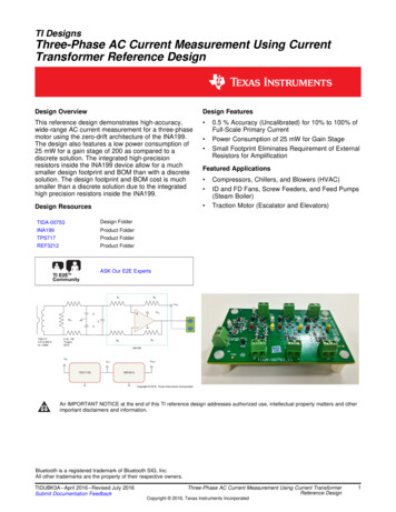
component (Φ0 0) as the prospective flux would at that timebe equal to zero – dashed grey curve. However, by applying itat UL(t) zero-crossing when the prospective flux would be atits peak value, it would experience the worst-case DCcomponent (Φ0 Φ0,max L·Um/Z) – solid black curve. Ofcourse, in above derivations no residual flux in the transformercore was assumed and consequently, Φ0 is in such case alwaysbetween -L·Um/Z Φ0 L·Um/Z. Also, due to impedance angleϴ being very close to π/4 it is clear that UL(t) is almost inphase with u(t).graph on Fig. 3. So to a certain extent, this can be thought ofas some kind of a self-regulating mechanism similar to selfregulating effect of power system load, which due to voltageand frequency drop usually decrease its power withdrawalfrom the grid [10]. Not only that, the decay of ΦDC(t) is clearlyfaster in the presence of non-linear magnetizing characteristic.Fig. 3. Transformer inductance voltage, magnetic flux and magnetizingcurrent in case of non-linear saturation characteristicFig. 2. System variables for circuit of Fig. 1 with respect to time for twotypical moments of transformer energizationAs long as our goal is merely understanding the reasonbehind the flux DC component ΦDC(t) occurrence, thesimplification of considering Lm (or in above derivation L, as L Lσ1 Lm) linear is more or less irrelevant. However, as soonas inrush currents are concerned, one has to keep in mind andsuitably consider that Lm is in fact nonlinear. Magnetizingcurrent im(t) is directly dependent on the non-linearity of Lm.This is why in order to simulate the actual phenomenon, a nonlinear saturation curve has to be incorporated into the model.In such case, high value of magnetic flux in the transformercore causes extremely high currents flowing throughtransformer winding (see lower graph on Fig. 3), which in turncause significant voltage drops on system impedance duringhigh current period – see upper graph on Fig. 3. Following(11) which describe the flux as being the integral of voltage,one can easily come to a conclusion that due to high currentsthe transformer core does not reach as much into saturationzone that would reach in case of e.g. Fig. 2 where Lm wasconsidered linear. The comparison can be seen on the secondAt this point, additional remark has to be discussedconcerning transformer saturation curve. Transformer no-loadtests usually provide a non-linear characteristic betweentransformer voltage and winding current. This data should notbe used for simulation purposes carelessly, as no-load testresults usually provide voltages and currents in RMS values.However, according to Fig. 3 (lower graph) the shape of thecurrent while transformer is in saturation is highly nonsinusoidal. While the voltage used in tests is said to be purelysinusoidal and therefore peak values can simply be obtained bymultiplying with 2, this is not the case with the current [11].Measuring equipment is not specially calibrated to expect suchextreme non-sinusoidal current conditions so measured RMScurrent values do not directly reflect the quantity ofmomentary currents values. This is why the no-load test curvehas to be converted into simulation-suitable form by e.g. usingan algorithm in [11].III. SYMPATHETIC INRUSH CURRENTA. DerivationsTransformer sympathetic inrush current is a consequence ofa sympathetic interaction between two or more transformers
operating in parallel, after applying a voltage source u(t) toone of them. A similar approach as for a single transformerenergization can therefore be performed for the derivation ofmagnetic flux of two parallel transformers. As only the DCflux component is responsible for transformer saturation, ACflux will be ignored in this section. Similar equivalent circuit isused for derivation of equations with the only differencehaving two unloaded transformers instead of just one (Fig. 4).The switching is performed on transformer T2, whereastransformer T1 is already energized. Again, currents on thesecondary winding of both transformers are assumed to bezero and the iron losses are also neglected. The situation isshown in Fig. 4, where the elements corresponding tosecondary winding and iron losses are again deliberatelydepicted in grey color, as they can be treated as inactive. Twoloop voltage equations (corresponding to two voltage loops,identified by denotations I. and II.) can be written in a similarmanner than (1): u ( t ) Rs R1,T1 i1,T1 Rs i1,T2 ((12))d Ls Lσ1,T1 Lm,T1 i1,T1 Ls i1,T2 0 dt R1,T1 i1,T1 R1,T2 i1,T2 ()d Lσ1,T1 Lm,T1 i1,T1 Lσ1,T2 Lm,T2 i1,T2 0dt (13)Renaming and merging individual transformer quantities(R1,T1 RT1, R1,T2 RT2, Lσ1,T1 Lm,T1 LT1, Lσ1,T2 Lm,T2 LT2) (12) and (13), considering the relation between themagnetic flux and the current L Φ/i, can be written in thefollowing matrix form: Φ& T 1 (t ) A11 A12 Φ T 1 (t ) B u (t ) & Φ T 2 (t ) A21 A22 Φ T 2 (t ) 142434243 14243 1&ΦARLR 2 Rsλ2 L 2 Lsλ1 whereas in general case when transformers T1 and T2 aredifferent they become: Ls ( RT1 RT2 ) LT2 ( RT1 Rs ) LT1 LT2 D L (R R )T1T2s λ1 2 LT1 LT2 ( LT2 Ls LT1 LT2 LT1 Ls )where 22 L2s ( RT1 RT2 ) L2T2 ( RT1 Rs ) R RR ()2T1T2T2D L2T1 L2T2 L2T1 ( RT2 Rs ) 2 LT1 Ls ( R R ) R T1T2s RT1 ( Ls RT1 ( LT
However, inrush current does not only affect the transformer being switched on. Instead, it has a significant impact also on all parallel connected transformers, which most certainly includes measurement transformers. This is known as a sympathetic inrush phenomenon. While the transformer being swit ched on might be a subject to a sudden high saturation level, the parallel transformers are .