Transcription
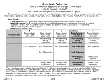
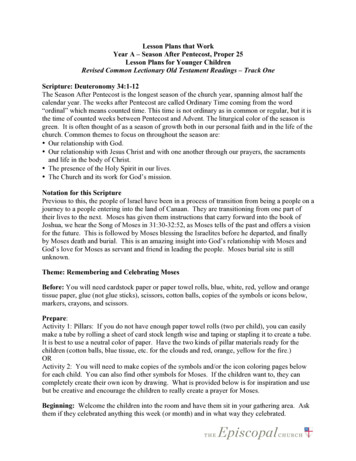
Plans for KioskRevised, Sep-12, 2016We have built three small kiosks for the Finger Lakes Land Trust in New York State. The kiosks aredesigned to be low-cost, attractive (in a natural/rustic fashion), functional, long-lasting, and maintenancefree. We also wanted to avoid the use of pressure-treated lumber and manufactured materials to thegreatest extent possible so that the kiosks would fit more comfortably in a natural setting. We believe thatwe have accomplished most of these objectives; time will tell on the “long-lasting, and maintenancefree.”Figure 1. The kiosk on the FLT at Sweedler Preserve at Lick BrookFigure 2. The kiosk at Kingsbury Woods Nature Preserve Copyright, 2016, Roger A. HopkinsRevised Sep-12. 2016Page 1These plans may be used for non-commercial projects only. No guarantees are included or implied. Include complete document if these plans areshared or copied. Please let me know about your project if you use these plans.
Figure 3. Kingsbury kiosk with trailhead register boxFigure 4. Kiosk at Bock-Harvey Nature PreserveAbout these plansThese are use-at-your-own-risk plans. We cannot be responsible for your results when usingthese plans.Drawings are not intended to be scale drawings.Quantities and descriptions in the bill of materials may be different for your project. Copyright, 2016, Roger A. HopkinsRevised Sep-12. 2016Page 2These plans may be used for non-commercial projects only. No guarantees are included or implied. Include complete document if these plans areshared or copied. Please let me know about your project if you use these plans.
Rough-cut Black Locust?We decided to build the kiosks using rough-cut black locust lumber. This helped us meet theobjectives of a natural, rustic appearance, and avoidance of pressure-treated lumber. Black locustis naturally rot-resistant. (We still find split black locust fence posts from the late 19th centuryalong the Finger Lakes Trail! They are like iron!)It may be difficult to find black locust cut to the dimensions you need. You will need to handselect virtually every piece since knots, cavities, and irregular dimensions are common. It isfairly easy to work when it is not well seasoned, but once seasoned, it is extremely hard. Youmust use carbide cutting tools. You must also pre-drill full length holes for your screws and usesoap on the threads to avoid breaking them off. Also, black locust is prone to warping andsplitting as it seasons, so it is important that you assemble a structurally sound kiosk withaccurate cuts so the pieces mate well. A final treat is that slivers from rough-cut black locust arequite nasty, and some have reported allergic reaction to the fine sawdust. Not to sound toonegative, once you have gotten used to working with black locust, you will find it an extremelystrong and beautiful wood capable of giving very satisfying results.Dimensional lumberIf you decide to use dimensional lumber, remember that a 2″ 4″ measures only 1½″ 3½″; youwill have to adjust some fastener lengths. Copyright, 2016, Roger A. HopkinsRevised Sep-12. 2016Page 3These plans may be used for non-commercial projects only. No guarantees are included or implied. Include complete document if these plans areshared or copied. Please let me know about your project if you use these plans.
The projectThere are three phases to the project.Selecting the woodPlan on spending several hours at the sawmill, and probably more than one trip. Make sure thatyou have gloves, a measuring tape, these plans, and a notebook. Black locust is heavy so don’tplan on using a roof rack for all of the lumber in one trip.Pre-fabricationThis involves building the leg and and working rafter sub-assemblies, and cutting all of theremaining pieces. You will want to do this in your shop and will need an accurate miter saw,power drill and appropriate bits. Mark pieces that are fitted together so they can be matched upduring construction. Plan on spending 8-10 hours in the shop.ConstructionYou will need at least one helper and preferably 2 or 3. Construction will probably take a fullday. If the holes and alignment go slowly, you may need part of a second day to finish.Here is the general order of business:1. Dig two holes. We try to keep the holes as small as possible using the undisturbed soilaround the holes for support and minimizing the amount of concrete or other fill. Butdon’t have the holes so small that you have trouble with alignment. Remember that youmay have to move the bottom of the leg as well as the top.2. Align the legs3. Attach the ridge beam and the horizontal panel brackets to the legs4. Fill in the holes5. Lunch6. Attach working rafter sub-assemblies to legs and ridge beam7. Attach bottom roof boards front and back8. Attach next two roof boards front and back9. Attach the lazy rafters to the ridge beam and the two roof boards front and back10. Attach the fourth roof boards front and back, then the ridge cap11. Finish the panel12. Finish the ground clean-upHere is what you will need at the site: Two six foot step ladders5′ Rock barWrecking bar or pry barPost-hole diggerShovel Copyright, 2016, Roger A. HopkinsRevised Sep-12. 2016Page 4These plans may be used for non-commercial projects only. No guarantees are included or implied. Include complete document if these plans areshared or copied. Please let me know about your project if you use these plans.
Pulaski or similar for light landscapingLoppers for cutting roots in the holesRake4-foot carpenter’s levelMeasuring tapesCarpenter’s square or other squaring toolMarkers and pencilsThree or four 1″ 3″ 12′ furring strips for bracesTwo 1″ 3″ 5′ furring strips for braces while aligning the legsSeveral blocks, for example 1″ 4″ 6″Four 24″ iron stakesHand sledgehammer, for driving stakes and nudging the alignmentClaw hammer or framing hammerClampsMore clampsStrong battery powered drill, drill bits, screw driver bits, and extra batteries. You willwant two drills for doing the roof, one with a drill bit and one with a screwdriver bit. Youcan pass them back and forth to two workers.Some way to keep the fasteners organized⅜″ Drill bit or auger for the carriage bolts.⅞″ Spade bit for countersinking the carriage boltsSocket wrenches for carriage boltsWater for the concreteGloves for all handsEye protection for all eyesHearing protection for all earsPlans, notebook, cameraOptional: Two sawhorses and table top of some sort to keep tools and materials off theground Copyright, 2016, Roger A. HopkinsRevised Sep-12. 2016Page 5These plans may be used for non-commercial projects only. No guarantees are included or implied. Include complete document if these plans areshared or copied. Please let me know about your project if you use these plans.
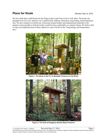
In the shopThe legsThe legs are made from girders fabricated (in your shop) from 2″ 6″, and 5/16″ 5″ lag screws or4½″ or 5″ structural screws. This construction will be almost as stiff as a 6 x 8 without theadditional weight or board foot cost. Also, the two pieces will work together to prevent warpingin the other piece. Finally, the cutouts for the ridge beam are much easier. (Note that thesecutouts are done before the pieces are screwed together.)The holes for the screws need to be pre-drilled for lag or construction screws, especially if thewood is seasoned. Measure and lay out the location of the screws carefully so that you end upwith a nice clean appearance. If using lag screws, first drill a 7/8″ diameter countersink holeabout the depth of the screw head. Then drill a pilot hole about 1/16 smaller than the screw. Ifusing structural screws, it may not be necessary to countersink the heads. You will probably haveto clamp the pieces together to get them to line up since the pieces will undoubtedly have somecurvature. Once clamped, drill all of the holes and put in the screws before loosening the clamps.4½″ structuralscrews (6-8 needed)Front2″ 6″ 10′10′Straight cutout forridge beam2″ 6″ 10′Figure 5. Leg sub-assemblyMake cutouts in the tops of the 2″ 6″ side leg pieces toreceive the ridge beam. These are easy to make with twocuts. The cutout should be 3″ deep with the width equal tothe thickness of the ridge beam (2″ if using rough-cut).Measure the width carefully so that the ridge beam will fitsnugly, but not too tight that you will have trouble atassembly time.2″ 6″2″ 6″As you make the cutouts, remember that the left and rightlegs are different. The drawing above shows both legs. Pickthe best sides (visually) of the leg pieces to face front and tothe sides.Cutout to receiveridge beamFront of kiosk Copyright, 2016, Roger A. HopkinsRevised Sep-12. 2016Page 6These plans may be used for non-commercial projects only. No guarantees are included or implied. Include complete document if these plans areshared or copied. Please let me know about your project if you use these plans.
The raftersCut the four working rafters that will connect from the Ridge to the rafter supports. Start with a24″ section of 2″ x 4″. Layout the angles and cut them with a miter saw. The miter cuts at thebottom end of the rafter are mainly cosmetic.1″Rafter30 Rafter support30 Figure 6. Relationship between rafter and rafter supportThe rafter supportsCut the two rafter supports. Start with a 44″ section of 2 x 4 and miter both ends at 60 . The 44”is a rough measurement that may vary depending on the thickness of the ridge beam, miterangles of the top of the rafters, and the vertical distance between the rafter support and the ridgebeam (see Figure 11 below). Make a rough layout of the rafters and the simulated ridge beambefore cutting the miters. If the rafter support is a bit short, simply raise it up slightly.30 4″44″Figure 7. Rafter support Copyright, 2016, Roger A. HopkinsRevised Sep-12. 2016Page 7These plans may be used for non-commercial projects only. No guarantees are included or implied. Include complete document if these plans areshared or copied. Please let me know about your project if you use these plans.
Build the rafter sub-assembliesIn this step, you will build the two rafter sub-assemblies each consisting of two rafters and therafter support. If you have space in your shop, the best way to do this is with a trial assembly ofthe kiosk frame. Otherwise you can lay out the sub-assemblies on a piece of scrap plywood asexplained in the next section.Trial Assembly1. Support the two leg assemblies on saw horses parallel and 4 feet apart. The front side ofthe legs should face the floor. Support the plywood display panel on clamped cleats (insetbelow) between the two legs to align the legs as they will be in the final assembly. Use 6foot pipe clamps (partially visible below) to clamp the assembly together.Figure 8. Trial assembly2. Insert the ridge beam into the cutouts inthe top of the legs and center it acrossthe width of the kiosk.3. Insert a 6″ construction screw throughthe side leg 2″ 6″ into the ridge beam(shown at right). This is temporary tokeep the trial assembly aligned. It willbe replaced in the field duringinstallation.Figure 9. Trial assembly detail Copyright, 2016, Roger A. HopkinsRevised Sep-12. 2016Page 8These plans may be used for non-commercial projects only. No guarantees are included or implied. Include complete document if these plans areshared or copied. Please let me know about your project if you use these plans.
Figure 10. Build rafter sub-assemblies from trial assembly4. Carefully align the rafters to the ridge beam and leg sub-assembly and clamp in place.5. Clamp a 4-foot piece of scrap (not shown) between the ends of the rafters to form a rigidtriangle.6. Fit the rafter support between the rafter ends making sure the support is perpendicular tothe leg.7. Clamp the rafter support to the leg.8. When everything is aligned correctly, drill pilot holes and then drive 4½″ constructionscrews to attach the rafter support and the top of the rafters to the legs. This should nowhold the rafters and the rafter support in alignment.9. Now working from the bottom of the rafter support, drill four countersink and pilot holesat an angle perpendicular to the rafters as shown in Figure 11.10. Drive the 4½″ and 6″ construction screws into each end of the rafter support to completethe rafter sub-assembly.11. Mark the location of the legs on the ridge beam to be used to align the structure in thefield. Also mark the top of the leg to be removed as shown in Figure 9.12. When finished, the screws holding the rafter sub-assembly to the legs and ridge beam canbe removed. They will be replaced in the field during installation. Copyright, 2016, Roger A. HopkinsRevised Sep-12. 2016Page 9These plans may be used for non-commercial projects only. No guarantees are included or implied. Include complete document if these plans areshared or copied. Please let me know about your project if you use these plans.
“Breadboard” layoutIf you do not use the trial assembly of the kiosk frame in the previous section, you can lay out therafter sub-assemblies on a small sheet of scrap plywood and do the build there.1. Lay the two rafters and the rafter support flat as shown below.2. Lay a short piece 2″ 4″ standing on edge between them (green below) to simulate theridge beam. This 2″ 4″ should be the same thickness (2″) as the actual ridge beam.Measure this carefully so that the ridge beam will fit snugly, but not too tight, duringinstallation. Use clamps or screws to anchor the 2″ 4″ to the plywood.3. Align the rafters so they fit against the simulated ridge beam as shown. Use screws at theupper end of the rafters to anchor the rafters firmly against the simulated ridge beam.These screw holes will be used to attach the rafter sub-assembly to the leg duringinstallation.4. Use clamps or temporary blocks (orange) at the lower ends of the rafters to prevent anymovement.5. Then lay the rafter support across as shown below in red. The 44″ width of the raftersupport was based on the ridge beam being exactly 2″ thick. If you have a differentthickness, or much variation in your rafters or your angles, you may have to trim theangled ends of the rafter support slightly.6. After checking that the rafter support is perpendicular to the simulated ridge beam andaligned with the rafters, use clamps or screws to anchor the rafter support to the plywood.The screw holes shown below are used to anchor the rafter support to the leg duringinstallation.7. Once the sub assembly is aligned, attach the rafter support to the bottom of both raftersusing 4½″ and 6″ construction screws.Temporary gauge forthickness of ridge beamTemporaryalignment blockRafterRafter supportFigure 11. Working rafters sub-assembly8. Repeat this process for the other end of the kiosk. Remember to match the thickness ofthe other end of the ridge beam. If there is much variation in your rafters, mark them andthe ridge beam once you have them fitted so you can match them up during assembly. Copyright, 2016, Roger A. HopkinsRevised Sep-12. 2016Page 10These plans may be used for non-commercial projects only. No guarantees are included or implied. Include complete document if these plans areshared or copied. Please let me know about your project if you use these plans.
“Lazy” raftersCut the remaining six “lazy” rafters in the same way that you cut the 4 working ones. The onlydifference is that you might consider using lighter weight 2″ 4″ stock. For example, if you findsome that are closer to 1½″ 3″, they will work just fine. Their only purpose is to hold the roofboards together; they are not supporting any weight. In fact, they are adding to the weight beingsupported by the roof boards. Also, the spacers are not needed.Roof capUse the best of the roof boards for the roof cap (¾″ 8″ 8′). Consider cutting drain grooves thelength of the roof cap as shown to prevent rain water from siphoning back under the roof cap.Roof capRidge board Roof boardRidge beamFigure 12 . Roof cap Copyright, 2016, Roger A. HopkinsRevised Sep-12. 2016Page 11These plans may be used for non-commercial projects only. No guarantees are included or implied. Include complete document if these plans areshared or copied. Please let me know about your project if you use these plans.
The display panelThe display panel has overall dimensions of 48″ wide and 36″ high. It is made from a sandwichof ½″ MDO plywood, ½″ Homosote Corkboard, and ⅛″ clear Lexan.Both the MDO and the Corkboard are a full 48″ 36″ inches and can be cut from a 4′ 8′ sheet.Since both are rather expensive, cut carefully. This will give you material for two kiosks withfactory cut sides and leave enough left over for a display panel of 4′ by slightly less than 2′. Thefactory cut sides on the 48″ 36″ are very useful for squaring up the legs and the panel brackets.The Lexan should be ordered cut to size and will be approximately 45½″ 33½″ to allow a 1¼″margin on all four sides for the frame. It is best to build the frame first and then measure theexact dimensions for the Lexan. Remember that you need allow a bit more than ⅛″ forhorizontal and vertical expansion. So for example, if your frame measures exactly 45½″ wide,order the Lexan 45⅜″ wide.2½″ od48″2″ 4″ Display brace(top and bottom)or1″ 3″ Display backing(left and right)Figure 13. Display panelDisplay panel frameMake the display panel frame from nicestraight pieces of 1″ x 2″ black locust. Youwill need two 36″ pieces and two 48″ pieces.Rip both sides to get a width of 1½″. Thenresaw the top and bottom to get a thicknessof ¾″.Cut rabbet groves along one side of thepieces ½″ wide and ¼″ deep as shownbelow. Cut 45 miters on the corners to fit toa frame measuring 36″ 48″.1½″¾″¼″½″Figure 14. Frame detail Copyright, 2016, Roger A. HopkinsRevised Sep-12. 2016Page 12These plans may be used for non-commercial projects only. No guarantees are included or implied. Include complete document if these plans areshared or copied. Please let me know about your project if you use these plans.
Display panel bracketsThere are horizontal brackets at the top and bottom of the display. These are made from two2″ 4″ 56″ pieces. They should be fairly straight, but can have imperfections on the back side oredges. Cut them a bit long and then trim to exact fit during construction.You will attach the horizontal brackets to the back of the legs inside the 2″ 6″ side members ofthe legs. Use four 3½″ deck screws. Use the MDO Plywood panel as a square to make sure thatthe legs are parallel, vertical, and exactly four feet apart measured from the inside edges of the2″ 6″ members. Then trim the horizontal brackets to length and clamp along the top and bottomof the MDO panel. Then drive the screws in the four corners from the back of the kiosk. Notethat the horizontal brackets are somewhat structural in addition to supporting the display panel.The vertical brackets serve only to provide an attachment point for the sides of the display panel.These are made from 1″ 6″ 28″ boards. Cut the boards a bit long and then trim to exact fitduring construction.You will attach the vertical brackets to the back of the legs between the two horizontal brackets.Use 4 or more 2½″ deck screws driving them from the back of the kiosk.2″ 4″ 56″Display bracket(2 needed)3½″ deck screws(from back)2½″ deck screws(from back)1″ 6″ 28″Display side bracket(2 needed)36″48″Figure 15. Installing the display panel Copyright, 2016, Roger A. HopkinsRevised Sep-12. 2016Page 13These plans may be used for non-commercial projects only. No guarantees are included or implied. Include complete document if these plans areshared or copied. Please let me know about your project if you use these plans.
On the siteAligning the structureThe main challenge in building the kiosk is getting the two legs vertical, parallel, and exactly 4′apart as measured from the inside edges of the legs. Additional complications are that the tops ofboth legs need to be at the same level, and the fronts of the two legs need to be in the same plane(in other words, not twisted with respect to each other).We have had the best luck with the followingsequence:1. First, try to get bottom of both holes atapproximately the same level. Do this byleveling a board between the two holes andthen measuring from the board to the bottomof each hole. If you find a slight difference,work with the less deep hole since the otherone can be filled in slightly. This will be thefirst leg. If there is a difference of more than afew inches (for example, you hit bedrock),then work with the deeper hole, planning tocut the bottom off of the other leg. (If youcan’t get both legs at least 24″ into the ground,consider moving to another location.)1st law of kiosk building: The hugeboulder or bedrock will always befound 20″ into the second hole.2. Put both legs in their holes.Figure 16. Aligning the legs3. Clamp one end of a 5′ furring strip to the frontface of the first leg. Then, with both legs approximately vertical, clamp the other end ofthe furring strip to the other leg. This will make sure that the fronts of both legs remain inthe same plane as you align the first leg.4. Make the first leg accurately vertical using a good carpenter’s level. The leg needs to bevertical left and right as well as front to back. Then use 1″ 3″ 12′ furring strips as bracesto hold the leg in position. One brace should be anchored well to the side and the otherwell to the back of the kiosk. Make sure that the side brace is in the plane of the front ofthe legs and that the back brace is 90 from that.5. Fit the ridge beam in place between the two legs and use it to level the tops of the legs.Measure any difference and then correct the second leg by filling in its hole or cutting offthe bottom of the leg (or deepening the hole) to brings the tops level.6. Check that the first leg is vertical and aligned in the plane of the front of the legs. Copyright, 2016, Roger A. HopkinsRevised Sep-12. 2016Page 14These plans may be used for non-commercial projects only. No guarantees are included or implied. Include complete document if these plans areshared or copied. Please let me know about your project if you use these plans.
7. Decide on the height of the display panel. Normally bottom of the panel is 3′ above theground. Clamp a block of wood at this height to the inside of the first leg to support thebottom corner of the MDO panel.8. Clamp a temporary support to the bottom edge of the MDO panel on the other side tohold the weight and keep it horizontal. Use a clamp on the first leg at the top of the MDOpanel to keep the panel vertical.9. With the MDO panel snugly against the first leg (and the first leg well aligned vertically)adjust the second leg using the MDO panel as a guide. This will make the second legvertical left to right. Use your carpenter’s level to get the second leg vertical front toback. You may need to move the bottom or the top to prevent twisting the legs out of thedesired plane.Figure 17. Aligning the tops of the legs (left) and squaring the legs using the MDO panel (right)10. At this point, the legs should be aligned. Clamp the second leg to braces or to the first legand MDO panel.11. Then with the legs aligned, adjust the left to right position of the ridge beam and attach it.Then trim the length of the horizontal panel brackets to actual measurement and attachthem. Clamp the horizontal panel brackets to the MDO panel to align them.12. Finally, fill the holes with concrete mix and water. Give the concrete a few minutes to setup before you begin working on the roof, and work carefully so as not to disturb thealignment until the concrete is well set.Some people like to pre-mix the concrete and pour it wet into the holes, while others pourthe concrete mix in dry and then add water into the hole. Others pour water into thebottom of the hole and then add dry concrete mix. Check out the quick-set concrete mix Copyright, 2016, Roger A. HopkinsRevised Sep-12. 2016Page 15These plans may be used for non-commercial projects only. No guarantees are included or implied. Include complete document if these plans areshared or copied. Please let me know about your project if you use these plans.
that is formulated for this technique; but be aware that it does set very quickly and youwill not have much time to correct any alignment problems.Some people prefer rocks, gravel, tightly packed soil, or rock dust rather than concrete toanchor the legs.The RoofRidge beamPosition the ridge beam in place and securewith 4″ deck screws through the frontmember of the leg assembly.4″ deckscrewFit the rafter sub-assembly into position onthe outside of the leg assembly. Align thetops of the rafters with the ridge beam andmake the rafter support level. Clamp therafter support to the leg. Repeat for the otherrafter subassembly.2″ 6″LegassemblyFRONT2″ 6″Figure 18. Install the ridge beamWhen rafter subassemblies are aligned, tighten the clamps and insert 3½″ deck screws throughthe top of the rafters into the legs. Drill the holes for the two carriage bolts. Countersink the nuts.Insert and tighten the carriage bolts. Finally, put two 4″ deck screws through the top of the raftersinto the ridge beam. Note where these screws are so you don’t hit them when attaching the roofand the ridge cap.4″ deckscrews¾″ 4″ 8′ridge board⅜ 4″carriage boltFRONT2″ 6″3½″ deckscrews2″ 6″Figure 19. Install the rafter sub-assembliesAttach the ridge board to the ridge beam using two 4″ deck screws. Drive the screws between therafter locations so they don’t interfere with the other screws. Copyright, 2016, Roger A. HopkinsRevised Sep-12. 2016Page 16These plans may be used for non-commercial projects only. No guarantees are included or implied. Include complete document if these plans areshared or copied. Please let me know about your project if you use these plans.
Figure 20. Roof constructionStart the roof at the bottom by clamping the #1 roof board (Figure 21) to the two front rafters.Then drive a 4″ deck screw through the roof board into the rafter. Attach the #1 board to the backrafters in the same way. This will prevent the ends from twisting as you build the roof.Then do a rough layout of the next three roof boards in the front and back. You want the overlapsto be about the same and the top roof board snug up against the ridge board. Mark the position ofthe boards and then work from the bottom up by clamping the #2 board to the two end rafters,and then securing with a 4″ deck screw. Do only #2 board front and back now; you will do the #3and #4 boards front and back after the lazy rafters are in place. IMPORTANT: Drill pilot holesfor all roof board screws and drive the screws for boards #2, #3, and #4 near the contact pointwith the board below and the rafter (screw locations shown in red below will cause the roofboards to split).¾″ 8″ 8′roof board¾″ 8″ 8′roof cap4″ deckscrews¾″ 4″ 8′ridge board FRONT2″ 6″ 2″ 6″Figure 21. Attaching roof boards Copyright, 2016, Roger A. HopkinsRevised Sep-12. 2016Page 17These plans may be used for non-commercial projects only. No guarantees are included or implied. Include complete document if these plans areshared or copied. Please let me know about your project if you use these plans.
Clamp the lazy rafters to the #1 roof board and align the upper end with the ridge beam. Securethe lazy rafter to the ridge beam with a 4″ deck screw (see Figure 19 for screw location). Thenwith the clamp still in place, drive the 4″ deck screws through the #1 and #2 roof boards into thelazy rafter. Repeat for the all of the lazy rafters.“Working” rafters“Lazy” raftersFigure 22. Attaching “lazy” raftersTo complete the roof, attach the third and fourth roof boards front and back, and then screw theridge cap down through the ridge board into the ridge beam. Use five 4″ deck screws along thelength of the ridge, offset slightly from the rafters to avoid interfering with the other screwsalready in place.Attach the ¾″ 4″ 8′ roof cap by driving several 4″ deck screws down into the ridge beam.Roof tipsBefore attaching the roof cap, consider cutting drip grooves as shown in Figure 12. On one kioskwe had a slight problem with water siphoning back under the roof cap that this should prevent.If there are gaps between the roof cap and the #4 roof board or any other potential leak spots, youcan also use some high quality silicone caulking.Several kiosks have been built with this plan with a more conventional roof of flat boards,membrane, and cedar shingles. This adds a bit to the cost and gives the kiosk a somewhat lessrustic look. The roof cap is not used. Copyright, 2016, Roger A. HopkinsRevised Sep-12. 2016Page 18These plans may be used for non-commercial projects only. No guarantees are included or implied. Include complete document if these plans areshared or copied. Please let me know about your project if you use these plans.
Maintaining the Display panelYou will need to instruct the person responsible for the content of the display panel, and providethem with the proper driver for the trim screws. Here is how to remove the Lexan: Remove all ofthe screws from the vertical frame piece on the right side of the panel. Remove the frame pieceand set it aside. Slide the Lexan sheet slightly to the right so that it is free from the left side framepiece. Then lift the horizontal center of the Lexan away from the corkboard to buckle the sheetenough to free it from the top frame piece. You can then remove the Lexan sheet and carefullyset it aside. Reverse the process after changing the content. An office stapler is probably the bestway to attach paper to the cork board. Hopefully, it should not be necessary to laminate thecontent.Kadillac KioskThe kiosk shown below was professionally designed and was constructed and installed usingsimilar techniques to those described above. The kiosk features two profess
3. Attach the ridge beam and the horizontal panel brackets to the legs 4. Fill in the holes 5. Lunch 6. Attach working rafter sub-assemblies to legs and ridge beam 7. Attach bottom roof boards front and back 8. Attach next two roof boards front and back 9. Attach the lazy rafters to the ridge