Transcription
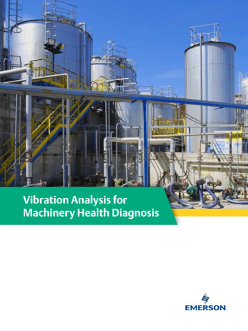
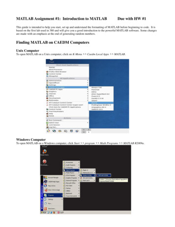
Using MATLAB for Vibration MeasurementsVibration measurements are critical in predictive maintenance and diagnostic fault testing applications for quality assurance. This white paper describes the following topics that are important when choosing a vibrationmeasurement solution: Sensor Considerations Data Acquisition Hardware ConsiderationsSigma-Delta A/D ConvertersSimultaneous InputsAC Coupling Data Acquisition Software ConsiderationsConfiguring your External HardwareAcquiring Data from two Triaxial AccelerometersReading Data into MATLAB for Immediate AnalysisGenerating Reports and ApplicationsSensor ConsiderationsTypical vibration applications use IEPE (ICPTM) accelerometers to measurevibration. An accelerometer consists of a piezoelectric element connected toa known mass. When the accelerometer is vibrated, the mass applies force tothe piezoelectric element, generating an electrical charge that is proportionalto the applied force. You can then measure this charge to determine vibration characteristics.www.datatranslation.com1
A wide range of IEPE accelerometers are available, including those thatmeasure along only one axis and those that measure up to three axes simultaneously, called triaxial accelerometers. Different mounting options andmeasurement ranges are available to suit your application.When choosing a vibration measurement solution, ensure that your data acquisition system supports direct connection of IEPE inputs, and that themeasurement range of your sensor is within the input range of your data acquisition system. For example, if you want to measure a 6 V input signal,the full-scale input range of your system should exceed 6 V. In addition, ifyou are using a triaxial accelerometer, ensure that your data acquisitionsupports simultaneous acquisition of up to three IEPE inputs so that youcan correlate measurements on all three axes.F M xAMost accelerometers require a currentsource of 4 mA and a compliance voltageof at least 18 V to drive their internal circuitry. Other accelerometers require a 2mA current source, but have limitations incable length and bandwidth. Ensure thatyour data acquisition system supports therequirements of your sensor.Mass (M)OutputPiezoelectric ElementVibratory Acceleration (A)Data AcquisitionSystemVibrationHow Accelerometers WorkData Acquisition Hardware ConsiderationsWhen choosing data acquisition hardware for vibration applications, thefollowing hardware considerations are important: Sigma-Delta A/Ds Simultaneous A/Ds AC Couplingwww.datatranslation.com2
Sigma-Delta A/DsMost vibration measurement applications require a data acquisition systemwith an antialiasing filter in the A/D circuitry to eliminate unwanted frequencies in the measurements. Sigma-Delta A/Ds have anti-aliasing filtersbuilt-in. Sigma-Delta converters offer the following advantages, makingthem ideal for vibration measurement applications: Reduce noise and improve accuracy by oversampling each input. Eliminate errors that result from aliasing and high frequency noise by using a built-in decimation filter. Provide excellent low-level signal-to noise performance, which improvesdynamic accuracy on low-level signals. Provide excellent differential linearity, which ensures consistently accurate data conversion across the full input range of the signal.For precise measurements, 24-bit Sigma-Delta A/Ds are also desirablesince they allow you to measure the full dynamic range of the input sensors.Simultaneous A/DsSimultaneous sampling increases the bandwidth of signals that you can accurately measure, while eliminating several sources of error, including timeskew and cross-talk between channels.One A/D converter per channel increases the module's overall sampling frequency (when compared to multiplexed architectures) and increases thesignal bandwidth that you can acquire. For example, if your module provides a sampling frequency of 100 kHz per channel, then according to Nyquist, you can accurately measure up to 50 kHz on each channel when using a simultaneous A/D architecture. In contrast, in multiplexed architectures, the usable signal bandwidth decreases with every additional channelyou measure.www.datatranslation.com3
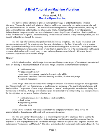
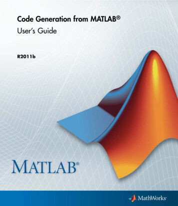
With a simultaneous A/D architecture, all signal inputs are sampled at theexact same instant in time, therefore, any channel skew, cross-talk, and settling time problems are also virtually eliminated, allowing you to measurehighly accurate data at high speeds.SimultaneousSamplingeliminates time skewbetween channelsand simplifies bothtime and frequencybased ngmay require softwarecorrection fordetecting certainpatternsThe DT9837 and DT9841-VIB USB module from Data Translation provideup to 8, 24-bit Sigma-Delta converters for precise, simultaneous analog inputmeasurements.www.datatranslation.com4
AC CouplingTo measure low frequency signals accurately at the Nyquist sampling rate,it is important that your anti-aliasing filter supports a wide passband toeliminate unwanted high frequency components.An ideal anti-aliasing filter passes all signals in the band of interest andblocks all signals outside of that band. However, in practical use, the rolloff characteristics of the antialiasing filter allow some signals to passabove the filter’s cutoff frequency. By using AC coupling, you can eliminate any DC that may pass through the anti-aliasing filter, thereby, maintaining the integrity of your signal. As shown below, the low frequencybreakpoint of 0.5 Hz allows very low frequency measurements.Data Translation’s DT9837 and DT9841-VIB modules provide software- selectable AC and DC coupling. When AC coupling is selected, the modules eliminateany DC that may pass through the anti-aliasing filter. The excellent “brick wall”anti-alias filter eliminates unwanted high frequency interference.www.datatranslation.com5
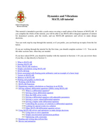
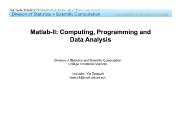
Data Acquisition Software ConsiderationsWhen choosing software for data acquisition and analysis, the followingconsiderations are important: Support for a wide array of data acquisition hardware Strong data analysis libraries Scripting that is easy to read, modify, and debug Application development support Report generation to share resultsMATLAB is a well known interactive software environment for data acquisition and analysis, report generation, and test system development.MATLAB provides a complete set of tools for acquiring and analyzing analog and digital I/O signals from a variety of PC-compatible data acquisitionhardware. The MATLAB Data Acquisition Toolbox lets you configure yourexternal hardware devices, read data into MATLAB and Simulink for immediate analysis, and send out data for controlling your system.The diagram below depicts an example using MATLAB and the MATLABData Acquisition Toolbox with Data Translation’s DT9837 to acquire vibration data from USB modules. Notice that the Data Translation provides aninterface layer, called the DAQAdaptor for MATLAB, which allows the MATLAB Data Acquisition Toolbox to communicate with Data Translation’s hardware. While the Data Acquisition Toolbox is collecting data, MATLAB can analyze and visualizethe data.www.datatranslation.com6
MATLABData AcquisitionToolboxData Translation’sDAQ Adaptor forMATLABData Translation’sData AcquisitionUSB ModulesIEPE SensorsWhile the Data Acquisition Toolbox is collecting vibrationdata from the USB module, MATLAB can analyze andvisualize the data.www.datatranslation.com7
The following sections describe in detail how you can use MATLAB tomeasure vibration data from two triaxial accelerometers using two DataTranslation DT9837 USB data acquisition modules, and display the results.This example uses the MATLAB Data Acquisition Toolbox with Data Translation’s USB modules to measure and analyze vibration data in one integrated environment.Configuring Your External HardwareTo configure your external hardware, first connect the X, Y, and Z outputsof one accelerometer to analog input channels 0, 1, and 2 of the firstDT9837 module. Then, connect the X, Y, and Z outputs of the second accelerometer to analog input channels 0, 1, and 2 of the second DT9837 module. If you want to start acquisition on both modules simultaneously, connect a shared external digital TTL trigger input to both modules. A risingedge on the external trigger input will start the acquisition on both modules.www.datatranslation.com8
In MATLAB, set up your script as follows to finish configuring your system:% Register Data Translation’s DAQ Adaptor for MATLABdaqregister (‘dtol’);% Create an analog input object to communicate with each% DT9837 module (AI0 corresponds to the first module; AI1% corresponds to the second module)AI0 analoginput(‘dtol’, 0);AI1 analoginput(‘dtol’, 1);% Add A/D channels 0, 1, and 2 – one channel for each axis of the accelerometer –% to each analog input objectaddchannel(AI0, 0:2);addchannel(AI1, 0:2);% For each DT9837 module, configure A/D channels 0, 1, and 2 forIEPE inputs;% each channel uses a 4 mA current source and AC couplingAI0.channel.ExcitationCurrentSource ‘Internal’;AI0.channel.Coupling ‘AC’;AI1.channel.ExcitationCurrentSource ‘Internal’;AI1.channel.Coupling ‘AC’;% Configure the external digital trigger (rising edge) for each DT9837moduleset([AI0 AI1], ‘TriggerType’, ‘HwDigital’);set([AI0 AI1], ‘TriggerCondition’, ‘Rising’);% When a trigger is detected, continuously acquire data until a stopfunction is% issued or until an error occursset([AI0 AI1], ‘SamplesPerTrigger’, inf);% Configure the clock for the each DT9837 module, setting the clockrate to the% maximum clock rate supportedmaxRate daqhwinfo(AI0, MaxSampleRate);set([AI0 AI1], ‘SampleRate’, maxRate);% Allocate memory to store the datawww.datatranslation.com9
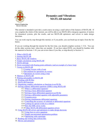
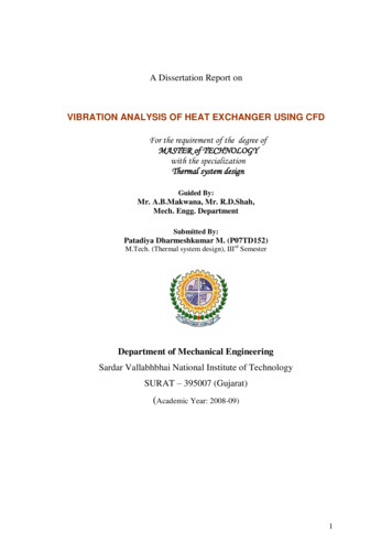
set([AI0 AI1], ‘BufferingConfig’, [1000 5]);% Define the number of samples (10000, in this case) to acquire foreach channelset([AI0 AI1], ‘SamplesAcquiredFcnCount’, 10000);% When 10000 samples have been acquired for each channel,% define the function to call to plot the dataset(AI0, ‘SamplesAcquiredFcn’, {@plotData0});set(AI1, ‘SamplesAcquiredFcn’, {@plotData1});Acquiring Data from Two Triaxial AccelerometersOnce you have wired your external hardware and configured it in MATLAB, start the analog input objects using the following script in MATLAB:% Start the analog input objects on both modulesstart([AI0 AI1]);When a rising edge of the shared digital trigger is detected on each module, acquisition begins. The data is acquired from all six IEPE inputs at themaximum clock rate of the device, and the data is stored in the memoryyou allocated.Reading Data into MATLAB for Immediate AnalysisWhen 10,000 samples are acquired on each input channel, the callbackfunctions you referenced previously (plotData0 and plotData1) are called.These functions read the data into MATLAB and plot it for immediateanalysis.Callback functions plotData0 and plotData1 are defined as follows:% Get the data from the first DT9837 module into MATLAB and plotall% three channels separately.function plotData0(Obj, event)AI0 Obj;data getdata (AI0, 10000);ch0a data data(:,1);subplot(3,2,1); plot(ch0a data)www.datatranslation.com10
Data acquired and plotted in MATLAB for immediate analysis.Generating Reports and ApplicationsA report can be automatically generated from the MATLAB script if it iswritten in the MATLAB Editor. To generate the report, press the Publish toHTML button in the editor. (Other formats are available.) Pressing this button will execute the MATLAB script and embed the script’s contents alongwith all plots generated in a single HTML file that can be viewed andshared.MATLAB provides a GUI development tool called GUIDE that allows youto incorporate the MATLAB script in a graphical application. Press theGUIDE button in MATLAB to launch this tool.ConclusionWhen choosing a solution to measure vibration, consider the IEPE sensorsyou need and their requirements, the capabilities of your USB data acquisition hardware, and the analysis software you’ll need to accomplish yourgoals. This paper described an example that used the MATLAB Data Acquisition Toolbox with Data Translation’s DT9837 USB modules and DAQAdaptor for MATLAB to provide a complete solution for measuring andanalyzing sound and vibration.www.datatranslation.com11
For More Information1. Using DT9837 hardware: http://www.datx.com/products/dataacquisition/usb/ prod dt9837.htm2. Using MATLAB: http://www.mathworks.com/products/matlab3. Using MATLAB Data Acquisition Toolbox: http://www.mathworks.com/products/daq4. Using the DAQ Adaptor for MATLAB: http://www.datatranslation.com/products software/dt-matlab-interface-tools.htmTrial of MATLAB and MATLAB Data Acquisition ATLAB Script used in this example:www.matlabcentral.comMATLAB is a registered trademark of The MathWorks, Inc.Copyright 2007 Data Translation, Inc. All rights reserved.www.datatranslation.com12
Data Acquisition Toolbox with Data Translation’s DT9837 to acquire vibra-tion data from USB modules. Notice that the Data Translation provides an interface layer, called the DAQ Adaptor for MATLAB, which allows the MATLAB Data Acquisition Tool-box to communicate with Data Translation’s hardware. Wh