Transcription
Summary of the Stray Light Study 2014– measurements for correcting X-ray images –2-September, 2014 by Aki Takeda
1. Introduction9-May-2012 : Ti-poly image blurring noticed.First noticed in June as sudden rise of G-band intensity.(cf : PPT file by DeLuca, McCauley, et al. 22-Jun-2012)
Our current understanding of the phenomena :caused by an XRT pre-filter failure (pinhole). visible stray light contaminating X-ray images. Yohkoh/SXT suffered the same failure in 1993, sopresumably, corrected by the same method as SXT. Use terminator images for correction.Take image with X-ray filter during Day to Night(or N to D) transition of the spacecraft.X-ray component is completely absorbed by theatmosphere while passing through the long optical path.Visible light component starts to decay some time afterthe extinction of the X-ray.There exists a short period of time ( 30 sec for SXT)when the visible light component is purely detectedthrough the X-ray filter ( stray light image).
Difference between XRT and SXT cases:XRTSXTOrbitSun synchronousLow inclined (31 deg.)Eclipse seasonMay to mid-AugustAll yearTwilight frequencyEvery 98 min. (2014.8)Every 97 min. (1997.9)Twilight (D to N) duration5 to 10 min.Typically 100 sec.Data acquisition window1 to 3 min.Typically 20 sec.XRT stray light images can be taken only during limitedmonths. However, the condition of data acquisition for each twilight eventis better in XRT than SXT.
2. XRT Stray light measurement – 2014.2.1. Basic structure of observing programs :(1) Full-Sun images before twilight (1024x1024, with therelevant filter, with multiple exposures, use synopticobs., if available) . These are Images to be corrected.(2) Monitor images for light curve (256x256, in G-bandand Ti-poly, centered on AR or bright structures, every10 seconds, from 30 sec before the twilight to 30 secafter entering the night). Important to be sure the straylight images were taken at the right timing.(3) Stray light image (1024x1024, with the relevant filter,DPCM, every 60 sec, starting a few minutes after thetwilight through the night entry).
2.2 Dates of measurement and purposesTimeline No.Date & Time (UT)Purposes12014/05/06 17:40Collect Light Curve, Ti-poly (250 msec) at Disk Center22014/05/15 18:20LC, Ti-poly (1.41 sec) & Al-mesh (707 msec) at DC32014/05/27 20:30LC, Al-poly (1.00 sec) & C-poly (1.41 sec) at DC42014/07/03 18:30LC, Ti-poly (1.41 sec) & Thin-Be (2.83 sec) at DC52014/07/30 18:30LC, Med-Al (32 sec) at DC2014/07/31 15:49LC, Med-Be (24 sec) at DC2014/07/31 17:27LC, Thick-Al (64 sec) at DC2014/08/01 16:26LC, Thick-Be (64 sec) at DC2014/08/08 18:56LC, Ti-poly (4.00 sec) & C-poly (4.00 sec) at N-pole2014/08/08 20:40LC, Ti-poly (1.41 sec) & C-poly (1.41 sec) at E-limb2014/08/08 22:30LC, Ti-poly (4.00 sec) & C-poly (4.00 sec) at S-pole67
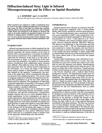
3. Results(1) Out of 9 X-ray analysis filters, significant visible straylight components were detected only with the Ti-polyand C-poly filters. Ti-poly (at DC pointing) C-poly (at DC pointing)[XRT20140515 182503.4.fits][XRT20140527 204601.0.fits]
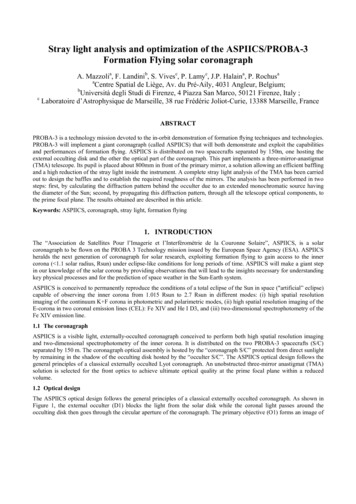
(2) Stray-light images consist of 3 components: Solar disk component (brightest).Ti-poly disk is 2.5 times brighter than C-poly's. Structures particular to each filter.Ti-poly: tree-ring-like shape (stable with time and pointing).C-poly: wavy streak-like (pointing dependent). Dark component (weakest contribution).Rapid changing periodic stripes similar to those foundin dark frames.(3) At the polar- and limb-pointings, stray-light imagesare different most significantly in the solar diskcomponent.
Stray-light images at N-pole, E-limb, and S-pole pointings. Ti-polyXRT20140808 191124.0.fits C-polyXRT20140808 191137.1.fitsXRT20140808 205020.5.fits XRT20140808 222905.4.fitsXRT20140808 205031.0.fitsXRT20140808 222918.5.fits
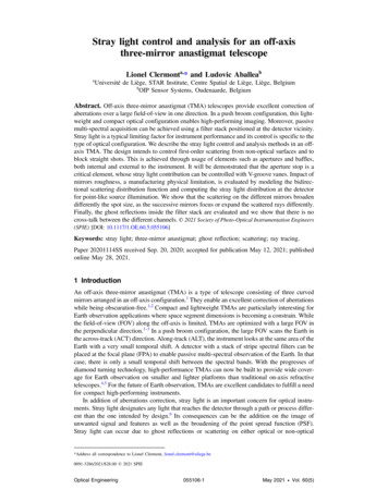
(4) Stray-light images are good for quantitative correctionof X-ray coronal images taken closely in time with andat the same pointing as the stray-light image.[Things to consider to correct other images] Pointing of the stray-light image needs to be the same as theimage to be corrected.Long term variation of the stray-light intensity. (Stray-light in May2014 is approximately twice the level in May-2012.)Reproducibility of the pointing. (Seasonal change of the offsetbetween Hinode and XRT, typically 10 to 30 arcsec.)
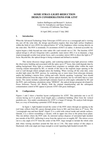
Examples of image correction (top: before corr., bottom: after corr.)Ti-poly at DCC-poly at N-poleTi-poly at S-pole
Our current understanding of the phenomena : caused by an XRT pre-filter failure (pinhole). visible stray light contaminating X-ray images. Yohkoh/SXT suffered the same failure in 1993, so presumably, corrected by the same method as SXT. Use terminator images for correction. Take image with X-ray filter duri