Transcription
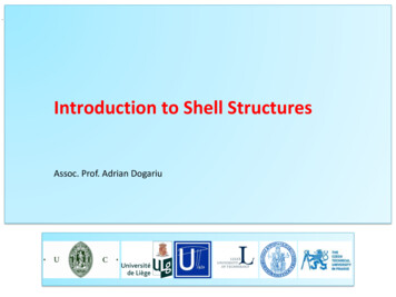
EUROCODESBackground and ApplicationsCold-Formed Structures (Part 1.4)Brussels, 18-20 February 2008 – Dissemination of information workshopCold-Formed (CF) StructuresEurocode 9 - Part 1.4Prof. Raffaele LandolfoUniversity of Naples “Federico II”1
EUROCODESBackground and ApplicationsCold-Formed Structures (Part 1.4)Brussels, 18-20 February 2008 – Dissemination of information workshop2Part 1. Introduction1.1 TYPES AND SHAPES1.2 COLD–FORMING TECHNIQUES1.3 BEHAVIOURAL FEATURES1.4 TYPES OF LIGHT-WEIGHT STRUCTURESPart 2. Design of aluminium CF structures according to EC92.1 GENERAL INFORMATIONS2.2 GENERAL RULES FOR LOCAL BUCKLING RESISTANCEPART 1.1 (EN 1999-1-1)2.3 GENERAL RULES FOR COLD-FORMED SHEETINGPART 1.4 (EN 1999-1-4)Prof. Raffaele Landolfo - University of Naples “Federico II”
EUROCODESBackground and ApplicationsCold-Formed Structures (Part 1.4)Brussels, 18-20 February 2008 – Dissemination of information workshop3Part 1.IntroductionProf. Raffaele Landolfo - University of Naples “Federico II”
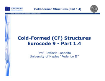
EUROCODESBackground and ApplicationsCold-Formed Structures (Part 1.4)Brussels, 18-20 February 2008 – Dissemination of information workshop41.1 TYPES AND SHAPESCold-formed (CF) structural products can be classified into three main typologies: members sheeting sandwich panelsStructural members aremainly used in the higherrange of thickness, asbeams for comparativelylow loads on small spans(purlins and rails), ascolumns and verticalsupports, and as bars intrusses.The depth of CF membersranges from 50 to 300 mmand the thickness ofmaterial ranges from 1.0to 8.0 mm, although depthand thickness outsidethese ranges also are usedProf. Raffaele Landolfo - University of Naples “Federico II”
EUROCODESBackground and ApplicationsCold-Formed Structures (Part 1.4)Brussels, 18-20 February 2008 – Dissemination of information workshop51.1 TYPES AND SHAPESCold-formed (CF) structural products can be classified into two main typologies: members sheeting sandwich panelsSheeting are plane loadbearing members inthe lower range ofthickness, generallyused when a spacecovering function undermoderate distributedloading is needed, e.g.roof decks, floor decks,wall panels.The depth of panelsgenerally ranges from40 to 200 mm and thethickness of materialranges from 0.5 to 2.0mm.Prof. Raffaele Landolfo - University of Naples “Federico II”
EUROCODESBackground and ApplicationsCold-Formed Structures (Part 1.4)Brussels, 18-20 February 2008 – Dissemination of information workshop61.1 TYPES AND SHAPESThree generations of sheeting1st generationThe first generation includes planetrapezoidal profiles withoutstiffeners, allowing spans betweensecondary members of no morethan 3 m.2nd generationIn the second generation thetrapezoidal sheets are stiffened inlongitudinal direction byappropriate folding and may spanup to 6 - 7 m.3rd generationThe third generation profiles aretrapezoidal units with bothlongitudinal and transversalstiffeners, which provide suitablesolution for spans up to 12 mwithout purlins.Prof. Raffaele Landolfo - University of Naples “Federico II”
EUROCODESBackground and ApplicationsCold-Formed Structures (Part 1.4)Brussels, 18-20 February 2008 – Dissemination of information workshop71.1 TYPES AND SHAPESCold-formed (CF) structural products can be classified into two main typologies: members sheeting sandwich panelsThe prefabricated sandwichpanels are particularlysuitable because theyprovide thermal insulationat the same time as thebasic weather shieldIt consists of two metalfaces bonded to an internallayer of rigid foamSuch panels may beinstalled very quickly thussaving time on siteProf. Raffaele Landolfo - University of Naples “Federico II”
EUROCODESCold-Formed Structures (Part 1.4)Background and ApplicationsBrussels, 18-20 February 2008 – Dissemination of information workshop81.2 COLD – FORMING TECHNIQUESCF sections can be generally obtained through two manufacturing methods:1.continuous process: cold - rollingThe process of cold-rolling is widely used for theproduction of individual structural members andcorrugated sheeting. The final required shape isobtained from a strip which is formed gradually,by feeding it continuously through successivepairs of rolls which act as male and female dies.2.discontinuous process: press braking or foldingIn these processes, short lengthsof strip are fed into the brakeand bent or pressed roundshaped dies to form the finalshape. Usually each bend isformed separately and thecomplexity of shape is limited tothat into which the die can fit.Press brakingFoldingProf. Raffaele Landolfo - University of Naples “Federico II”
EUROCODESBackground and ApplicationsCold-Formed Structures (Part 1.4)Brussels, 18-20 February 2008 – Dissemination of information workshop1.39BEHAVIOURAL FEATURESIf compared with conventional metallic member, thin-walled CF elements aremainly characterised by:1.2.3.the constant thickness of the formed sectionthe relatively high width-to-thickness ratio of the elementsthe variety of cross-sectional shapesThe feature 2. gives rise to local buckling phenomena, which penalise theload-bearing capacity.As a consequence, structural analysis and design of thin-walled CF elements isgenerally complicated by the effects arising from the above features, which donot affect the structural response of more simple and compact sections.Prof. Raffaele Landolfo - University of Naples “Federico II”
EUROCODESBackground and ApplicationsCold-Formed Structures (Part 1.4)Brussels, 18-20 February 2008 – Dissemination of information workshop1.310BEHAVIOURAL FEATURESThe main aspects that influence the structuralbehaviour of thin-walled sections are: local buckling of the compression parts interaction between local and overall buckling modes shear-lag and curling effects effects of cold-forming processBesides, since CF sections are generally thinwalled and of open cross-section,torsional-flexural buckling may be the criticalphenomenon influencing the designProf. Raffaele Landolfo - University of Naples “Federico II”
EUROCODESBackground and ApplicationsCold-Formed Structures (Part 1.4)Brussels, 18-20 February 2008 – Dissemination of information workshop111.4 TYPES OF LIGHT-WEIGHT STRUCTURESEarly applications of CF thin-walled aluminium sections were restricted tosituations where weight saving was important. With the advance in the rawmaterial itself and the manufacturing processes, the range of actual andpotential use is virtually unlimited.The main structural typologies are: Industrial building Housing Temporary structuresProf. Raffaele Landolfo - University of Naples “Federico II”
EUROCODESBackground and ApplicationsCold-Formed Structures (Part 1.4)Brussels, 18-20 February 2008 – Dissemination of information workshop121.4 TYPES OF LIGHT-WEIGHT STRUCTURESIndustrial buildingTrusses made of CF members may be found in industrial and storage buildings.The main chords are usually channel sections joined back to back.The web members are normally single channels.Prof. Raffaele Landolfo - University of Naples “Federico II”
EUROCODESBackground and ApplicationsCold-Formed Structures (Part 1.4)Brussels, 18-20 February 2008 – Dissemination of information workshop131.4 TYPES OF LIGHT-WEIGHT STRUCTURESIndustrial buildingProf. Raffaele Landolfo - University of Naples “Federico II”
EUROCODESBackground and ApplicationsCold-Formed Structures (Part 1.4)Brussels, 18-20 February 2008 – Dissemination of information workshop141.4 TYPES OF LIGHT-WEIGHT STRUCTURESIndustrial buildingProf. Raffaele Landolfo - University of Naples “Federico II”
EUROCODESBackground and ApplicationsCold-Formed Structures (Part 1.4)Brussels, 18-20 February 2008 – Dissemination of information workshop151.4 TYPES OF LIGHT-WEIGHT STRUCTURESIndustrial buildingAluminium extruded productsProf. Raffaele Landolfo - University of Naples “Federico II”
EUROCODESBackground and ApplicationsCold-Formed Structures (Part 1.4)Brussels, 18-20 February 2008 – Dissemination of information workshop161.4 TYPES OF LIGHT-WEIGHT STRUCTURESTemporary structuresModular unit for houses, offices, construction site accommodation, etc., mayconveniently be produced using CF sections and flat products.vMotorized roofing for concert stage (Europoint s.n.c.)Prof. Raffaele Landolfo - University of Naples “Federico II”
EUROCODESBackground and ApplicationsCold-Formed Structures (Part 1.4)Brussels, 18-20 February 2008 – Dissemination of information workshop171.4 TYPES OF LIGHT-WEIGHT STRUCTURESTemporary structuresMotor show Bologna, Italy - (Europoint s.n.c.)Prof. Raffaele Landolfo - University of Naples “Federico II”
EUROCODESBackground and ApplicationsCold-Formed Structures (Part 1.4)Brussels, 18-20 February 2008 – Dissemination of information workshop181.4 TYPES OF LIGHT-WEIGHT STRUCTURESTemporary structuresPrefabricated industrial hangar - (CoverTech)Prof. Raffaele Landolfo - University of Naples “Federico II”
EUROCODESBackground and ApplicationsCold-Formed Structures (Part 1.4)Brussels, 18-20 February 2008 – Dissemination of information workshop191.4 TYPES OF LIGHT-WEIGHT STRUCTURESHousingWith regards to housing in CF members, this development is being led by theUSA, but interesting applications are coming up also in Europe. The primaryframing elements for this construction system are cold-formed metallic wallstuds and floor joists.Prof. Raffaele Landolfo - University of Naples “Federico II”
EUROCODESBackground and ApplicationsCold-Formed Structures (Part 1.4)Brussels, 18-20 February 2008 – Dissemination of information workshop201.4 TYPES OF LIGHT-WEIGHT STRUCTURESHousingProf. Raffaele Landolfo - University of Naples “Federico II”
EUROCODESBackground and ApplicationsCold-Formed Structures (Part 1.4)Brussels, 18-20 February 2008 – Dissemination of information workshop21Part 2.Design of aluminiumCF structures according to EC9Prof. Raffaele Landolfo - University of Naples “Federico II”
EUROCODESBackground and ApplicationsCold-Formed Structures (Part 1.4)Brussels, 18-20 February 2008 – Dissemination of information workshop222.1 General informationProf. Raffaele Landolfo - University of Naples “Federico II”
EUROCODESBackground and ApplicationsCold-Formed Structures (Part 1.4)Brussels, 18-20 February 2008 – Dissemination of information workshop232.1.1 FOREWORDThe European code for the design of aluminium structures, Eurocode 9, providesin Part 1.1 (EN 1999-1-1) general rules for local buckling resistance. In addition,Part 1.4 (prEN 1993-1-4) provides supplementary rules for CF sheeting.EN 1999-1-1EN 1999-1-4February 2007November 2006This version is the edited version after Formal Votesent from the secretariat of CEN/TC 250/SC 9 tosecretariat of CEN/TC 250 for publicationAdditional corrections based on the edited version afterformal vote (N227)Stage 3420062006Prof. Raffaele Landolfo - University of Naples “Federico II”
EUROCODESBackground and ApplicationsCold-Formed Structures (Part 1.4)Brussels, 18-20 February 2008 – Dissemination of information workshop242.1.2 CONTENTPart 1.1 EN 1999 1-1Part 1.4 EN 1999 1-41 General2 Basis of design3 Materials4 Durability5 Structural analysis6.1.56 Ultimate limit states for members Local bucklingresistance7 Serviceability limit states8 Design of jointsANNEX A [normative]–Reliability DifferentiationANNEX B [normative]–Equivalent t-stub in tensionANNEX C [informative]–Materials selectionANNEX D [informative]–Corrosion and surfaceprotectionANNEX E [informative]–Analytical models for stressstrain relationshipANNEX F [informative]–Behaviour of cross-sectionsbeyond the elastic limitANNEX G [informative]–Rotation capacityANNEX H [informative]–Plastic hinge method forcontinuous beamsANNEX I [informative]–Lateral torsional buckling ofbeams and torsional or torsional-flexural buckling ofcompressed membersANNEX J [informative]–Properties of cross sectionsANNEX K [informative]–Shear lag effects inmember designANNEX L [informative]–Classification of jointsANNEX M [informative]–Adhesive bondedconnections1 Introduction2 Basis of design3 Materials4 Durability5 Structural analysis6 Ultimate limit states for members7 Serviceability limit states8 Joint with mechanical fastenersANNEX A [normative]–Testing proceduresANNEX B [informative]–Durability of fastenersProf. Raffaele Landolfo - University of Naples “Federico II”
EUROCODESBackground and ApplicationsCold-Formed Structures (Part 1.4)Brussels, 18-20 February 2008 – Dissemination of information workshop252.2 General rules for localbuckling resistancePart 1.1 (EN 1999-1-1)Prof. Raffaele Landolfo - University of Naples “Federico II”
EUROCODESBackground and ApplicationsCold-Formed Structures (Part 1.4)Brussels, 18-20 February 2008 – Dissemination of information workshop262.2.1 BASIC ASSUMPTIONThe behaviour of a cross-section and the corresponding idealisation to be usedin structural analysis is related to the capability to reach a given limit state,which corresponds to a particular assumption on the state of stress acting onthe section.Referring to the global behaviour of a cross-section, regardless of the internalaction considered (axial load, bending moment or shear), the following limitstates can be defined:1. Collapse limit state2. Plastic limit state3. Elastic limit state4. Elastic buckling limit stateProf. Raffaele Landolfo - University of Naples “Federico II”
EUROCODESCold-Formed Structures (Part 1.4)Background and ApplicationsBrussels, 18-20 February 2008 – Dissemination of information workshop272.2.2 CLASSIFICATION OF CROSS- SECTIONSMLocal bucklingMpl3Mel21M41 collapse limit state2 plastic limit stateϕϕ3 elastic limit state4 elastic buckling limit stateBending moment vs rotationClass 1 cross-sections are those which can form a plastic hinge with the rotation capacityrequired from plastic analysis without reduction of the resistanceClass 2 cross-sections are those which can develop their plastic moment resistance, but havelimited rotation capacity because of local bucklingClass 3 cross-sections are those in which the stress in the extreme compression fibre of thesteel member assuming an elastic distribution of stresses can reach the yield strength,but local buckling is liable to prevent development of the plastic moment resistanceClass 4 cross-sections are those in which local buckling will occur before the attainment ofyield stress in one or more parts of the cross-sectionProf. Raffaele Landolfo - University of Naples “Federico II”
EUROCODESBackground and ApplicationsCold-Formed Structures (Part 1.4)Brussels, 18-20 February 2008 – Dissemination of information workshop282.2.3 ELEMENT TYPES OF THIN-WALLED ELEMENTSThe following basic types of thin-walled elements are identified in thisclassification:UnreinforcedReinforced1. flat outstand elementSO (Symmetrical Outstand)UO (Unsymmetrical Outstand)2. flat internal elementI (Internal cross section part)RUO (Reiforced UnsymmetricalOutstand)RI (Reiforced Internal)3. curved internal elementProf. Raffaele Landolfo - University of Naples “Federico II”
EUROCODESBackground and ApplicationsCold-Formed Structures (Part 1.4)Brussels, 18-20 February 2008 – Dissemination of information workshop292.2.4 SLENDERNESS OF UNREINFORCED FLAT ELEMENTSThe susceptibility of an unreinforced flat part to local buckling is defined by theparameter β, which has the following values: flat internal parts with no stress gradient or flat outstandswith no stress gradient or peak compression at toeβ b/t internal parts with a stress gradient that results in a neutralaxis at the centerβ 0,40 b/t internal parts with stress gradient and outstands with peakcompression at rootβ η b/tin which:btηis the width of an element;is the thickness of a cross-sectionis the stress gradient factor given by the following expressionsProf. Raffaele Landolfo - University of Naples “Federico II”
EUROCODESBackground and ApplicationsCold-Formed Structures (Part 1.4)Brussels, 18-20 February 2008 – Dissemination of information workshop302.2.4 SLENDERNESS OF UNREINFORCED FLAT ELEMENTSRelationship defining the stress gradient coefficient η :η 0.70 0.30 ψη 0.80 / (1 ψ)(1 ψ -1)(ψ -1)Where ψ is the ratio of the stresses at the edges of the plate under considerationrelated to the maximum compressive stress.stress gradientcoefficient ηηvsψ coefficientFlat internal parts under stress gradient, values of ηFor internal parts or outstands (peak compression at root) use curve AFor outstands (peak compression at toe) use line BProf. Raffaele Landolfo - University of Naples “Federico II”
EUROCODESBackground and ApplicationsCold-Formed Structures (Part 1.4)Brussels, 18-20 February 2008 – Dissemination of information workshop312.2.5 SLENDERNESS OF REINFORCED FLAT ELEMENTSIn the case of plane stiffened elements, more complex formulations areprovided in order to take into account three possible buckling modes: mode 1: the stiffened element buckles as a unit, so that the stiffenerbuckles with the same curvature as the element (a) mode 2: the sub-elements and the stiffener buckle as individual elementswith the junction between them remaining straight (b) mode 3: this is a combination of modes 1 and 2, in which both sub-elementsand whole element buckle (c)Local bucklingDistortional bucklingCoupled Local andDistortional bucklingProf. Raffaele Landolfo - University of Naples “Federico II”
EUROCODESBackground and ApplicationsCold-Formed Structures (Part 1.4)Brussels, 18-20 February 2008 – Dissemination of information workshop322.2.5 SLENDERNESS OF REINFORCED FLAT ELEMENTSIn the case of plane stiffened elements, β is related to: type of buckling mode (mode 1, mode 2) stress distribution (uniform compression, stress gradient) reinforcement type (standard, non-standard, complex)Mode1a) Uniform compression, standard reinforcementβ ηbtwhere:η depends on b/t and c/t rations (c is the lip depth or rib depth)b) Uniform compression, non-standard reinforcementThe reinforcement is replaced by an equivalent rib or lip equal in thickness tothe part. The value of c for the equivalent rib or lip is chosen so that thesecond moment of area of the reinforcement about the mid-plane of the plateis equal to that of the non-standard reinforcement about the same plane.Prof. Raffaele Landolfo - University of Naples “Federico II”
EUROCODESBackground and ApplicationsCold-Formed Structures (Part 1.4)Brussels, 18-20 February 2008 – Dissemination of information workshop332.2.5 SLENDERNESS OF REINFORCED FLAT ELEMENTSc) Uniform compression, complex reinforcement0.4 σ bβ cr0 σcr twhereσcr is the elastic critical stress for the reinforced part assumingsimply supported edgesσcr0 is the elastic critical stress for the unreinforced partassuming simply supported edges.d) Stress gradientIn the case of stress gradient σcr and σcr0 are relate to the stress at the moreheavily compressed edge of the partMode 2β b/t is calculated separately for each sub-partProf. Raffaele Landolfo - University of Naples “Federico II”
EUROCODESCold-Formed Structures (Part 1.4)Background and ApplicationsBrussels, 18-20 February 2008 – Dissemination of information workshop342.2.6 CROSS-SECTION CLASSIFICATION PARTSElement classification as a function of: β value Member type- beam- strutElements in beamsβ β1class 1β1 β β 2class 2β2 β β 3β3 βElements in strutsβ β2class 1orclass 2class 3β2 β β 3class 3class 4β3 βclass 4Limit parameters β1, β2 and β3 as function of: Element type- Outstand- Internal Alloy type- Buckling class(Class A, Class B)- Welded- Unweldedε 250 / f 0f0: 0.2% proof strength in MPaProf. Raffaele Landolfo - University of Naples “Federico II”
EUROCODESBackground and ApplicationsCold-Formed Structures (Part 1.4)Brussels, 18-20 February 2008 – Dissemination of information workshop352.2.7 BASIC ASSUMPTIONSCF thin-gauge metal sections: Class 4 cross-sectionsCF thin-gauge metal sectionsLocal elastic instability phenomenaClass 4 cross-sectionsLocal bucklingThe response of CF thin-gauge metal sections is strongly affected bylocal instability phenomena, which arise in the compressed parts, andthe determinant limit state is, of course, the elastic buckling oneProf. Raffaele Landolfo - University of Naples “Federico II”
EUROCODESBackground and ApplicationsCold-Formed Structures (Part 1.4)Brussels, 18-20 February 2008 – Dissemination of information workshop362.2.7 BASIC ASSUMPTIONElement model approachThe exact analysis of a thin-walled member requires to treat it as a continuousfolded plate, but the mathematical complexities of such an analysis are verycumbersome. Most analyses, therefore, consider the member as being made upof an assembly of individual plates, with proper boundary and loadingconditions, such that the behaviour of the individual plates defines the behaviourof the whole section.Continuous folded plateAssembly of individual platesProf. Raffaele Landolfo - University of Naples “Federico II”
EUROCODESBackground and ApplicationsCold-Formed Structures (Part 1.4)Brussels, 18-20 February 2008 – Dissemination of information workshop372.2.8 INSTABILITY OF PLATESThe analysis of the buckling behaviour of flat plates loaded by forces acting intheir middle plane is rather complex, being substantially affected by two kindsof non-linearity: geometrical and mechanical.The analysis of the stability of plate elements can be performed following twodifferent levels:1. Linear theory2. Nonlinear theoryProf. Raffaele Landolfo - University of Naples “Federico II”
EUROCODESBackground and ApplicationsCold-Formed Structures (Part 1.4)Brussels, 18-20 February 2008 – Dissemination of information workshop382.2.8 INSTABILITY OF PLATESNRectangular flat element with: length L width bw uniform thickness tNThe stress ore reaching the elastic buckling is uniform inthe element2After the elastic buckling a non-uniform stressdistribution results and a portion of load from themid strip transfers to the edge parts of theelement.3The process continues until the maximum stress(along the plate edges) reaches the yield point ofthe material and then the element begins to fail.Prof. Raffaele Landolfo - University of Naples “Federico II”
EUROCODESBackground and ApplicationsCold-Formed Structures (Part 1.4)Brussels, 18-20 February 2008 – Dissemination of information workshop392.2.8 INSTABILITY OF PLATES12According to the linear theory, the behaviour of a perfectly elastic material in the fieldof small deformations is examinedAccording to the non-linear theory, the behaviour of plates in post-buckling range isanalysed, taking into account both geometrical and mechanical nonlinearities, togetherwith the presence of geometrical and mechanical imperfectionsN1. Linear theory Î linear behaviourUltimate load(ideal)N NcrUltimate load(actual)Critical load (Ncr) evaluation2. Nonlinear theory Î nonlinear behaviourNu N NcrUltimate load (Nu) evaluationCritical loadwithout imperfectionswith imperfectionswAxial in-plane load vs. out-of-planedisplacementThe methods based on the linear theory lead to the evaluation of the critical load (Euler load), butthey are not valid for a correct estimate of the ultimate load, which can be calculated exclusivelyby means of a nonlinear analysisProf. Raffaele Landolfo - University of Naples “Federico II”
EUROCODESCold-Formed Structures (Part 1.4)Background and ApplicationsBrussels, 18-20 February 2008 – Dissemination of information workshop402.2.8 INSTABILITY OF PLATES1. Elastic buckling behaviour : Linear theoryThe study of the elastic buckling behaviour of plates according to the lineartheory leads to the following expression (Euler formula) of the critical stress σcr:σ cr kσ π 2 E(π 2E 22λp b )12 1 ν 2 t ()12 1 ν 2 bλp kσtwhere: λpEνkσLbtis the plate slendernessis the Young’s modulusis the Poisson’s ratiois the local buckling coefficient which depends on:- distribution of axial stress- restraint conditions of the unloaded edges- geometrical dimensions (L/b)is the plate lengthis the plate widthis the plate thicknessProf. Raffaele Landolfo - University of Naples “Federico II”
EUROCODESBackground and ApplicationsCold-Formed Structures (Part 1.4)Brussels, 18-20 February 2008 – Dissemination of information workshop412.2.8 INSTABILITY OF PLATES1. Elastic buckling behaviour : Linear theoryFor plates subjected to uniform stress distributions along the length, thevariation of kσ in relation to the length over width ratio L/b depends on therestraint conditions along the unloaded edges.Minimum kσ coefficientkσ 6.97kσ 4.00kσ 1.28kσ 0.43Design codes generally suggest to use the kσ coefficients corresponding to simple support or to free conditionsProf. Raffaele Landolfo - University of Naples “Federico II”
EUROCODESBackground and ApplicationsCold-Formed Structures (Part 1.4)Brussels, 18-20 February 2008 – Dissemination of information workshop422.2.8 INSTABILITY OF PLATES2. Post buckling behaviour : Nonlinear theoryAccording to the Von Karman’s semi-empirical approach, the non-uniformdistribution of stresses, arising during the post-buckling range, can be replacedby an equivalent uniform stress distribution σ σmax acting on an “effectivewidth” of the plate (beff), being σmax the actual stress along the unloaded edgesσPlate supportσ σmaxσmaxPlate supportGross cross-sectionEffective section“EFFECTIVE WIDTH” METHODProf. Raffaele Landolfo - University of Naples “Federico II”
EUROCODESCold-Formed Structures (Part 1.4)Background and ApplicationsBrussels, 18-20 February 2008 – Dissemination of information workshop432.2.9 INSTABILITY OF STEEL PLATES2. Post buckling behaviour : Nonlinear theoryFollowing the Von Karman’s theory, beff is the width of a plate for which σmax is equal to theelastic critical stress (σcr,beff), so that:σ cr , beffkσ π E t 12 1 ν 2 beff2()2 σ max As a consequence, the normalised ultimate strength of a slender plate Nu/Ny, withoutimperfection, may be easily obtained by considering above equation and substituting σmax fy:2kσ π E tfy 12 1 ν 2 beff2 π E2 λ1 2()withλ1 π E / f yand considering the Euler formula:kσ π 2 E t π 2E 22 12 1 ν b λp2σ cr()with()12 1 ν 2 b λp kσtthe Von Karman’s equation can be obtained:beffb Nuσ crλ1 1 Nyfyλp λpProf. Raffaele Landolfo - University of Naples “Federico II”
EUROCODESBackground and ApplicationsCold-Formed Structures (Part 1.4)Brussels, 18-20 February 2008 – Dissemination of information workshop442.2.9 INSTABILITY OF STEEL PLATES2. Post buckling behaviour : Nonlinear theoryThe Von Karman’s equation can be easily compared with the Euler formulabeffb Nuσ crλ1 1 Nyfyλp λpbeffbVon Karman’s equation N cr σ cr Nyfy λ1 λp 2 1 λ p2 Euler formulaWinter modified the equation obtained by Von Karman for taking into accountgeometrical and mechanical imperfections on the base of a large series of tests on CFsteel beams:Winter’s equation1 0.22 1 bλp λ p beffThe Winter’s expression is currently used in the EC3-Part 1.3, in the AISI Specification and inother national Codes for the design of CF thin-walled steel membersProf. Raffaele Landolfo - University of Naples “Federico II”
EUROCODESCold-Formed Structures (Part 1.4)Background and ApplicationsBrussels, 18-20 February 2008 – Dissemination of information workshop452.2.9 INSTABILITY OF STEEL PLATES2. Post buckling behaviour : Nonlinear theorybeffb 1 0.22 1 λp λ p beffbbeffb 1λp1λ p2λp fyσ crComparison between equations of Winter, of Von Karman and the critical curve of EulerProf. Raffaele Landolfo - University of Naples “Federico II”
EUROCODESCold-Formed Structures (Part 1.4)Background and ApplicationsBrussels, 18-20 February 2008 – Dissemination of information workshop462.2.10 INSTABILITY OF ALUMINIUM PLATESThe begin and the evolution of local instability phenomena are strictlyconnected to the mechanical behaviour of material, which may becharacterised by: Elastic-plastic stress-strain law (like in steel)Nonlinear stress-strain law (like in aluminium alloys)In addition, the particular hardening features of the aluminium alloys can playa significant role, mainly in the post-critical behaviour of plate elements whichthe section is made of.σSteelAluminium alloyεProf. Raffaele Landolfo - University of Naples “Federico II”
EUROCODESBackground and ApplicationsCold-Formed Structures (Part 1.4)Brussels, 18-20 February 2008 – Dissemination of information workshop472.2.10 INSTABILITY OF ALUMINIUM PLATESSeveral models have been proposed in the technical literature for modelling thestress-strain relationship of aluminium alloys: discontinuous relationships, where different formulations are used for eachportion of the diagram; continuous relationships, such as that proposed by Ramberg and Osgood,which is the most used one.Ramberg and Osgood law σ ε ε0 fε E σn0where: Enfe0 ε0is the initial elastic modulusrepresents the hardening parameter of the materialis the conventional elastic limit stress (usually assumed as that one related tothe 0.2% offset proof stress)is the residual deformation corresponding to the conventional elastic limit stressProf. Raffaele Landolfo - University of Naples “Federico II”
EUROCODESBackground and ApplicationsCold-Formed Structures (Part 1.4)Brussels, 18-20 February 2008 – Dissemination of information workshop482.2.10 INSTABILITY OF ALUMINIUM PLATESfε0σExponent n of Ramberg-Osgood law σ ε 0.002 Ef 0.2 σEεε0fε0 f0.2σn 8n 40εnf 0 .2log 0.5n f 0.1 10logf 0 .2The exponent n of Ramberg-Osgood law may be assumedas a material characteristic parameter.As regards aluminium alloys, the hardening amountdepends on several factors: the chemical composition of the alloy the fabrication process the type of heat treatmentIn particular, the type of heat treatment is the mostinfluencing one, since it generally produ
Cold-Formed (CF) Structures Eurocode 9 - Part 1.4 . The European code for the design of aluminium structures, Eurocode 9, provides in Part 1.1 (EN 1999-1-1) general rules for local