Transcription
Introduction to Shell StructuresAssoc. Prof. Adrian Dogariu
Introduction to Design of Shell StructuresGeneral Metalic shells
Introduction to Design of Shell StructuresGeneral Natural shells
Introduction to Design of Shell StructuresGeneral Natural shells
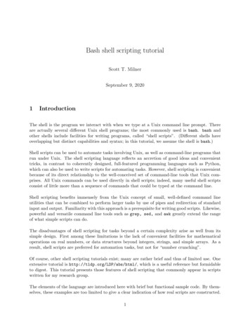
Introduction to Design of Shell StructuresGeneral Definition: A shell is a thin structure composed of curved sheets of material,so that the curvature plays an important role in the structuralbehavior, realizing a spatial form Motivation: A shell is the most efficient way of using the material, and can bevery useful in case o storage of fluids and solids (uniform loads)
Introduction to Design of Shell StructuresDifficulties The curved form may lead to different failure modes and oftenunexpected behavior occurs The analytical formulas are very complex and complicated incomparison with all the other structural forms Shell structures are very attractive light weight structures which areespecially suited to building as well as industrial applications.
Introduction to Design of Shell StructuresRange of application The shell structure is typically found in nature as well as in classical architecture. There are two principal uses of shells in civil engineering: industrial structures:– silos, tanks, cooling towers, reactor vessels etc. aesthetic and architectural special structures
Main documents Eurocode on strength and stability of Steel ShellStructures – EN1993 Part 1.6 (2007) Generic normative standard on shells forchimneys, towers, masts, silos, tanks, pipelines Buckling of Steel Shells European DesignRecommendations 5th Edition (ECCS – 2008)8
Introduction to Design of Shell StructuresGeneral Built structural shells
Introduction to Design of Shell StructuresGeneral Built structural shellsReinforced concreteSteelAluminium alloysPlasticsGlassTimber
Introduction to Design of Shell StructuresStructural typologiesEliptic paraboloidHyperbolic paraboloidCircular cylinder/cone
Introduction to Design of Shell StructuresStructural typologiesShells are the most difficult form of structure to analyse and the form withthe most complex behaviour. As a result, all but the simplest conditionsmust be analysed using computers.
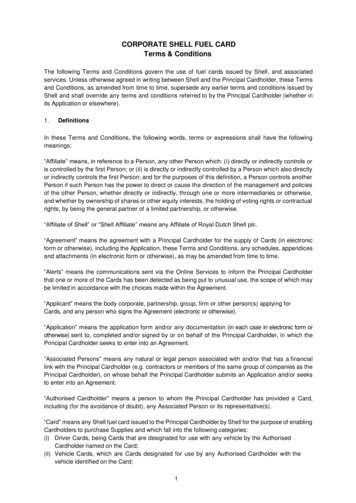
Introduction to Design of Shell StructuresExamples – Steel reticulated domeUS pavilion Expo 67 MontrealArchitect: Buckminster Fuller & Shoji SadaoThe 250ft diameter by 200ft high dome roughlypresents a three-quarter sphere, while geodesicdomes before 1967 were hemispherical. The domeconsists of steel pipes and 1,900 acrylic panels. Tokeep the indoor temperature acceptable, the designincluded mobile triangular panels that would moveover the inner surface following the sun. Althoughbrilliant on paper, this feature was too advanced forits time and never worked.
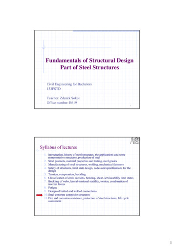
Introduction to Design of Shell StructuresExamples – Aluminium alloy reticulated domeSpruce Goose dome, Long Beach, USAArchitect: R. Duell and AssociatesEngineer/builder: TemcorA - Aluminum cover plate with silicone sealB - Aluminum gusset plates, bolted to strutsC - Aluminum batten secure silicone gasketsD - Triangular aluminum panelsE - Wide-flange aluminum strutsF - Stainless steel bolts
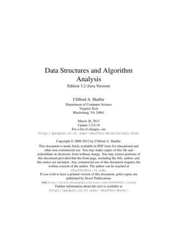
Introduction to Design of Shell StructuresExamples – Timber-steel free form grid shellMulti-hall, Mainz, GermanyArchitect: Mutschler, Frei Otto, consultantEngineer: Ove ArupThe multi-purpose dome for the 1975 gardenshow spans max. 60m with 50x50mm twinwood slats of 50cm squares that deformed intorhomboids.1 - Form-finding model2 - Interior3 - Mesh detail (steel bands resist shear)
Introduction to Design of Shell StructuresExamples – Timber-steel free form grid shellArchitect: Thomas HerzogEngineer: Julius NattererWood grid shell with PTFE membraneThe theme pavilion advanced the philosophy: Wood is the only renewable material Requires the least energy for production Use of wood maintains healthy forests
Introduction to Design of Shell StructuresShell lReticulated (bar structures) Continuous (or reticulated) shells Linear behaviourNon-linear behaviour Elastic Elastic-plasticBending stress stateMembrane stress state
Introduction to Design of Shell StructuresShell Design Resistance Stability Local bucklingof a tankHighly sensitive to imperfections Buckling is a process by which a structure cannot withstand loads with its originalshape, so that it changes this shape in order to find a new equilibriumconfiguration. This is an undesired process (from the point of view of theengineer), and occurs for a well–defined value of the load. The consequences of buckling are basically geometric: The are large displacements in the structure There may also be consequences for the material, in the sense thatdeflections may induce plasticity in the walls of the structureGlobal bucklingof a windturbine tower
Introduction to Design of Shell StructuresSteel Shell Design: CodificationConceptual designDesign for strength and bucklingDetailing
Introduction to Design of Shell StructuresBehavioural phenomenology of shells Behavior of a given structure (slender!) can be controlled by design ifthe three characteristic ranges of load-deformation curve are correctlydefined Pre-critical rangeCritical point (or range)Post-critical rangePPcrCritical pointPost-criticalrangePre-critical rangeP (0, Pcr] Structural stabilityP Pcr Structural instabilityDBuckling:elasticplasticdynamic
Introduction to Design of Shell StructuresBehavioural phenomenology of shells Instability phenomenon e.g. bifurcation instability of cylindersNN xsup,crN xinf,cr LL
Introduction to Design of Shell StructuresBehavioural phenomenology of shells Instability phenomenon – Jump of Equilibrium or Snap Through Instability Affects shallow arches and shells, reticulated shellsEREN Exhibition hall,Bucharest, 1963
Introduction to Design of Shell StructuresCritical and post-critical behaviour of elastic gth(unloaded)length(unloaded)Perfect barPwPerfectplatePuPPPPerfectbarPcrPPerfect platePerfect cylindricalshellPcrPcrAImperfectbarw0Imperfect plateImperfect cylindricalshellwColumnsindifferent post-critical pathw0wCylindersunstable post-critical pathw0wPlatesstable post-critical path
Introduction to Design of Shell StructuresFavourable and unfavourable effects of spatiality Curvature effect in axial compression cr , p 2E t 3 1 2 b cr ,c 2E t E b 2 2 3 1 b 4 r 22Stablecomponentincrease in critical load2Unstablecomponentincrease in sensitivity togeometrical imperfections
Introduction to Design of Shell StructuresFavourable and unfavourable effects of spatiality Curvature effect in axi-symetrical compressionincrease in critical loadincrease in sensitivity togeometrical imperfections
Introduction to Design of Shell StructuresCoupled instabilities for plate and shell elementsW – weak interactionM – moderate interactionS – strong interactionVS – very strong interaction
Introduction to Design of Shell StructuresCoupled instabilities for plate and shell elements Erosion of Theoretical Critical Buckling Load
Introduction to Design of Shell StructuresInstability phenomena: Influence of imperfections Agreement of theoretical and experimental valuesbarsshells
Introduction to Design of Shell StructuresInstability phenomena: basic types and models Dynamic propagation of instability or progressive instability Domino effect(double layer grids) Instability propagation(single layer reticulated shells)
Introduction to Design of Shell StructuresModels and Methods of Analysis Pre-Critical, Critical and Post-Critical Analysis Generic classification of structures in terms of characteristic instabilitytypes and sensitivity to imperfections Linear, nonlinear, elastic, plastic models Linear buckling analysis (eigen-buckling) – LBAGeometrical nonlinear imperfection analysis – GNIAGeometrical material nonlinear imperfection analysis – GMNIA Pre-critical solver methods (Newton – Raphson) or Post-critical solver methods (Arc-length); Designed load checking orload-deformation curve
Introduction to Design of Shell StructuresModels and Methods of Analysis Design flowchart for the Design of Shells according to EN 1993-1-6
Introduction to Design of Shell StructuresMethods of Analysis Methods of Analysis – Global Frame Analysis Finite Elements Methods for Analysis and DesignLoad-displacement curves found using differentanalyses of the same structure (Rotter, 2011)
Introduction to Design of Shell StructuresMethods of Analysis Basic modes for behavioura) Membraneb) Bending shellc) Shell like a membera)c)
Introduction to Design of Shell StructuresMethods of Analysis Basic Equations Simplified Linear Shell Theory The Love-Kirchhoff assumptions (simplified model) The shell thickness is negligibly small in comparison with the least radius ofcurvature of the shell middle surface (shell is thin) Strains and displacements that arise within the shell are small (products ofdeformations quantities that occur in the derivation of the theory may beneglected, ensuring that the system is described by a set of geometricallylinear equations) Straight lines that are normal to the middle surface prior to deformationremain straight and normal to the middle surface during deformation andexperience no change in length (analogue to hypothesis for beams – planesections before bending remain plane after bending) The direct stress actin in the direction normal to the shell middle surface isnegligible (not valid in the vicinity of concentrated transverse loads)
Introduction to Design of Shell StructuresMethods of Analysis Model of an axi-symmetrical Loaded ShellModel of an axisymetricallyloaded shellGeometrical parameter of thespherical shell
Introduction to Design of Shell StructuresMethods of Analysis General Rotation Shell Membrane Theory: Equilibrium Equations for Unsymmetrical Actions N N r0 r1 N r1 cos Yr1r0 0 N r0 N r1 N r1 cos Xr0r1 0 N r1 N z 0r2
Introduction to Design of Shell StructuresMethods of Analysis Cylindrical Shells Bending Theory Axisymmetric LoadingdN xa dx d 0dxdQxa dx d N dx d Z a dx d 0dxdM xa dx d Qx a dx d 0dxDd 4wdx4 Eha2w Z;D Eh3 12 1 3
Introduction to Design of Shell StructuresMethods of Analysis Shells aGeneral Bending Theory N x N x 0 x N a N x x Q 0 Q Qa x N q a 0 x a M x x M x a M aQ 0 M x aQx 0 xa N x N x 0 x N N a N x x 2 M x x a M x x 2M x x2 1 M 0a 2M x 21 M q a 0 x a 2
Introduction to Design of Shell StructuresMethods of Analysis Basic EquationsAspectEquationUnknown1. Equilibrium equations(static)582. Deformabilitycompatibility (geometric)9123. Physical aspect6---TOTAL2020
Introduction to Design of Shell StructuresMethods of Analysis Buckling of Cylindrical Shells in Compression General CaseEquilibrium equations for elastic buckling: N x N yz 0 x N y N x 2 v M xy M x a aN x 2 0 x x xa 222 2 M x M yx M y M xy 2waN x 2 N y a 0 x x 2 x a 2 x ax, ulz, w y, vwith solutions:2am xlm xv B cos n sinlm xw C sin n sinlu A sin n cosv 0n 0 u, w f x axial symetrical buckling
Introduction to Design of Shell StructuresMethods of Analysis Cylindrical Shells Membrane Theory Application for Wind Actionq 2N cos r0N 2q sin N qr0 cos
Introduction to Design of Shell StructuresMethods of Analysis Simplified Design Formulae (Cylindrical shells) r alTwo possible approaches Overall column buckling if l/r ratio is large Shell buckling which involves the cross section deformation and canbe, in general, either: Axisymmetric, when the displacement are constant aroundcircumferential section Asymmetric (chessboard shape), when waves are formed inboth axial circumferential directions
Introduction to Design of Shell StructuresMethods of Analysis Simplified Design Formulae Axial-symmetric buckling of cylindrical shell in compressionDd 4vdxD 4 Nx d 2wdxEh312 1 22 Ehwa2 0 Radial displacement:m xw A sinlNElastic critical axial stress ( cr cr )hEhm Eh cr 4 2;la Da 3 1 2 l 1.72 ahmIn case of axial-symmetrical buckling, the critical shear does not depend of cylinder length!If one of the cylinder ends is free (w 0), cr drops to 38% compared to simple supported case.Cylinder is highly sensitive to tangential displacements at the boundaries. If v 0, criticalstress drops to 50%!For 0.3
Introduction to Design of Shell StructuresMethods of Analysis Simplified Design Formulae Axial-symmetric buckling of cylindrical shell in compression Post-elastic critical buckling fyfpE tg 0Et tg 0 cr h EEt a 3 1 2 Etl 1.72 ahmE
Introduction to Design of Shell StructuresMethods of Analysis Simplified Design Formulae Axial-symmetric buckling of cylindrical shell in compressionPost-critical buckling: stable and unstable components m2 2NcrEl2 cr D 2 2 2 hl 2haDm 2 2 m 2 Eh h Ncr D l a2 m Stable componentUnstable component(inextensional bending(extensionally circumferentialdeformation – x direction)deformation – y direction
Introduction to Design of Shell StructuresMethods of Analysis Simplified Design Formulae Axial-symmetric buckling of cylindrical shell in compressionPost-critical buckling equationN1 1 m2Ncr8Stable component 2 3 Eh l 2 m8 Ncr a 2 m Unstable componentThe effect of circumferential extensional deformations increases the value ofcritical load, but change the type of instability from stable to unstable!
Introduction to Design of Shell StructuresMethods of Analysis Simplified Design Formulae Axial-symmetric buckling of cylindrical shell in compressionExamples: medium length cylinder (i,j) i no. of longitudinal half-length waves;j no. of circumferential half-length waves
Introduction to Design of Shell StructuresMethods of Analysis Simplified Design Formulae Axial-symmetric buckling of cylindrical shell in compressionExamples: long cylinder
Introduction to Design of Shell StructuresMethods of Analysis Simplified Design Formulae Axial-symmetric buckling of cylindrical shell in compressionExamples: short cylinder
Introduction to Design of Shell StructuresMethods of Analysis Simplified Design Formulae Axial-symmetric buckling of cylindrical shell in compressionPrinciple of ECCS approach (ECCS Recommendations 1998) Real cylinders are highly sensitive to imperfections “Knock-down” factor is introduced to account forimperfections and for plastic effects d cr depends on: Shell geometry Loading conditions Initial imperfections Material propertiesTest data and designcurve (typical) forcylinders subject toaxial compression
Introduction to Design of Shell StructuresMethods of Analysis Simplified Design Formulae Axial-symmetric buckling of cylindrical shell in compressionPrinciple of ECCS approachECCS design formulae forunstiffened cylinders For unstiffened cylinders,is similar to the one forcolumn in axial compression 2 cr 0.5 f y n 1 1 2 f y M1 2 cr 0.5 f y nfy 1 0.4123 1.2Graphical presentation ofECCS “knock-down” factor
Introduction to Design of Shell StructuresMethods of Analysis Simplified Design Formulae cr Buckling of cylindrical shells under external pressureMembrane (hoop) stress in practical rangeexternalpauniform y ; x 0hpressurepa y ; x 0.5 h Von Misses formula for critical pressure, cr Eh 1h2 22n 2 1 n 1 a n2 1 32 12a 2 3 n 1 ; 3 1 l 1 a “hydrostatic”type pressure2Simplified formulae for long cylinders2 Eh 1h2 2 2 1 1 pcr 2 2 n 3 1 2 2 2 a n 3 12a n min pcr 12a 1 Eh3 n 2 1 1pcr32
Introduction to Design of Shell StructuresMethods of Analysis Simplified Design Formulae Buckling of cylindrical shells under external pressurePrinciple of ECCS approach0 1 1pu1 py 1 2pu 2 ; 0.5py py p cr h Pcr E min a for l/a 0.5 min1.50.855 a h 1 2 l a ECCS design strength forunstiffened cylinderunder uniform pressure
Introduction to Design of Shell StructuresMethods of Analysis Simplified Design Formulae Buckling of cylindrical shells under external pressurePrinciple of ECCS approach Wind action is more complex than simply an external pressure It is needed to check the cylinder stability separately for: Wind radial pressure Wind axial effects Wind tangent effects Interaction of the three Approximately, wind critical pressure can be taken as 1.6 times criticalexternal pressure (Maderspach, Gaunt, Sword ) ECCS Design Recommendations (No. 125/2008) offers also a solution
Introduction to Design of Shell StructuresMethods of Analysis Simplified Design Formulae Buckling of cylindrical shells under compression and external pressure xp x ,cr pcrInteraction curve
Introduction to Design of Shell StructuresMethods of Analysis Simplified Design Formulae Buckling of cylindrical shells in bending (Flügge) cr , x M 1.33 cr , x Long cylinders (Brazier) M cr 0.99 1 2Eh 2aNx
Introduction to Design of Shell StructuresMethods of Analysis Simplified Design Formulae Buckling of cylindrical shells in torsion (Swerin and Flügge) long cylinders cr E3 2 1 2 h 34 a 32 (Donnel) short and medium long cylindrical shells Fixed end122 3 2 E h 2 l cr 4.6 7.8 1.671 2 l 2ah 1 Simple Supported End cr 12 3 2 2 h 2 l 2.8 2.6 1.41 l 2ah 2E 1 2
Introduction to Design of Shell StructuresMethods of Analysis Simplified Design Formulae Cylindrical shells under interactive buckling Bending external pressureBending torsion22 p Mp 1 1 or x cr cr x,cr M cr pcr 0.9 pcrCompression torsion x,cr crAxial compression externalpressure torsion2 p 1 x,cr pcr cr Axial compression bending torsion2 x x 1NM x,cr x,cr cr 2 1 External pressure torsionp pcr cr 2 1 2 1
Introduction to Design of Shell StructuresDesign of Steel Structures: Strength and Stability of Shells Basis of design and modelling Shells shall be designed in acc. with EN1990 and, in particular, to satisfy the followingrequirements: Overall equilibrium Equilibrium between actions and internal forces and moments Limitation of cracks due to cyclic plastification Limitation of cracks due to fatigue Types of analysis: Global analysis Membrane theory analysis Linear elastic shell analysis Linear elastic bifurcation analysis Geometrically nonlinear elastic analysis Materially nonlinear analysis Geometrically and materially nonlinear analysis Geometrically nonlinear elastic analysis with imperfections included Geometrically and materially nonlinear analysis with imperfections
Introduction to Design of Shell StructuresDesign of Steel Structures: Strength and Stability of Shells Basis of design and modelling Shells shall be designed in acc. with EN1990 and, in particular, to satisfy the followingrequirements: Overall equilibrium Equilibrium between actions and internal forces and moments Limitation of cracks due to cyclic plastification Limitation of cracks due to fatigue Types of analysis:approximate treatments of certain parts of Global analysisthe structure Membrane theory analysis Linear elastic shell analysis Linear elastic bifurcation analysis Geometrically nonlinear elastic analysis Materially nonlinear analysis Geometrically and materially nonlinear analysis Geometrically nonlinear elastic analysis with imperfections included Geometrically and materially nonlinear analysis with imperfections
Introduction to Design of Shell StructuresDesign of Steel Structures: Strength and Stability of Shells Basis of design and modelling Shells shall be designed in acc. with EN1990 and, in particular, to satisfy the followingrequirements: Overall equilibrium Equilibrium between actions and internal forces and moments Limitation of cracks due to cyclic plastification Limitation of cracks due to fatigue Conditions of use:Types of analysis:- the boundary conditions are appropriate for Global analysistransfer of the stresses in the shell into support Membrane theory analysisreactions without causing bending effects; Linear elastic shell analysis- the shell geometry varies smoothly in shape Linear elastic bifurcation analysis(without discontinuities); Geometrically nonlinear elastic analysis- the loads have a smooth distribution (without Materially nonlinear analysislocally concentrated or point loads). Geometrically and materially nonlinear analysis Geometrically nonlinear elastic analysis with imperfections included Geometrically and materially nonlinear analysis with imperfections
Introduction to Design of Shell StructuresDesign of Steel Structures: Strength and Stability of Shells Basis of design and modelling Shells shall be designed in acc. with EN1990 and, in particular, to satisfy the followingrequirements: Overall equilibrium Equilibrium between actions and internal forces and moments Limitation of cracks due to cyclic plastification Limitation of cracks due to fatigue Types of analysis: Global analysis-linear elastic material law Membrane theory analysis- linear small deflection theory (undeformed Linear elastic shell analysisgeometry) Linear elastic bifurcation analysis Geometrically nonlinear elastic analysis Materially nonlinear analysis Geometrically and materially nonlinear analysis Geometrically nonlinear elastic analysis with imperfections included Geometrically and materially nonlinear analysis with imperfections
Introduction to Design of Shell StructuresDesign of Steel Structures: Strength and Stability of Shells Basis of design and modelling Shells shall be designed in acc. with EN1990 and, in particular, to satisfy the followingrequirements: Overall equilibrium Equilibrium between actions and internal forces and moments Limitation of cracks due to cyclic plastification Limitation of cracks due to fatigue Types of analysis: Global analysisLBA Membrane theory analysis- linear elastic material law Linear elastic shell analysis- linear small deflection theory Linear elastic bifurcation analysis Geometrically nonlinear elastic analysis- imperfections of all kinds are ignored- the basis of the critical buckling resistance Materially nonlinear analysisevaluation Geometrically and materially nonlinear analysis Geometrically nonlinear elastic analysis with imperfections included Geometrically and materially nonlinear analysis with imperfections
Introduction to Design of Shell StructuresDesign of Steel Structures: Strength and Stability of Shells Basis of design and modelling Shells shall be designed in acc. with EN1990 and, in particular, to satisfy the followingrequirements: Overall equilibrium Equilibrium between actions and internal forces and moments Limitation of cracks due to cyclic plastification Limitation of cracks due to fatigue Types of analysis: Global analysis Membrane theory analysisGNA Linear elastic shell analysis-change in the geometry of the structure Linear elastic bifurcation analysis- the elastic buckling load of the perfect Geometrically nonlinear elastic analysis structure Materially nonlinear analysis Geometrically and materially nonlinear analysis Geometrically nonlinear elastic analysis with imperfections included Geometrically and materially nonlinear analysis with imperfections
Introduction to Design of Shell StructuresDesign of Steel Structures: Strength and Stability of Shells Basis of design and modelling Shells shall be designed in acc. with EN1990 and, in particular, to satisfy the followingrequirements: Overall equilibrium Equilibrium between actions and internal forces and moments Limitation of cracks due to cyclic plastification Limitation of cracks due to fatigue Types of analysis: Global analysis Membrane theory analysis Linear elastic shell analysisMNA Linear elastic bifurcation analysis Geometrically nonlinear elastic analysis- gives the plastic limit load and the plasticstrain increment Δε Materially nonlinear analysis Geometrically and materially nonlinear analysis Geometrically nonlinear elastic analysis with imperfections included Geometrically and materially nonlinear analysis with imperfections
Introduction to Design of Shell StructuresDesign of Steel Structures: Strength and Stability of Shells Basis of design and modelling Shells shall be designed in acc. with EN1990 and, in particular, to satisfy the followingrequirements: Overall equilibrium Equilibrium between actions and internal forces and moments Limitation of cracks due to cyclic plastification Limitation of cracks due to fatigue Types of analysis: Global analysis Membrane theory analysis Linear elastic shell analysis Linear elastic bifurcation analysis Geometrically nonlinear elastic analysisGMNA Materially nonlinear analysis- gives the geometrically nonlinear plastic limit Geometrically and materially nonlinearloadanalysisand the plastic strain increment Geometrically nonlinear elastic analysis with imperfections included Geometrically and materially nonlinear analysis with imperfections
Introduction to Design of Shell StructuresDesign of Steel Structures: Strength and Stability of Shells Basis of design and modelling Shells shall be designed in acc. with EN1990 and, in particular, to satisfy the followingrequirements: Overall equilibrium Equilibrium between actions and internal forces and moments Limitation of cracks due to cyclic plastification Limitation of cracks due to fatigue Types of analysis: Global analysis Membrane theory analysis Linear elastic shell analysis Linear elastic bifurcation analysis Geometrically nonlinear elastic analysis Materially nonlinear analysisGNIA Geometrically and materially nonlinearanalysis- wherecompression or shear stresses Geometrically nonlinear elastic analysiswith imperfectionsdominatein the shell included Geometrically and materially nonlinearanalysiswith imperfections- elasticbucklingloads of the "real" imperfectstructure
Introduction to Design of Shell StructuresDesign of Steel Structures: Strength and Stability of Shells Basis of design and modelling Shells shall be designed in acc. with EN1990 and, in particular, to satisfy the followingrequirements: Overall equilibrium Equilibrium between actions and internal forces and moments Limitation of cracks due to cyclic plastification Limitation of cracks due to fatigue Types of analysis: Global analysis Membrane theory analysis Linear elastic shell analysis Linear elastic bifurcation analysis Geometrically nonlinear elastic analysis Materially nonlinear analysis Geometrically and materially nonlinearGMNIAanalysisGNIA Geometrically nonlinear elastic analysis- kling loads for thewherecompressionor shear stresses Geometrically and materially nonlinear"real"analysiswithimperfectionsimperfect structuredominate in the shell- elastic buckling loads of the "real" imperfectstructure
Introduction to Design of Shell StructuresDesign of Steel Structures: Strength and Stability of Shells Basis of design and modelling Shells shall be designed in acc. with EN1990 and, in particular,to satisfythe followingMaterialShellType of analysisShell theorylawgeometryrequirements:membranenot OverallequilibriumMembranetheoryof shellsperfectequilibriumapplicable Equilibrium between actions and internal forces and momentsLinear elastic shelllinear bendinglinearperfect Limitationofcracksduetocyclicanalysis (LA)and plastificationstretching Limitationof cracks due to fatigueLinearelastic bifurcationlinear bendinglinearperfectanalysis (LBA)and stretchingnon-linear GeometricallyTypes of nts ofcertain parts ofelasticanalysis(GNA) Globalanalysisthe structureConditionsof use:non-linear MateriallyMembranetheory analysislinearnon-linearperfect--linearthe boundaryconditionsare appropriate foranalysis (MNA)elasticmateriallaw Linear elastic shell analysisGeometrically and materiallytransferof thedeflectionstresses in theorythe shell(undeformedinto support- linearLBA smallnon-linearnon-linearperfect Linearelasticbifurcationanalysisnon-linear analysis (GMNA)reactionswithoutcausinglawbending effects;- linear elasticmaterialgeometry)GNA GeometricallynonlinearelasticanalysisGeometrically non-linear-MNAtheshellgeometryvariessmoothlyin shape- he structure elasticMateriallynonlinearanalysiswith analysis non-linearlinearimperfectdiscontinuities);- climitloadplasticimperfections(GNIA) Geometrically and materially nonlinearGMNIAanalysis- theloadshavea inincrementΔε Geometrically nonlinear elastic analysislocallywithconcentratedimperfectionsor klingloadsfortheevaluationandcompressiontheplastic strainincrementnon-linear analysis withnon-linearnon-linearimperfect- whereor shearstresses Geometrically and materially nonlinearanalysiswithimperfections"real" imperfect structureimperfections (GMNIA)d
The shell structure is typically found in nature as well as in classical architecture. There are two principal uses of shells in civil engineering: industrial structures: - silos, tanks, cooling towers, reactor vessels etc. aesthetic and architectural special structures Introduction to Design of Shell Structures Range of application Eurocode on strength and .