Transcription
NEHRP RECOMMENDED PROVISIONSSEISMIC DESIGN OF STEEL STRUCTURES Context in NEHRP Recommended Provisions Steel behavior Reference standards and design strength Moment resisting frames Braced frames Other topics SummaryInstructional Material Complementing FEMA 451, Design ExamplesSteel Structures 10 - 1
Steel Design: Context in ProvisionsDesign basis: Strength limit stateUsing the 2003 NEHRP Recommended Provisions:Load combinationChap. 4Seismic load analysisChap. 5Components and attachments Chap. 6Design of steel structuresChap. 8AISC Seismicand othersInstructional Material Complementing FEMA 451, Design ExamplesSteel Structures 10 - 2
Seismic Resisting SystemsUnbraced Frames Joints are:Rigid/FR/PR/Moment-resisting Seismic classes are:Special/intermediate/Ordinary/not detailedBraced Frames Concentric bracing Eccentric bracingInstructional Material Complementing FEMA 451, Design ExamplesSteel Structures 10 - 3
Monotonic Stress-Strain BehaviorInstructional Material Complementing FEMA 451, Design ExamplesSteel Structures 10 - 4
Bending of Steel BeamStrainMStressφyExtreme fiber reachesyield strain and stressεyσyStrain slightly above yield strainεy ε εsh σySection near “plastic”φuεshInstructional Material Complementing FEMA 451, Design ExamplesσySteel Structures 10 - 5
Plastic Hinge FormationInstructional Material Complementing FEMA 451, Design ExamplesSteel Structures 10 - 6
Cross - section DuctilityConceptual moment - curvatureMMpMyφu φu ε u φy′ φy ε yφ y φ′yInstructional Material Complementing FEMA 451, Design ExamplesφφuSteel Structures 10 - 7
Moment CurvatureLaboratory Test -- Annealed W BeamInstructional Material Complementing FEMA 451, Design ExamplesSteel Structures 10 - 8
Behavior Modes For BeamsMrOLMOHIOJGOJEOJKElastic lateral tors. bucklingInelastic lateral tors. bucklingInelastic lateral tors. bucklingIdealized behaviorStrain hardeningInstructional Material Complementing FEMA 451, Design ExamplesSteel Structures 10 - 9
Flexural Ductility of Steel MembersPractical Limits123Lateral torsional bucklingBrace wellLocal bucklingLimit width-to-thickness ratiosfor compression elementsFractureAvoid by proper detailingInstructional Material Complementing FEMA 451, Design ExamplesSteel Structures 10 - 10
Local and Lateral BucklingInstructional Material Complementing FEMA 451, Design ExamplesSteel Structures 10 - 11
Lateral Torsional BucklingInstructional Material Complementing FEMA 451, Design ExamplesSteel Structures 10 - 12
Local BucklingbtClassical plate buckling solution:σ cr kπ 2 E12(1 μ )(b / t )22 σySubstituting μ 0.3 and rearranging:bkE 0.95tFyInstructional Material Complementing FEMA 451, Design ExamplesSteel Structures 10 - 13
Local BucklingcontinuedWith the plate buckling coefficient taken as 0.7 and an adjustmentfor residual stresses, the expression for b/t becomes:bE 0.38tFyThis is the slenderness requirement given in the AISC specificationfor compact flanges of I-shaped sections in bending. Thecoefficient is further reduced for sections to be used in seismicapplications in the AISC Seismic specificationbE 0.3tFyInstructional Material Complementing FEMA 451, Design ExamplesSteel Structures 10 - 14
Welded Beam to Column Laboratory Test - 1960sInstructional Material Complementing FEMA 451, Design ExamplesSteel Structures 10 - 15
Bolted Beam to Column Laboratory Test - 1960sInstructional Material Complementing FEMA 451, Design ExamplesSteel Structures 10 - 16
Pre-Northridge StandardInstructional Material Complementing FEMA 451, Design ExamplesSteel Structures 10 - 17
Following the 1994Northridge earthquake,numerous failures of steelbeam-to-column momentconnections were identified.This led to a multiyear,multimillion dollar FEMAfunded research effortknown as the SAC jointventure. The failures causeda fundamental rethinking ofthe design of seismicresistant steel momentconnections.Instructional Material Complementing FEMA 451, Design ExamplesSteel Structures 10 - 18
Bottom Flange Weld Fracture Propagating Through ColumnFlange and WebInstructional Material Complementing FEMA 451, Design ExamplesSteel Structures 10 - 19
Beam Bottom Flange Weld Fracture Causing a Column DivotFractureInstructional Material Complementing FEMA 451, Design ExamplesSteel Structures 10 - 20
Northridge FailureBeamweb Crack through weld Note backup barand runoff tabInstructional Material Complementing FEMA 451, Design ExamplesBottom flangeof beamSteel Structures 10 - 21
Northridge FailureBeam flangeand webColumnflangeBackup barInstructional Material Complementing FEMA 451, Design ExamplesSteel Structures 10 - 22
Northridge FailuresWeldWeld FusionColumn FlangeHAZInstructional Material Complementing FEMA 451, Design ExamplesColumn DivotLamellar TearSteel Structures 10 - 23
Flexural Mechanics at a Joint221121Cross SectionsFw12FyFyBeam MomentFwFw Z1 Fy Z2Instructional Material Complementing FEMA 451, Design ExamplesSteel Structures 10 - 24
Welded Steel Frames Northridge showed serious flaws. Problemscorrelated with:- Weld material, detail concept and workmanship- Beam yield strength and size- Panel zone yield Repairs and new design- Move yield away from column face(cover plates, haunches, “dog bone”)- Verify through tests SAC Project: FEMA Publications 350 through 354Instructional Material Complementing FEMA 451, Design ExamplesSteel Structures 10 - 25
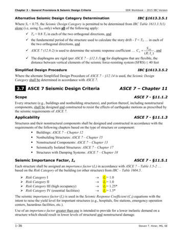
Moment (MN-m)Reduced Beam Section (RBS) Test SpecimenSAC Joint Venture420-2-4-4-2024Plastic Rotation (% rad)Graphics courtesy of Professor Chia-Ming Uang, University of California San DiegoInstructional Material Complementing FEMA 451, Design ExamplesSteel Structures 10 - 26
T-stub Beam-Column TestSAC Joint VenturePhoto courtesy of Professor Roberto Leon, Georgia Institute of TechnologyInstructional Material Complementing FEMA 451, Design ExamplesSteel Structures 10 - 27
T-Stub Failure MechanismsPlastic hinge formation -- flange andweb local bucklingNet section fracture in stem of T-stubPhotos courtesy of Professor Roberto Leon, Georgia Institute of TechnologyInstructional Material Complementing FEMA 451, Design ExamplesSteel Structures 10 - 28
T-Stub Connection Moment Rotation t (kN-m)Moment (k-in)FS-03 - Moment/Rotation0.06Rotation (rad)Graphic courtesy of Professor Roberto Leon, Georgia Institute of TechnologyInstructional Material Complementing FEMA 451, Design ExamplesSteel Structures 10 - 29
Extended Moment End-Plate Connection ResultsPhoto courtesy of Professor Thomas Murray, Virginia TechInstructional Material Complementing FEMA 451, Design ExamplesSteel Structures 10 - 30
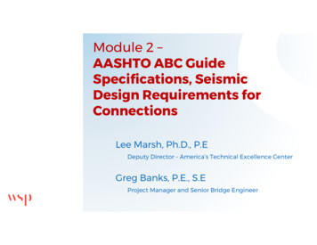
25000250002000020000Moment at Column Centerline (in-kips)Moment at Column Centerline (in-kips)Extended Moment End-Plate Connection -0.08-0.06-0.04-0.020.000.020.04Total Rotation (rad)(a) Moment vs Total 8Total Plastic Rotation (rad)(b) Moment vs Plastic RotationGraphics courtesy of Professor Thomas Murray, Virginia TechInstructional Material Complementing FEMA 451, Design ExamplesSteel Structures 10 - 31
Ductility of Steel Frame JointsLimitsWelded Joints- Brittle fracture of weld- Lamellar tearing of base metal- Joint design, testing, and inspectionBolted Joints- Fracture at net cross-section- Excessive slipJoint Too Weak For Member- Shear in joint panelInstructional Material Complementing FEMA 451, Design ExamplesSteel Structures 10 - 32
Multistory FrameLaboratory TestInstructional Material Complementing FEMA 451, Design ExamplesSteel Structures 10 - 33
Flexural DuctilityEffect of Axial Loade P 0PyM pcMpL 7.0rx 1 .0W12x36e 5.10"P 0.55PyMpce 1.75"P 0.76PyMpcMpMp 0.57 0.28Instructional Material Complementing FEMA 451, Design ExamplesSteel Structures 10 - 34
Axial StrutLaboratory testL 45rInstructional Material Complementing FEMA 451, Design ExamplesSteel Structures 10 - 35
Cross Braced FrameLaboratory testInstructional Material Complementing FEMA 451, Design ExamplesSteel Structures 10 - 36
Tension Rod (Counter) BracingConceptual BehaviorHHΔ“Slapback”For cycle 2Instructional Material Complementing FEMA 451, Design ExamplesSteel Structures 10 - 37
Eccentrically Braced FrameInstructional Material Complementing FEMA 451, Design ExamplesSteel Structures 10 - 38
Eccentrically Braced FrameLab test of linkInstructional Material Complementing FEMA 451, Design ExamplesSteel Structures 10 - 39
Steel Behavior Ductility- Material inherently ductile- Ductility of structure ductility of material Damping- Welded structures have low damping- More damping in bolted structures dueto slip at connections- Primary energy absorption is yielding ofmembersInstructional Material Complementing FEMA 451, Design ExamplesSteel Structures 10 - 40
Steel Behavior Buckling- Most common steel failure under earthquake loads- Usually not ductile- Local buckling of portion of member- Global buckling of member- Global buckling of structure Fracture- Nonductile failure mode under earthquake loads- Heavy welded connections susceptibleInstructional Material Complementing FEMA 451, Design ExamplesSteel Structures 10 - 41
NEHRP Recommended ProvisionsSteel Design Context in NEHRP Recommended Provisions Steel behavior Reference standards and design strengthInstructional Material Complementing FEMA 451, Design ExamplesSteel Structures 10 - 42
Instructional Material Complementing FEMA 451, Design ExamplesSteel Structures 10 - 43
Using Reference StandardsStructural SteelBoth the AISC LRFD and ASD methodologies arepresented in a unified format in both theSpecification for Structural Steel Buildings and theSeismic Provisions for Structural Steel Buildings.Instructional Material Complementing FEMA 451, Design ExamplesSteel Structures 10 - 44
Instructional Material Complementing FEMA 451, Design ExamplesSteel Structures 10 - 45
Other Steel MembersSteel Joist InstituteStandard Specifications, 2002Steel CablesASCE 19-1996Steel Deck InstituteDiaphragm Design Manual, 3rd Ed., 2005Instructional Material Complementing FEMA 451, Design ExamplesSteel Structures 10 - 46
NEHRP Recommended ProvisionsSteel Design Context in NEHRP Recommended Provisions Steel behavior Reference standards and design strength Moment resisting framesInstructional Material Complementing FEMA 451, Design ExamplesSteel Structures 10 - 47
Steel Moment Frame structional Material Complementing FEMA 451, Design ExamplesSteel Structures 10 - 48
Steel Moment Frame Jointsa bMu M p bFy* Ry Fya b 1 1.7 Fy*Fu F Z bAf d*yInstructional Material Complementing FEMA 451, Design ExamplesSteel Structures 10 - 49
Panel ZonesSpecial and intermediate momentframe: Shear strength demand:Basic load combinationφRyMp of beamsor Shear capacity equation Thickness (for buckling) Use of doubler platesInstructional Material Complementing FEMA 451, Design ExamplesSteel Structures 10 - 50
Steel Moment Frames Beam shear: 1.1RyMp gravity Beam local buckling- Smaller b/t than LRFD for plastic design Continuity plates in joint per tests Strong column - weak beam rule- Prevent column yield except in panel zone- Exceptions: Low axial load, strong stories, topstory,and non-SRS columnsInstructional Material Complementing FEMA 451, Design ExamplesSteel Structures 10 - 51
Steel Moment Frames Lateral support of column flange- Top of beam if column elastic- Top and bottom of beam otherwise- Amplified forces for unrestrained Lateral support of beams- Both flanges- Spacing 0.086ryE/FyInstructional Material Complementing FEMA 451, Design ExamplesSteel Structures 10 - 52
Prequalified ConnectionsSee FEMA 350: Recommended Seismic Design Criteria forNew Steel Moment-Frame Buildings-Welded Unreinforced Flange-Welded Free Flange Connection-Welded Flange Plate Connection-Reduced Beam Section Connections-Bolted Unstiffened End Plate Connection-Bolted Stiffened End Plate Connection-Bolted Flange Plate ConnectionSee ANSI/AISC 358-05, Prequalified Connections for Special andIntermediate Steel Moment Frames for Seismic Applications-Reduced Beam Section Connections-Bolted Stiffened and Unstiffened Extended Moment End Plate ConnectionsInstructional Material Complementing FEMA 451, Design ExamplesSteel Structures 10 - 53
Welded CoverplatesInstructional Material Complementing FEMA 451, Design ExamplesSteel Structures 10 - 54
Reduced Beam Section (RBS)Instructional Material Complementing FEMA 451, Design ExamplesSteel Structures 10 - 55
Extended End PlateInstructional Material Complementing FEMA 451, Design ExamplesSteel Structures 10 - 56
Excellent Moment Frame BehaviorInstructional Material Complementing FEMA 451, Design ExamplesSteel Structures 10 - 57
Excellent Moment Frame BehaviorInstructional Material Complementing FEMA 451, Design ExamplesSteel Structures 10 - 58
Excellent Moment Frame BehaviorInstructional Material Complementing FEMA 451, Design ExamplesSteel Structures 10 - 59
Special Moment FramesExample5 at 25'-0"7 at 25'-0"NInstructional Material Complementing FEMA 451, Design ExamplesSteel Structures 10 - 60
Special Moment FramesThe following design steps will be reviewed: Select preliminary member sizes Check member local stability Check deflection and drift Check torsional amplification Check the column-beam moment ratio rule Check shear requirement at panel zone Select connection configurationInstructional Material Complementing FEMA 451, Design ExamplesSteel Structures 10 - 61
Special Moment FramesSelect preliminary member sizes – The preliminarymember sizes are given in the next slide for theframe in the East-West direction. These memberswere selected based on the use of a 3D stiffnessmodel in the program RAMFRAME. As will bediscussed in a subsequent slide, the driftrequirements controlled the design of thesemembers.Instructional Material Complementing FEMA 451, Design ExamplesSteel Structures 10 - 62
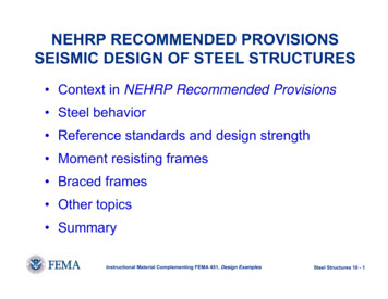
SMF Example – Preliminary Member SizesInstructional Material Complementing FEMA 451, Design ExamplesSteel Structures 10 - 63
SMF Example – Check Member Local StabilityCheck beam flange:(W33x141 A992)bf 6.012tfbftfE 7.22OKUpper limit: 0.3FyhcCheck beam web: 49.6twEUpper limit: 3.76 90.6FyhctwOKInstructional Material Complementing FEMA 451, Design ExamplesSteel Structures 10 - 64
SMF Example – Check Deflection and DriftThe frame was checked for an allowable story drift limit of0.020hsx. All stories in the building met the limit. Note that theNEHRP Recommended Provisions Sec. 4.3.2.3 requires thefollowing check for vertical irregularity:Cd Δ xstory 2Cd Δ xstory 3 5.17in. 268in. 0.98 1.3 3.14in. 160in. Therefore, there is no vertical irregularity.Instructional Material Complementing FEMA 451, Design ExamplesSteel Structures 10 - 65
SMF Example – Check Torsional AmplificationThe torsional amplification factor is given below. If Ax 1.0then torsional amplification is not required. From theexpression it is apparent that if δmax / δavg is less than 1.2,then torsional amplification will not be required. δ maxAx 1.2δavg 2The 3D analysis results, as shown in FEMA 451, indicatethat none of the δmax / δavg ratios exceed 1.2; therefore,there is no torsional amplification.Instructional Material Complementing FEMA 451, Design ExamplesSteel Structures 10 - 66
SMF Example – Member Design NEHRP GuideMember Design Considerations - Because Pu/φPn istypically less than 0.4 for the columns, combinationsinvolving Ω0 factors do not come into play for thespecial steel moment frames (re: AISC SeismicSec. 8.3). In sizing columns (and beams) forstrength one should satisfy the most severe valuefrom interaction equations. However, the frame inthis example is controlled by drift. So, with bothstrength and drift requirements satisfied, we willcheck the column-beam moment ratio and thepanel zone shear.Instructional Material Complementing FEMA 451, Design ExamplesSteel Structures 10 - 67
SMF Example – Column-Beam Moment RatioPer AISC Seismic Sec. 9.6*Σ M pcΣM*pb 1.0where ΣM*pc the sum of the moments in the column above andbelow the joint at the intersection of the beam and columncenterlines. ΣM*pc is determined by summing the projections of thenominal flexural strengths of the columns above and below thejoint to the beam centerline with a reduction for the axial force inthe column.ΣM*pb the sum of the moments in the beams at the intersection ofthe beam and column centerlines.Instructional Material Complementing FEMA 451, Design ExamplesSteel Structures 10 - 68
SMF Example – Column-Beam Moment RatioColumn – W14x370; beam – W33x141ΣM*pc*ΣM pc Puc 500kips 2 273650 ΣZc Fyc inksi 2 109Ain g 66,850in kipsAdjust this by the ratio of average story height to average clearheight between beams.268in. 160in. *ΣM pc 66,850in kips 75,300in kips 251.35in. 128.44in. Instructional Material Complementing FEMA 451, Design ExamplesSteel Structures 10 - 69
SMF Example – Column-Beam Moment RatioFor beams:*ΣM pb Σ(1.1Ry M p Mv )with Mv VpShS h dist . from col . centerline to plastic hinge dc / 2 d b / 2 25.61in.Vp shear at plastic hinge locationwL' 22M p '22Vp 2M p wL / 2 ' L (1.046klf ) ( 248.8in.)2 ( 2 )( 25,700in kips ) 122 221.2kips 248.8in.()Instructional Material Complementing FEMA 451, Design ExamplesSteel Structures 10 - 70
SMF Example – Column-Beam Moment RatioMv VpSh (221.2kips )(25.61in.) 5,665in kipsand*ΣM pb Σ(1.1Ry M p Mv ) 2[(1.1)(1.1)(25,700in kips ) 5,665in kips ] 73,500in kipsThe ratio of column moment strengths to beam moment strengths iscomputed as:Ratio *ΣM pc*ΣM pb 75,300in kips 1.02 1.00 OK73,500in kipsOther ratios are also computed to be greater than 1.0Instructional Material Complementing FEMA 451, Design ExamplesSteel Structures 10 - 71
SMF Example –Panel Zone CheckThe 2005 AISC Seismic specification is used to check the panel zone strength. Notethat FEMA 350 contains a different methodology, but only the most recent AISCprovisions will be used. From analysis shown in the NEHRP Design Examples volume(FEMA 451), the factored strength that the panel zone at Story 2 of the frame in theEW direction must resist is 1,883 kips. 3bcf tcf2 (3)(16.475in.)(2.66)2 Rv 0.6Fy dc t p 1 (0.6)(50ksi )(17.92in.)(t p ) 1 ddt(33.3in.)(17.92in.)(t) b c p p Rv 537.6t p 315The required total (web plus doubler plate ) thickness is determined by :φ Rv Ru(1.0)(537.6t p 315) 1,883kipst prequired 2.91in.The column web thickness is 1.66in., therefore the required doubler plate thickness is :t pdoubler 1.25in. (therefore use one 1.25in. plate or two 0.625in. plates )Instructional Material Complementing FEMA 451, Design ExamplesSteel Structures 10 - 72
SMF Example – Connection ConfigurationInstructional Material Complementing FEMA 451, Design ExamplesSteel Structures 10 - 73
SMF Example – Connection ConfigurationInstructional Material Complementing FEMA 451, Design ExamplesSteel Structures 10 - 74
Special Moment FramesSummaryBeam to column connection capacitySelect preliminary member sizesCheck member local stabilityCheck deflection and driftCheck torsional amplificationCheck the column-beam moment ratio ruleCheck shear requirement at panel zoneSelect connection configuration Prequalified connections TestingInstructional Material Complementing FEMA 451, Design ExamplesSteel Structures 10 - 75
NEHRP Recommended ProvisionsSteel Design Context in ProvisionsSteel behaviorReference standards and design strengthSeismic design category requirementMoment resisting framesBraced framesInstructional Material Complementing FEMA 451, Design ExamplesSteel Structures 10 - 76
Concentrically Braced FramesBasic ConfigurationsXInverted VDiagonalKVKInstructional Material Complementing FEMA 451, Design ExamplesSteel Structures 10 - 77
Braced Frame UnderConstructionInstructional Material Complementing FEMA 451, Design ExamplesSteel Structures 10 - 78
Braced Frame Under ConstructionInstructional Material Complementing FEMA 451, Design ExamplesSteel Structures 10 - 79
Concentrically Braced FramesSpecial AISC SeismicR 6Chapter 13Ordinary AISC SeismicR 3.25Chapter 14Not Detailed for SeismicR 3AISC LRFDInstructional Material Complementing FEMA 451, Design ExamplesSteel Structures 10 - 80
Concentrically Braced FramesDissipate energy after onset of global buckling byavoiding brittle failures: Minimize local buckling Strong and tough end connections Better coupling of built-up membersInstructional Material Complementing FEMA 451, Design ExamplesSteel Structures 10 - 81
Concentrically Braced FramesSpecial and OrdinaryBracing members:- Compression capacity φcPn- Width / thickness limitsGenerally compactAngles, tubes and pipes very compact- OverallKL 4rEFy- Balanced tension and compressionInstructional Material Complementing FEMA 451, Design ExamplesSteel Structures 10 - 82
Concentrically Braced FramesSpecial concentrically braced framesBrace connectionsAxial tensile strength smallest of: Axial tension strength RyFyAg Maximum load effect that can be transmitted tobrace by system.Axial compressive strength 1.1RyPn where Pn is thenominal compressive strength of the brace.Flexural strength 1.1RyMp or rotate to permitbrace buckling while resisting AgFCRInstructional Material Complementing FEMA 451, Design ExamplesSteel Structures 10 - 83
Concentrically Braced FramesV bracing: Design beam for D L unbalanced brace forces,using 0.3φPc for compression and RyFyAg in tension Laterally brace the beam Beams between columns shall be continuous.K bracing: Not permittedInstructional Material Complementing FEMA 451, Design ExamplesSteel Structures 10 - 84
Concentrically Braced FramesBuilt-up member stitches: Spacing 40% KL/r No bolts in middle quarter of span Minimum strengths related to PyColumn in CBF: Same local buckling rules as brace members Splices resist momentsInstructional Material Complementing FEMA 451, Design ExamplesSteel Structures 10 - 85
ConcentricallyBraced FrameExampleE-W directionInstructional Material Complementing FEMA 451, Design ExamplesSteel Structures 10 - 86
Concentrically Braced Frame ExampleThe following general design steps are required: Selection of preliminary member sizes Check strength Check drift Check torsional amplification Connection designInstructional Material Complementing FEMA 451, Design ExamplesSteel Structures 10 - 87
Eccentrically Braced FramesLinkBraceBeamInstructional Material Complementing FEMA 451, Design ExamplesSteel Structures 10 - 88
Eccentrically Braced Frame Under ConstructionInstructional Material Complementing FEMA 451, Design ExamplesSteel Structures 10 - 89
Eccentrically Braced Frame Under ConstructionInstructional Material Complementing FEMA 451, Design ExamplesSteel Structures 10 - 90
Eccentrically Braced FramesEccentric bracing systemsRCd8474Building frame system or part ofdual system w/ special moment frameWith moment resisting connectionsat columns away from linksWithout moment resisting connectionsat columns away from linksThese connectionsdetermine classificationInstructional Material Complementing FEMA 451, Design ExamplesSteel Structures 10 - 91
Eccentrically Braced FramesDesign Procedure1.2.3.4.Elastic analysisCheck rotation angle; reproportion as requiredDesign check for strengthDesign connection detailsInstructional Material Complementing FEMA 451, Design ExamplesSteel Structures 10 - 92
Eccentrically Braced FramesExampleInstructional Material Complementing FEMA 451, Design ExamplesSteel Structures 10 - 93
Eccentrically Braced FramesRotation Angle1. Compute total Δ Cd ΔE2. Deform model as rigidplastic mechanism withhinges at ends of line3. Compute rotation angleat end of linkα 0.08 radians when L 1.6 M pα 0.02 radians when L 2.6 M pInterpolate for α whenVpVp1.6 M pVp L 2.6 M pVp4. Check limits (Sec. 15.2g)Instructional Material Complementing FEMA 451, Design ExamplesSteel Structures 10 - 94
Eccentrically Braced FramesRotation Angle ExampleFrom computer analysis:ΔΔ e 0.247 in8.5'Total drift:θFrom geometry: L 20 0.99 α θ 0.043 e 3 12.67 (12 ) 1.6M p 3.52'Because e 3.0 ' Fyα max 0.08 rad 0.043 rad8.5'α12.67'Δ Cd Δ e 4(0.247) 0.99 in.3.0'radOKInstructional Material Complementing FEMA 451, Design ExamplesSteel Structures 10 - 95
Eccentrically Braced FramesRotation Angle Rotation angle limits based on link beam equivalentlength- Short links yield in shear and are allowedgreater rotation Rotation angle may be reduced in design by:- Increasing member size (reducing Δe)- Changing geometric configuration(especially changing length of link beam)Instructional Material Complementing FEMA 451, Design ExamplesSteel Structures 10 - 96
Eccentrically Braced FramesLink Design Provide strength V and M per load combinations Check lateral bracing per AISC Lpd Local buckling (width to thickness of web andflange) per AISC Seismic Stiffeners (end and intermediate) perAISC SeismicInstructional Material Complementing FEMA 451, Design ExamplesSteel Structures 10 - 97
Eccentrically Braced FramesBrace DesignStrength 1.25 R y axial force from design shear strength of link Instructional Material Complementing FEMA 451, Design ExamplesSteel Structures 10 - 98
Eccentrically Braced FramesBrace Design ExampleCheck axial strength of 15.26 ft long TS 8 x 8 x 5/8 Fy 46 ksi:KL (1)(15.26) (12 ) 61.2r2.99E61.2 4.71 118.3FyFe π 2E2 π 2 (29,000)2Fy Fcr 0.658 Fe Fy 76.4 ksi61.2 KL r 46 76.4Fcr 0.658 46 35.8ksi φc Pn φc Ag Fcr 0.9 (16.4 )( 35.8 ) 528 kipInstructional Material Complementing FEMA 451, Design ExamplesSteel Structures 10 - 99
Eccentrically Braced FramesBrace Design ExampleφVn 0.9(0.6Fy )d tw 0.9 0.6 ( 50 )(16.4 )( 0.43 ) 190 kiporφVn 2(0.9)M / e 2 ( 0.9 )( 50 )(105 )pVe ( link ) 85.2 kipand3 (12 ) 262.5 kipPe ( brace ) 120.2 kip 190 Pu 1.25 (1.1) (120.2 ) 369 528 OK 85.2 Instructional Material Complementing FEMA 451, Design ExamplesSteel Structures 10 - 100
NEHRP Recommended ProvisionsSteel Design Context in NEHRP Recommended Provisions Steel behavior Reference standards and design strength Moment resisting frames Braced frames Other topicsInstructional Material Complementing FEMA 451, Design ExamplesSteel Structures 10 - 101
Special Truss Moment Frame Buckling and yieldingin special section Design to be elasticoutside special section Deforms similar to EBF Special panels to besymmetric X orVierendeelInstructional Material Complementing FEMA 451, Design ExamplesSteel Structures 10 - 102
Special Truss Moment FrameGeometric Limits:L 65'0.1 d 6'Ls 0.5LL23 p 3d2Flat bar diagonals,Instructional Material Complementing FEMA 451, Design Examplesb 2.5tSteel Structures 10 - 103
Special Truss Moment Frame 2 M pcVp 2 Ls sin α ( Pnt 0.3Pcd ) F h VLiipInstructional Material Complementing FEMA 451, Design ExamplesSteel Structures 10 - 104
Special Truss Moment FrameInstructional Material Complementing FEMA 451, Design ExamplesSteel Structures 10 - 105
Special Truss Moment FrameInstructional Material Complementing FEMA 451, Design ExamplesSteel Structures 10 - 106
General Seismic DetailingMaterials: Limit to lower strengths and higher ductilitiesBolted Joints: Fully tensioned high strength bolts Limit on bearingInstructional Material Complementing FEMA 451, Design ExamplesSteel Structures 10 - 107
General Seismic DetailingWelded Joints: AWS requirements for welding procedure specs Filler metal toughness CVN 20 ft-lb @ -20 F, or AISC Seismic App. X Warning on discontinuities, tack welds, run offs,gouges, etc.Columns: Strength using Ωo if Pu /φPn 0.4 Splices: Requirements on partial pen welds andfillet weldsInstructional Material Complementing FEMA 451, Design ExamplesSteel Structures 10 - 108
Steel DiaphragmExampleφVn φ (approved strength)φ 0.6For example only:Use approved strength as 2.0 x working load inSDI Diaphragm Design ManualInstructional Material Complementing FEMA 451, Design ExamplesSteel Structures 10 - 109
Steel Deck Diaphragm ExampleLVEVEwEdL 80'd 40'wD wL 0wE 500 plfVE v SDIwEL 20 kip;2vE 20000 500 plf40vE500 417 plf2φ 2(0.6 )Deck chosen:1½ “, 22 gage with welds on 36/5 pattern and 3sidelap fasteners, spanning 5’-0”Capacity 450 417 plfInstructional Material Complementing FEMA 451, Design ExamplesSteel Structures 10 - 110
Welded Shear StudsInstructional Material Complementing FEMA 451, Design ExamplesSteel Structures 10 - 111
Shear Stud Strength - AISC 2005 SpecificationQn 0.5 Asc ( fc’ Ec)1/2 Rg Rp Asc FuRg stud geometry adjustment factorRp stud position adjustment factorNote that the strength reduction factor for bending hasbeen increased from 0.85 to 0.9. This results from thestrength model for shear studs being more accurate,although the result for Qn is lower in the 2005specification.Instructional Material Complementing FEMA 451, Design ExamplesSteel Structures 10 - 112
Shear Studs – Group Adjustment FactorQn 0.5 Asc ( fc’ Ec)1/2 Rg Rp Asc FuRg stud group adjustment factorRg 1.0Rg 1.0*Rg 0.85Rg 0.7*0.85 if wr/hr 1.5Instructional Materi
Instructional Material Complementing FEMA 451, Design Examples Steel Structures 10 - 2 Steel Design: Context in Provisions Design basis: Strength limit state Using the 2003 NEHRP Recommended Provisions: Load combination Chap. 4 Seismic load analysis Chap. 5 Components and attachments Chap. 6 Design of