Transcription
BracingFixing ManualHardiBraceTM Sheet BracingHardiFlexTM SheetsHardPlankTM WeatherboardsHardiTexTM Base SheetsPanelCladTM SheetsPineRidgeTM LiningPrimeLineTM WeatherboardsVersiluxTM LiningVillaboardTM LiningFor Use in Australia Only
James Hardie products and their applications* 6mm sheet onlyInformation on James Hardie fibre cement products and systemsand their applications, is just a phone call away. Contact theJames Hardie CustomerLink Service Centreon 13 1103, 7am to 7pm (EST), seven days a week.www.jameshardie.com.auemail: info@jameshardie.com.au
ContentsThis manual reflects the experience that James Hardie hasgained from working with builders, designers and architects, andis designed to be practical and easy to follow.As market leaders in fibre cement manufacture, James Hardieregularly updates its literature to keep up with changing designtrends, products and system development. We update ourmanuals to make products easier to install, by incorporatingfeedback we receive from the marketplace.For specific advice relating to other systems, contact theJames Hardie CustomerLinkTM Service Centre on 131103, or callyour local James Hardie sales representative.All dimensions given in the diagrams are in millimetres (mm)unless noted otherwise.How To Use This ManualIf you’re familiar with bracing design methods andstructural framing codes, then all you’ll need from thismanual is the design bracing capacities of our claddingproducts on: Timber frames without cyclone rods (Table 1); Timber frames with cyclone rods (Table 4); Steel frames (light or medium gauge) (Table 5).If you require guidance in using the new timberframing code, AS 1684-1999, and/or are designingbracing resistance in non-cyclonic areas, then youshould concentrate on Section 2 of this manual.If you are designing bracing resistance in cyclonic areaswhere anchor rods are required with the timber frames(eg the Queensland coast), see Section 3 of this manual.If you are designing bracing resistance for light ormedium gauge steel fames, see Section 4 of this manual.Section 5 tells you how to fix HardiBraceTM SheetBracing to timber or steel frames.Section 6 provides guidance on how to work safelywith James Hardie fibre cement materials.Section 7 provides more details on HardiBraceTMSheet Bracing.Section 8 describes the components you will needto construct the bracing systems detailed in this manual.This manual replaces the James Hardie Bracing Fixing Manualdated April 2001.We Value your feedbackTo continue with the development of our products and systems,we value your input. Please send any suggestions, including yourname, contact details, and relevant sketches to:National Manager Engineering - Sales and Marketing,James Hardie Building ProductsFax 02 9638 975711Introduction21.1General21.2Bracing with Fibre CementCladding Products1.3Benefits of Using HardiBrace SheetBracing & Other James HardieCladding Products3Bracing for Timber Framing inAccordance with AS1684-199942.1Design Methodology42.2Simplified Design Method42.3Conventional Limit State Design63Bracing for Timber Framingwith Anchor Rods103.1Introduction103.2Bracing Resistance Capacities103.3Anchor Rod Detail and Tie-Down104Bracing for Steel Framing124.1Introduction124.2Bracing Resistance Capacities124.3Framing Connections124.4Tie-Down Requirements125Framing, Fixing & Installation Detailsfor HardiBraceTM Sheet tallation Details156Safe Working Instructions166.1Cutting166.2Hole Forming176.3Recommended Safe Working Practices177Product Information187.1General187.2Basic Composition187.3Storage and Handling187.4Durability187.5Freeze/Thaw Conditions187.6Fire Resistance188Components2022TM
21.Introduction1.1 General1.2 Bracing with Fibre CementCladding ProductsAll houses require bracing against lateral forces due to wind(and in some instances earthquake). Due to current designtrends (open plan spaces, wider window openings etc), therole of bracing is becoming more critical. This is particularlyso for houses built on the coastal fringe of Australia north ofLatitude 30 (Coffs Harbour in the east, and Green Head inWA) where designs have to cater for cyclonic winds.All fibre cement (FC) cladding on double-sided or single-sidedwall systems can provide resistance against lateral forces orracking shear.When fixed in accordance with this manual, and properly coatedin external applications, thicker cladding products can providebracing capacity to buildings as well as serving as a wall cladding.This manual describes how to achieve the necessary bracingrequirements in timber- and steel-framed houses usingHardiBraceTM Sheet Bracing and other James Hardie fibrecement cladding products.For ease of use, the core of this manual has been divided intothree parts: Section 2 introduces the new edition of AS 1684-1999‘Residential Timber Framed Construction’ (‘the code’),now a Limit State document, and gives fixing details andbracing capacities for HardiBraceTM Sheet Bracing and otherJames Hardie fibre cement cladding products in accordancewith the design requirements of this standard; Section 3 gives fixing details and bracing capacities forHardiBraceTM Sheet Bracing and other James Hardie fibrecement cladding products fixed with anchor rods (normallyused in high wind and cyclonic areas) to timber frames; Section 4 provides fixing details and bracing capacities forJames Hardie fibre cement cladding products fixed tosteel frames.Unlike previous James Hardie literature on this subject, thismanual does not contain design aids for calculating windforces and bracing units. AS 1684-1999 provides adequateinformation on fixing of bracing panels to the structural frame.This manual must be used as a guide only to, but not as asubstitute for, AS 1684-1999 because it may be subject toregular amendments and individual designs in this manualmay vary from these.All design capacities quoted are Ultimate Limit State (ULS)figures and have been certified by consulting engineers,Cardno MBK (NSW) Pty Ltd (refer to their letter in Section 7).Permissible stress capacity may be obtained by dividing theULS value by 1.5.Apart from HardiBraceTM Sheet Bracing, the design tables inthis manual provide bracing values for other James Hardiecladding products of 6mm or greater thickness. These are:1.6mm HardiFlexTM Sheets;2.6mm VillaboardTM and VersiluxTM Linings;3.6mm PanelCladTM Sheets and PineRidgeTM Lining;4.7.5mm HardiTexTM Base Sheets;5.All thickness and widths of HardiPlankTM and PrimeLineTMWeatherboards, provided that fasteners pass through bothplanks (with the HardiLockTM fixing system, PrimeLineTM Summitand Newport Weatherboards are not suitable as bracing).Important Note: For simplicity, items 1 to 4 will be referred to inthe design tables as 6mm JHFC sheets and item 5 as JHFC planksand weatherboards.
31.3 Benefits of Using HardiBraceTM SheetBracing & Other James HardieCladding ProductsJames Hardie cladding products provide the designer, builderand homeowner with the following benefits:High StrengthRequired bracing strength can easily be achieved by usingJames Hardie fibre cement sheets, weatherboards and plankson timber or steel frames.Cost EffectiveThe installed cost and the long-term durability of JamesHardie fibre cement sheets, weatherboards and planks offercost savings and peace of mind.Bracing Serves as Internal or External CladdingUsing external and internal cladding products to providebracing resistance reduces the need for extra materials andsaves money.Note: The 5mm thick HardiBraceTM Sheet Bracing described in thismanual has been designed for ease of use as cavity wall bracingand is not intended for use as an external cladding material.Ease and Speed of ConstructionHardiBraceTM Sheet Bracing is easily hand or gun nailed totimber frames. A pre-marked nailing system allows quickerinstallation on site.Excellent DurabilityAll James Hardie fibre cement products are unaffected bytermites and will not rot, warp or burn when installed inaccordance with our instructions.
2. Bracing for Timber Framing in Accordance with4AS 1684-19992.1 Design Methodology2.2 Simplified Design Method2.1.1 The New Timber Framing Code2.2.1 Limitations, Procedureand Other RulesAS 1684-1999 ‘Residential Timber Framed Construction’(‘the code’), is an extensive revision of the earlier code ofpractice. It has been issued in four parts:Part 1: Design CriteriaPart 2: Non-Cyclonic AreasPart 3: Cyclonic AreasPart 4: Simplified Non-Cyclonic AreasThe main change is the move to Limit State design. Withregards to structural bracing, the former Type A and Type Bbracing units have been placed into AS 1684.4, the simplifieddesign procedure, which is covered in Clause 2.2 of thismanual. In the simplified method, the number of bracing unitsis determined directly from tables relating to the shape of thebuilding and bracing units are then assigned according to therules of the code.Structural bracing using the conventional Limit State designmethod is covered in Section 8 "Racking and Shear Forces"of both Part 2 and Part 3 of the code. This is covered inClause 2.3 of this manual. In this method, the total rackingforce is determined from tabulated data and bracing walls aredesigned on the basis of their actual kN/m bracing capacity.The simplified method given in AS 1684.4 applies only toClass 1 and Class 10 Buildings as defined by the BuildingCode of Australia (BCA). Clause 1.6 of AS 1684.4 elaboratesthese limitations as follows: single- and two-storey dwellings only; a maximum wind classification of N2 (ie non-cyclonic); a maximum width of building of 12m excluding eaves; a maximum wall height of 2700mm; a maximum rafter overhang of 750mm; a maximum roof pitch of 30º; a maximum rafter spacing of 900mm for tile roofs and1200mm for sheet roofs; spacing of bracing elements not to exceed 9m; there are certain maximum building masses for floor framing,wall framing and roof framing.This would cover the vast majority of homes in urban areassouth of 30º latitude.Note that throughout the code the wind classifications ofAS 4055 ‘Wind Loads for Housing’ have been used: In Part 2, the pressures have been tabulated for non-cyclonicwind classifications N1 to N4 (with N5 and N6 ignored);The design procedure shall be as follows:(a)Determine wind classification using Clause 1.6 of AS 1684.4;(b)Determine the appropriate house elevation option for single orupper storey or the lower storey of a two-storey building forboth wind directions (use the code Figure 8.3);(c)Determine the number of bracing units required for eachwind direction (use the code Table 8.2);(d)Allocate the required number of structural bracing units inconjunction with the amount of nominal bracing if necessary;(e)Distribute the bracing units evenly (see the code Figures 8.4and 8.5). In Part 3, the pressures have been tabulated for cyclonic windclassifications C1 to C3 (with C4 ignored).2.1.2 Types of BracingThe code describes two types of bracing against lateral load:1. Nominal BracingNominal bracing is defined as (a) any wall framing lined withfibre cement sheets (or other materials) not fixed in accordancewith this manual, and/or (b) with the frames nominally fixed tothe floor and the roof or ceiling frame (ie not tied down inaccordance with this manual). For framing, fixing and installationof nominal bracing see Clause 5.1.2. Structural BracingAlso known as "designated" bracing, structural bracing ispurpose-fitted bracing such as the James Hardie systemsdetailed in this manual.Other rules and allowances that need to be considered includethe following (refer to the code Clause 8.3.2.3 for full details): Bracing may be a combination of Type A and/or Type Bstructural bracing units and/or nominal bracing; Nominal bracing shall not constitute more than 50% of therequired bracing for each wind direction or in each storey; Where structural bracing occurs in the same section of wallas nominal bracing, the nominal bracing in that section ofwall shall not be considered as contributing to the housebracing requirements;
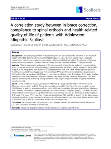
5 Generally a minimum of two structural bracing units (Type A orType B) shall be provided in each overall length of externalwall in each storey, located as closely as possible to theexternal corners (see the code for rules of exceptions); One Type B unit equals two Type A units; Bracing units need to be installed at right angles to the wallarea of elevation (ie parallel to wind direction) for which thebracing was defined.Clause 1.7(f) of AS 1684.4 states that the design capacitiesare 3kN per 900mm for Type A bracing units and 6kN per900mm for Type B. These are Ultimate Limit State (ULS) figures.2.2.2 Nominal BracingCladding not fixed in accordance with this manual, or wallframes not connected to the structure in accordance with thismanual, is nominal bracing. Respectively a 7m length ofsingle-sided nominal bracing or a 4m length of double-sidednominal bracing constitutes one Type A bracing unit.Figure 1: Type A Nailing Detail2.2.3 Structural BracingApart from using HardiBraceTM Sheet Bracing as structuralbracing as per Clauses 2.2.6 and 2.2.7 below, Type A and Bunits can also be achieved with minimum 6mm thick JHFCsheets as detailed in Clause 2.2.8 of this manual. In thissimplified method, bracing units must not be less than900mm wide.2.2.4 Bracing Panels Wider than 900mmBracing units are generally based on a standard width of 900mm.For wider walls than this, the bracing capacity is increased indirect proportion to the installed width divided by 900. Forexample, a 1200mm wide section is equivalent to 1200/900 or1.33 times the bracing resistance of the 900mm unit.2.2.5 Tie-Down RequirementsIn order to provide structural bracing resistance, the bracingpanels must be adequately tied-down to the floor system. Fortie-down requirements, refer to AS 1684.4 Clause 8.3.2.7(bottom) and Clause 8.3.2.8 (top).2.2.6 Type A Bracing UnitsTo achieve Type A bracing capacity (3kN/900mm), fix theHardiBraceTM Sheet Bracing in accordance with Figure 1,Section 5 and Clause 2.2.5 of this manual.2.2.7 Type B Bracing UnitsTo achieve Type B bracing capacity (6kN/900mm), fix theHardiBraceTM Sheet Bracing in accordance with Figure 2,Section 5 and Clause 2.2.5 of this manual.Figure 2: Type B Nailing DetailNote: Nails along the top and bottom plates should be 25mm fromthe edge of the sheet for 50mm thick plates. When 38mm nominalthick plates are used, reduce edge distance to 20mm.2.2.8 Other James HardieCladding ProductsType A or Type B bracing capacities may be achieved withother James Hardie cladding products: To achieve Type A bracing capacity with 6mm JHFC sheetsas defined at Clause 1.2 of this manual, fix sheets in accordancewith Figure 1, Section 5 and Clause 2.2.5 of this manual; To achieve Type B bracing capacities with 6mm JHFC sheetsas defined at Clause 1.2 of this manual, fix sheets in accordancewith Figure 2, Section 5 and Clause 2.2.5 of this manual.The bracing rules and methods of determining therequired number of bracing units remains the same aspreviously described.
2. Bracing for Timber Framing in Accordance withAS 1684-1999 continued62.3 Conventional Limit State Design2.3.1 Design ProcedureFor a building outside the scope of the Simplified Method, usethe procedure given in both AS 1684.2 and AS 1684.3. In bothparts of the code, Clause 8.3.1 states that bracing shall bedesigned and provided for each storey of the house (and subfloorwhere required) in accordance with the following procedure:(a)Determine the wind classification (see the code Clause 1.6and AS 1170.2 or AS 4055);Table 1: ULS Design Bracing Capacity ofJames Hardie Fibre CementCladding on Timber Frames (kN/m)HardiBraceTM Sheet Bracing fixed withstandard nail pattern (see Figure 1)3.3HardiBrace Sheet Bracing fixed withclose-nailed pattern (see Figure 2)6.6TM6mm JHFC sheets, single-sided, fixedvertically as per standard HardiBraceTMSheet Bracing (see Figure 1)3.3(b)Determine the wind pressure (see the code Clause 8.3.2);6mm JHFC sheets, single-sided, fixedvertically as per close nailed HardiBraceTM(c)Determine the area of elevation (see the code Clause 8.3.3and Figure 8.2);Sheet Bracing (see Figure 2)6.6(d)Calculate racking force (see the code Clause 8.3.4);(e)Design bracing systems (for walls, see the code Clause 8.3.5and subfloors see the code Clause 8.3.6);6mm JHFC sheets, single-sided, fixedvertically, (see Figure 3, 4 or 5b), orhorizontally with set joints (see Figure 5a)2.86mm JHFC sheets double-sided, fixedvertically (see Figure 3, 4 or 5b)4.06mm JHFC sheets double-sided, fixedhorizontally with set joints (see Figure 5a)4.06mm JHFC sheets, fixed vertically(see Figure 3, 4 or 5b) or horizontally withjoints set (see Figure 5a) JHFC planks orweatherboards on other side (see Figures 6 & 7)3.2JHFC planks or weatherboards on oneside only (see Figure 6 & 7)2.0(f)Check even distribution and spacing (see the code Clauses8.3.6.6 and 8.3.6.7 and the code Tables 8.18 and 8.19);(g)Check connection of bracing to roof/ceilings and floors (seethe code Clauses 8.3.6.9 and 8.3.6.10).Instead of proportioning bracing units required versus thoseprovided, the actual racking shear capacities of the bracingpanels are added up and made to exceed the total rackingforce calculated. All pressures and forces are Ultimate LimitState (ULS) figures.For permissible stress capacity divide by 1.52.3.2 Nominal BracingNotes for Table 1:The two categories, structural wall bracing and nominal wallbracing, exist in this method too and the same rules apply inthat nominal bracing (as defined at Clause 2.1.2 of thismanual) may provide no more than 50% of the requiredbracing capacity.The ULS capacity of nominal bracing walls is given by thecode as 0.45kN/m for single-sided walls and 0.75kN/m fordouble-sided walls. The minimum length for which nominalbracing capacity may be claimed is 450mm.2.3.3 Structural BracingTable 1 provides the ULS design capacities for the JamesHardie fibre cement products that may be used as designatedstructural bracing in this procedure.Where greater bracing capacities are required, anchor rodsmay be used and the values in Table 4 (in Section 3 of thismanual) claimed.1. If the bracing panel occurs in isolation within a length of wall andis not connected to any cross-wall, then the capacity given inTable 1 must be reduced by 30%.2. For definition of 6mm JHFC sheets see the note at Clause 1.2 ofthis manual. Thicker sheets are assumed to provide at least thetabulated value.3. If JD5 grade timber is used in the framing, then the capacity givenin Table 1 must be reduced by 12.5%.4. Butt joints are permitted in vertical sheets provided that both sheetedges are fixed to a nogging with fasteners at the same spacingas nominated for the top and bottom edges.5. For horizontally fixed sheets, if edges at a butt joint are not fixedto a nogging behind the joint, then the joint needs to be properlytape-set in order to claim the tabulated design bracing capacity.
72.3.4 Wall Height & Capacity ModificationThe capacity of bracing walls is given for a standard wallheight of 2700mm and decreases as the height increases.Refer to Clause 8.3.6.4 of both Parts 2 and 3 of the code,interpreted as in Table 2.2.3.6 Location, Distribution & Spacingof Bracing WallsRefer to Clause 8.3.6.6 of both Parts 2 and 3 of the code forrequired location and distribution and Clause 8.3.6.7 forspacing rules.2.3.7 Tie-Down RequirementsTable 2: Reduction Factors for HeightPanel Height(mm)Bracing ReductionFactor27001.030000.933000.836000.75Note: Intermediate values may be interpolated.2.3.5 Panels Less Than 900mm WideGenerally the minimum width of a designated bracing panel is900mm, although exceptions are permitted with reference toClause 8.3.6.5 of both Parts 2 and 3 of the code. This isinterpreted in Table 3.Table 3: Reduction Factors for WidthBracing Panel (mm)Length of NarrowBracing 000.334500.30Note: Ensure that an intermediate stud is used for bracing panelsover 600mm in width.In order to achieve structural bracing resistance (as defined atClause 2.1.2 of this manual) the bracing panel needs to betied into the structure. For tie-down requirements, refer toClause 8.3.6.9 (top of wall) and Clause 8.3.6.10 (bottom ofwall) in both Parts 2 and 3 of the code.
2. Bracing for Timber Framing in Accordance withAS 1684-1999 continued82.3.8 Other James HardieCladding ProductsThe 6mm JHFC sheet products (as defined at Clause 1.2 ofthis manual) as well as the plank and weatherboard rangeprovides structural bracing capacity as given in Table 1.Fixing details for the different products are given below.(a)HardiFlexTM Sheets, PineRidgeTM Lining &PanelCladTM Sheets(b)HardiTexTM Base SheetsNon-Cyclonic Areas: Sheets fixed vertically in accordancewith Figure 4, Section 5 and Clause 2.3.7 of this manual willachieve the bracing capacities stated in Table 1.Cyclonic Areas: Sheets fixed vertically along with anchorrods in accordance with Figure 4, Section 5 and Clause 3.3 ofthis manual will achieve the values stated in Table 4.Non-Cyclonic Areas: Sheets fixed vertically in accordancewith Figure 3, Section 5 and Clause 2.3.7 of this manual willachieve the bracing capacities stated in Table 1.Cyclonic Areas: Sheets fixed vertically along with anchorrods in accordance with Figure 3, Section 5 and Clause 3.3 ofthis manual will achieve the values stated in Table 4.Figure 4: Nailing Detail for HardiTexTM Base SheetsFigure 3: Nailing Detail for HardiFlexTM Sheets,PineRidgeTM Lining or PanelCladTM Sheets
9(c)VillaboardTM & VersiluxTM LiningsNon-Cyclonic Areas: Sheets fixed vertically or horizontally inaccordance with Figure 5, Section 5 and Clause 2.3.7 of thismanual will achieve the bracing capacities stated in Table 1.Cyclonic Areas: Sheets fixed vertically or horizontally alongwith anchor rods in accordance with Figure 5, Section 5 andClause 3.3 of this manual will achieve the values stated inTable 4.(d)Planks & Weatherboards External CladdingNon-Cyclonic Areas: The bracing capacity stated in Table 1applies to all JHFC planks and weatherboards, when fixed inaccordance with Figure 6, Section 5 and Clause 2.3.7 ofthis manual.Cyclonic Areas: The bracing capacity stated in Table 4applies to all JHFC planks and weatherboards, when fixed alongwith anchor rods in accordance with Figure 6, Section 5 andClause 3.3 of this manual.In both the above cases, JHFC planks and weatherboardsmust be fixed at 150mm maximum centres along top andbottom plates as shown in Figure 7.(a) HorizontalFigure 6: Nailing Detail for HardiPlankTM or PrimeLineTMWeatherboards(b) VerticalFigure 5: Nailing Detail for VillaboardTM and VersiluxTM LiningsFigure 7: Nailing Spacing Detail for JHFC Planks orWeatherboardsNote: For details of tiling over these wall linings, refer to theJames Hardie Internal Linings Range Fixing Manual.Note:1. PrimeLineTM Summit and Newport Weatherboards use theHardiLockTM fixing system and are not suitable for bracing.2. PrimeLineTM Chamfer and Heritage Weatherboards are unsuitablefor use as structural bracing unless fixed such that nails passthrough both planks at the overlaps.
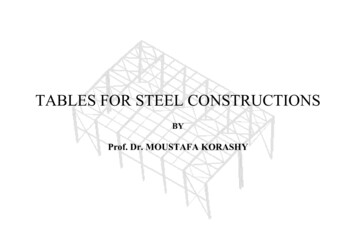
3. Bracing for Timber Framing with10Anchor Rods3. The capacities apply to bracing sheets up to 2700mm high and not3.1 Introductionless than 900mm wide. If different, refer respectively to ClausesThis section details James Hardie fibre cement sheet claddingused for bracing with timber framing and anchor rods,specifically for winds in cyclonic areas. These rods provideresistance against uplift forces and add to the rackingcapacity of the wall panels.Bracing capacities quoted in this section were proved bytesting in consultation with the James Cook CycloneStructural Testing Station.3.2 Bracing Resistance CapacitiesTable 4 provides the ULS design bracing capacities ofHardiBrace Sheet Bracing, 6mm JHFC sheets, JHFC planksand weatherboards used with anchor rods when fixed inaccordance with the relevant parts of this manual.Table 4: ULS Design Bracing Capacity ofJames Hardie Fibre CementCladding on Timber Frames withAnchor Rods (kN/m)HardiBraceTM Sheet Bracing fixed withstandard nail pattern (see Figure 1)6.6HardiBraceTM Sheet Bracing fixed withstandard nail pattern (see Figure 1) 6mm JHFC sheets other side, fixedvertically (see Figure 3, 4 or 5b), orhorizontally with set joints (see Figure 5a)10.06mm JHFC sheets, single-sided, fixedvertically (see Figure 3, 4 or 5b) orhorizontally with set joints (see Figure 5a)5.36mm JHFC sheets,double-sided, fixedvertically (see Figure 3, 4 or 5b) orhorizontally with set joints (see Figure 5a)7.3JHFC planks or weatherboards (see Figure 6 and 7) 6mm JHFC sheets other side, fixed vertically (seeFigure 3, 4 or 5b) or horizontally with set joints (seeFigure 5a)6.6JHFC planks or weatherboards, single-sided(see Figure 6 and Figure 7)2.42.3.4 and 2.3.5 of this manual.4. For horizontally fixed sheets, if edges at a butt joint are not fixedto a nogging, then the joint needs to be properly tape-set in orderto claim the tabulated design bracing capacity.3.3 Anchor Rod Detail and Tie-DownAnchor rods must be 12mm diameter, full-length mild steel(M12) rods tying the wall top plate through the frame cavity tothe sub-structure.A standard 38mm diameter flat round washer must be usedunder each nut.Anchor rods must be placed at both ends of each section ofthe bracing wall and at not more than 2.4m centres.Anchor rods must be located within 100mm of the adjacentface of the stud ends. See Figure 8.Between anchor rods, one M10 hold-down bolt must beprovided at a maximum of 1.2m centres to further fix thebottom plate to the sub-structure.Fixing of the timber frames into the structure (ie "tie-down")must comply with government building regulations and/orAS 1684.3-1999. Refer to the code Clauses 8.3.6.9 (top) and8.3.6.10 (bottom).For permissible stress capacity divide by 1.5Notes for Table 4:1. For definition of 6mm JHFC sheets see Clause 1.2 of this manual.Thicker sheets are assumed to provide at least the tabulated value.2. The tabulated bracing strengths relate to 600mm maximum studcentres.Figure 8: Anchor Rod Detail
11
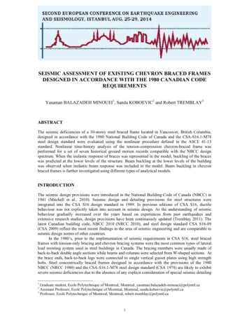
4. Bracing for12Steel Framing4.1 IntroductionExtensive testing conducted at the James Hardie R&DLaboratory and at the James Cook Cyclone Structural TestingStation has formed the basis of the information and thedesign capacities quoted in this section.4.2 Bracing Resistance CapacitiesTable 5 shows the bracing capacity of HardiBrace SheetBracing and other James Hardie cladding products whenfixed to 0.55mm and 0.75mm light gauge steel frames or1.2mm and 1.6mm medium gauge, welded steel frames.Note: Only the values tested are shown in Table 5. Other valuesmay, in certain instances, be interpolated with experience andFigure 9: Screw Spacing Detaildue diligence.The bracing capacities are achieved by using the fixingmethods outlined in Clause 4.3 and Section 5 of this manual.Notes for Table 5:1.Design capacities were determined in accordance withAS 3623-1993 for 2700mm high panels unless noted otherwise.HardiBraceTM Sheet Bracing must not be used as exposed,finished, external cladding.2.The minimum length of a bracing wall or panel must be900mm. The maximum wall length to which the capacitiesapply is 3600mm.Bracing capacity can only be claimed for JHFC plank orweatherboard cladding if screws pass through both planks. SeeFigure 6.3.For riveted frames of 1.2 and 1.6mm gauge, the tabulated bracingcapacities must be multiplied by a factor of 0.8.4.3 Framing Connections0.55mm to 0.75mm light gauge steel frames:The studs need to be fixed to the top and bottom tracks byscrews, rivets, bolts or mechanical crimping.0.75mm to 1.6mm medium gauge steel frames:The connections may be welded or riveted, noting that thedesign bracing capacity is 20% lower for the riveted frames.4.For definition of 6mm JHFC sheets see Clause 1.2 of this manual.Thicker sheets are assumed to provide at least the tabulated value.5.Butt joints are permitted in vertical sheets provided that both sheetedges are fixed to a nogging with fasteners at the same spacingas nominated for the top and bottom edges.6.For horizontally fixed sheets: if edges at a butt joint are not fixedto a nogging, then the joint needs to be properly tape-set in orderto claim the tabulated design bracing capacity.4.4 Tie-Down Requirements0.55mm to 0.95mm light gauge steel frames:Provide M10 minimum hold-down bolts with 50 x 50 x 3mmdistribution washers at the two outside frame studs and M6minimum hold-down bolts with 32mm diameter 2.5mm thickround washers at the interior studs. All bolts to be placedwithin 45mm of the stud.0.95mm to 1.6mm medium gauge steel frames:Provide M12 minimum hold-down bolts with 75 x 70 x 6mmdistribution washers at 900mm centres and within 70mm ofthe face of studs.7.For external sides of walls, 6mm VillaboardTM lining must be replacedby properly coated 6mm HardiFlex or 7.5mm HardiTexTM Sheets.
13Table 5: ULS Bracing Capacity of James Hardie Fibre Cement Cladding on Steel FramesMaterialFixing DetailsStudSpacing(mm)Screw Spacing (mm)A/B/C (see Figure 9)Bracing Capacity (kN/m)Light GaugeSteel Frames0.55mm0.75mmWelded SteelFrames (see Note 3)1.2mm1.6mmBMT Studs BMT Studs BMT Studs BMT Studs5mm HardiBraceTMSheet Bracing(see Note 1)7.5mm HardiTexTMBase Sheet6mm JHFC Sheets(see Note 4)(see Note 7)7.5mm JHFCplanks orweatherboards600100/100/1505.46.0 d, fixedvertically, joints(if any) not 0/200/200---7.5Single-sided600See Note 2 andFigures 6 & 72.12.2--450See Note 2 andFigures 6 & 7---2.4300See Note 2 andFigures 6 & 7---3.6600See Note 2 andFigures 6 & 7For 6mm JHFCsheets: 200/200/2003.94.0--450See Note 2 andFigures 6 & 7For 6mm JHFCsheets: 200--5.8-Sing
2 Bracing for Timber Framing in Accordance with AS1684-1999 4 2.1 Design Methodology 4 2.2 Simplified Design Method 4 2.3 Conventional Limit State Design 6 3 Bracing for Timber Framing with Anchor Rods 10 3.1 Introduction 10 3.2 Bracing Resistance Capacities 10 3.3 Anchor Rod Detail and Tie-Down 10 4