Transcription
TABLES FOR STEEL CONSTRUCTIONSBYProf. Dr. MOUSTAFA KORASHY
TABLES FOR STEEL CONSTRUCTIONSBYProf. Dr. MOUSTAFA KORASHYCHECKED BYDr. SHERIF IBRAHIMEng. MOHAMED KORASHY2001
CONTENTSList of symbolsiIntroductioniiHot Rolled Sections1Combined Hot Rolled Sections26Cold Formed Sections46Combined Cold Formed Sections50Bolts55Sample of Corrugated Sheets66Accessories76Cranes79Welding Symbols86Miscellaneous90
LIST OF SYMBOLSa (mm): Length of long leg for unequal angle.Iy (cm4): Moment of inertia about Y-Y axis.b (mm): Length of short leg for unequal angle,or flange width.Iy upper flange (cm4): Moment of inertia for upper flange about Y-Y axis.J (cm4): Torsion constant.b1 (mm): Width of upper flange for unsymmetrical welded I-sections.r (mm, cm): Radius of inner fillet for cold formed section,or Radius of gyration for symmetrical section.b2 (mm): Width of Lower flange for symmetrical welded I-sections.c (mm): Height of curved part including flange thickness for channel and Isections.r1 (mm): Radius of fillet between web and flange.ru (cm): Radius of gyration about U-U axis.D (mm): Outer diameter of pipe.rv (cm): Radius of gyration about V-V axis.d (mm): Height of web for built-up I-sections.rx (cm): Radius of gyration about X-X axis.dmax. (mm): Maximum diameter of bolt to be used.ry (cm): Radius of gyration about Y-Y axis.e (mm): Distance measured from outer surface to neutral axis of section.ex (mm): Distance from bottom surface to X-X axis.s (mm): Thickness of web,or Thickness of angle legey (mm): Distance from outer surface to Y-Y Axis.S (cm3): Elastic modulus of section.h (mm): Height of section.Sv (cm3): Elastic modulus of section about V-V axis.I (cm4): Moment of inertia for symmetrical section.Sx (cm3): Elastic modulus of section about X-X axis.Iu (cm4): Moment of inertia about U-U axis.Sxb (cm3): Elastic modulus of bottom extreme fibers about X-X axis.Iv (cm4): Moment of inertia about V-V axis.Sxt (cm3): Elastic modulus of top extreme fibers about X-X axis.Ix (cm4): Moment of inertia about X-X axis.iM. Korashy
Sy (cm3): Elastic modulus of section about Y-Y axis.Sy upper flange (cm3): Elastic modulus of upper flange about Y-Y axis.t (mm): Thickness of flange,or Wall thickness.tG (mm): Thickness of gusset plate.u1, u2 (cm): Distance between outer fibers of an angle to V-V axis.Um (m2/m\): Surface area per unit length.Ut (m2/t): Surface area per unit weight.v, v1,&v2 (cm): Distance between outer fibers of an angle to U-U axis.w, w1 (mm): Distance determining bolt hole location relative to the section.Xm (cm): Distance between centroid of a channel and its shear center.iiM. Korashy
IntroductionThe aim of presenting these tables is to provide the structural engineers withwide range of information required in designing steel structures. Previously,a steel designer had to search in many tables, handbooks, manuals, etc. tocollect the necessary information needed to complete his/her design.These tables are divided into nine chapters. Chapter one provides thegeometrical properties of common hot rolled sections which includes thefollowing: Equal and unequal angles: primarily used in trusses for resistingaxial forces. Channels (UPN): used as truss members and purlins or side girts. I-sections (IPN, IPE, HEA, HEB, HEM):IPN section is suitable for beam subjected to bending moment aboutits major axis.IPE section used mainly for beams or beam column.HEA, HEB, and HEM sections are primarily used for memberssubjected to bi-moments or for heavy beam-columns. T-sections are produced by cutting I-sections into two halves. Theyare used as brackets, truss members or light beams.iii
Pipes and hollow sections: primarily used as truss members inwelded trusses.Hollow square and rectangular sections, sometimes used as roofpurlins or light beam-columns. Flat plates used in connections as head plates, gusset plates or it canbe utilized in composing built-up section. Rails: used mainly in tracks of moving structures such as cranebridge.In unprecedented presentation of section properties in the Egyptian practice,Chapter two introduces the geometric properties for combined hot rolledsections and built–up welded sections.This chapter provides the properties for the following combined sections: Two equal or unequal angles back to back:Used mainly as lower or upper chord of trusses, or bracing members. Two channels back to back:Used mainly as lower or upper chord in heavy trusses. Two channels toe to toe:Used as beam-column especially when the buckling lengths in-planeand out of plane are nearly equal.iv
IPE and UPN:This section is used primarily as section for crane girders. The“UPN” section is provided at the top flange where the lateral shockof the crane bridge is applied. Symmetrical welded I-Section:This section consists of three parts welded to form symmetricalI-sections. It is used mainly for beams or beam-columns. Unsymmetrical welded I-sections:This section is formed in away to make the upper flangeapproximately twice the lower flange. Thus it is suitable for cranegirders where the lateral shock is applied at the upper flange. Thesection might also be used for composite construction when theupper and lower flanges are switched.Chapter three introduces the geometrical properties of cold-formed steelsections, these sections includes: Channels (stiffened and unstiffened) and Z sections (with straightlips and with inclined lips): These sections are used mainly for roofpurlins and side girts. Sometimes, they can be used in light trusses asweb members.v
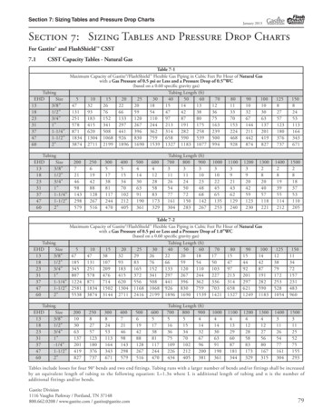
Chapter four provides the geometrical properties for combined cold-formedsections. These sections includes: Two channels back to back:Used as lower or upper chord in light trusses or in bracing members. Two channels toe to toe:Used in light beam columns or as eave struts I bracing system.Chapter five provides complete information about the size, weight, and griplength of ordinary and high strength bolts. It also provides the dimensionand weight of washers and nuts used for each type of bolts.This chapter also includes the dimension and the weight of anchor boltswith various configurations.Chapter six provides the geometrical properties of sample of corrugatedsheets whether they are single layer, sandwich panels, or metal decking steelsheets. In this chapter the allowable spacing between purlins is alsoprovided based on the strength and serviceability criteria.Chapter seven includes samples of the wheel loads of crane bridgescovering the following ranges of crane capacities: Light cranes with capacity range from 0.5 to 6.3 ton. Normal cranes with capacity range from 2.0 to 25 ton. Heavy cranes with capacity range from 25 to 63 ton.vi
Chapter eight provides the common symbols used in welding constructions.Chapter nine includes various data covering the following areas: Conversion tables used to convert engineering units from imperial toSI or metric systems and vice versa. Dimensions of aircraft with various types to assist in choosing theconfiguration of aircraft hangar. Geometrical properties of common shapes in engineering practice.vii
HOT ROLLED SECTIONSEQUAL ANGLESHALF I.P.E.UNEQUAL ANGLEHALF H.E.A.CHANNELS (U.P.N)HALF H.E.B.I.P.N.PIPESI.P.E.HOLLOW SQUARE SECTIONSH.E.A.HOLLOW RECTANGULAR SECTIONSH.E.B.PLATESH.E.M.RAILS1M.Korashy
YvUVu2sdu1vSW1XeXeaaUVW2aEQUAL ANGLESYSizeWeight Areaasemmmm kg/m 85.426.911.696607.099.031.7788.69 11.10 1.85106.838.701.857657.739.851.8988.62 11.00 1.939N.A. not available for this angle xis X-X and 0 3.311.3311.00 3.051.5112.80 3.511.5014.60 4.151.4914.70 3.701.6617.80 4.401.6622.10 5.721.6422.80 5.291.8229.10 6.881.8034.90 8.411.7833.40 7.131.9637.50 8.131.9541.30 9.041.942Axis 335.631.317.091.528.641.519.981.4912.40 1.7014.50 1.6916.40 1.6717.40 1.9020.40 1.8923.10 1.8823.30 2.0927.40 2.0834.80 2.0636.10 2.2946.10 2.2655.10 2.2353.00 2.4759.40 2.4665.40 2.44Axis M16M16M16M16M16M16Surface AreaUmUt-22\x10 m rashy
u2sVu1vSdUvYW1XeXeaaUVW2aEQUAL ANGLESYSizeWeight Areaasemmmm kg/m cm2cm7.389.401.977709.34 11.90 2.05911.20 14.30 2.13117.94 10.10 2.037759.03 11.50 2.13811.10 14.10 2.21109.66 12.30 2.2688011.90 15.10 2.341014.10 17.90 2.411212.20 15.50 2.5499014.70 18.70 2.621117.10 21.80 2.701315.10 19.20 2.821010017.80 22.70 2.901220.60 26.20 2.981416.60 21.20 3.071011019.70 25.10 3.151222.80 29.00 3.211421.60 27.50 3.401212023.30 29.90 3.441326.60 33.90 3.5115N.A. not available for this angle 93.933.984.264.274.31Axis X-X and .633Axis 6254.597054.56Axis 4M24M20M20M20M20M20M20Surface AreaUmUt-22\x10 m 621.7020.1317.60M.Korashy
YvUVu2sdu1vSW1XeXeaaUVW2aEQUAL 61820151719161820221618202428Weight Areakg/m cm223.60 30.0027.20 34.7030.90 39.3027.50 35.0031.40 40.0031.60 40.3033.80 43.0035.90 45.7040.10 51.0044.20 56.3036.20 46.1040.70 51.8045.10 57.5043.50 55.4048.60 61.9053.70 68.4058.60 74.7048.50 61.8054.30 69.1059.90 76.4071.10 90.6082.00 10.60 6.076.176.286.3511.30 6.466.587.1112.70 7.227.337.447.807.9214.10 7.28Axis X-X and 02706.024Axis .7841507.7545407.7252807.6459907.57IvAxis face AreaUmUtx10-2 2.0316.2014.5013.1011.049.57M.Korashy
VUdV1YaW1W2exSu2XsV2XUNEQUAL ANGLESaAUeybu1bVammSizebmmWeightAreas2mmkg/m 611.4086.858.736100508.9911.50811.10 14.10108.7711.2071006511.10 14.20913.40 17.1011N.A. not available for this angle 1.511.591.67Dimensionsv1v2cmcm2.04 1.512.02 1.522.61 1.772.57 1.803.09 2.233.07 2.263.05 2.273.90 2.673.83 2.724.08 3.014.06 3.024.04 3.035.14 3.735.10 3.775.06 3.805.21 3.535.15 3.576.14 4.506.11 4.546.50 4.396.48 4.446.43 4.496.83 4.916.78 4.946.74 721.772.032.132.221.551.652.462.561
Used as lower or upper chord in light trusses or in bracing members. Two channels toe to toe: Used in light beam columns or as eave struts I bracing system. Chapter five provides complete information about the size, weight, and grip length of ordinary and high strength bolts. It also provides the dimension and weight of washers and nuts used for each type of bolts. This chapter also .