Transcription
Local Exhaust Ventilation(LEV) Guidance
Our vision:A country where workersafety, health and welfareand the safe managementof chemicals are central tosuccessful enterprisePublished in January 2014 by the Health & Safety Authority, The Metropolitan Building, James Joyce St., Dublin 1.
ContentsChapter 1Summary . . . . . . . . . . . . . . . . . . . . . . . . . . . . . . . . . . . . . . . . . . . . . . . . . . . . . . . . . . . . . . . 2Chapter 2Introduction . . . . . . . . . . . . . . . . . . . . . . . . . . . . . . . . . . . . . . . . . . . . . . . . . . . . . . . . . . . . 4Risk Assessment . . . . . . . . . . . . . . . . . . . . . . . . . . . . . . . . . . . . . . . . . . . . . . . . . . . . . 5Control . . . . . . . . . . . . . . . . . . . . . . . . . . . . . . . . . . . . . . . . . . . . . . . . . . . . . . . . . . . . . . 5Chapter 3What is Local Exhaust Ventilation (LEV)? . . . . . . . . . . . . . . . . . . . . . . . . . . . . . . . . . . 7Chapter 4Types of Local Exhaust Ventilation (LEV) . . . . . . . . . . . . . . . . . . . . . . . . . . . . . . . . . 19Chapter 5Misconceptions . . . . . . . . . . . . . . . . . . . . . . . . . . . . . . . . . . . . . . . . . . . . . . . . . . . . . . . . 31Chapter 6Properties of Airborne Contaminants . . . . . . . . . . . . . . . . . . . . . . . . . . . . . . . . . . . 35Chapter 7Flow Rates . . . . . . . . . . . . . . . . . . . . . . . . . . . . . . . . . . . . . . . . . . . . . . . . . . . . . . . . . . . . . 38Chapter 8How to Select Local Exhaust Ventilation (LEV) . . . . . . . . . . . . . . . . . . . . . . . . . . . 40Chapter 9Installation and Maintenance of LEV . . . . . . . . . . . . . . . . . . . . . . . . . . . . . . . . . . . . 43Chapter 10 Information and Training for Employees . . . . . . . . . . . . . . . . . . . . . . . . . . . . . . . . 47Chapter 11 Keeping Records . . . . . . . . . . . . . . . . . . . . . . . . . . . . . . . . . . . . . . . . . . . . . . . . . . . . . . . 49Chapter 12 Examining & Monitoring Performance . . . . . . . . . . . . . . . . . . . . . . . . . . . . . . . . . . 50Chapter 13 Main Legal Requirements . . . . . . . . . . . . . . . . . . . . . . . . . . . . . . . . . . . . . . . . . . . . . . . 57Chapter 14 Standards . . . . . . . . . . . . . . . . . . . . . . . . . . . . . . . . . . . . . . . . . . . . . . . . . . . . . . . . . . . . . . 61Chapter 15 References . . . . . . . . . . . . . . . . . . . . . . . . . . . . . . . . . . . . . . . . . . . . . . . . . . . . . . . . . . . . . 62Chapter 16 Further Reading . . . . . . . . . . . . . . . . . . . . . . . . . . . . . . . . . . . . . . . . . . . . . . . . . . . . . . . . 63Chapter 17 Useful Contacts . . . . . . . . . . . . . . . . . . . . . . . . . . . . . . . . . . . . . . . . . . . . . . . . . . . . . . . . 64Chapter 18 Glossary . . . . . . . . . . . . . . . . . . . . . . . . . . . . . . . . . . . . . . . . . . . . . . . . . . . . . . . . . . . . . . . . 65Drawings/pictures/diagrams courtesy of the HSE/HSL UK & IOSH
Local Exhaust Ventilation (LEV) GuidanceChapter 1SummaryThis guidance is written for employers, managers, employees and their safety representatives andthose who provide, install and maintain local exhaust ventilation (LEV) systems.In preventing exposure to harmful substances in the workplace, there is a hierarchy of controlmeasures that must be considered, commencing with the elimination or substitution of the hazardor, where these options are not possible, the hazard must be controlled by engineering means. Localexhaust ventilation (LEV) is one such engineering control measure.LEV is an engineering system designed to reduce employee exposure to airborne contaminants (dust,mist, fume, vapour, gas) in the workplace by capturing the emission at source and transporting it to asafe emission point or to a filter/scrubber. Employers need to work with designers, suppliers, installersand employees to effectively control exposure to airborne contaminants.Suppliers must provide LEV that is fit for purpose, is shown to work and continues to work.The employer (the LEV owner) must ensure controls are adequate. Everyone, including suppliers andusers of the LEV, must be competent in the use of the LEV system.The main LEV elements are: A hood of some kind, where the contaminants enter the system Ducting, which safely transports the contaminants to a filter/cleaner/exhaust point Air cleaner/filter/scrubber Air mover: a fan to power the system Discharge: a safe point of air exhaustWhen using LEV to control exposure, the employer must thoroughly assess the hazards to becontrolled and be satisfied with the following: the LEV system is fit for purpose; it is being usedcorrectly by trained employees; the system is regularly maintained to remain effective; and records arekept to demonstrate the system is both effective and ongoing. Having a good understanding of whathazards need to be controlled is crucial to ensure that the initial design is capable of achievingadequate control.2Chapter 1
Local Exhaust Ventilation (LEV) GuidanceWhen installing LEV: Identify and assess the hazard(s) to be controlled Identify competent contractors to install the system Provide the installer with clear requirements or specifications Review and ensure that the design and its specifications are satisfactory Obtain and retain all the related paperwork in design specifications, including the commissioningreport (hand book) Ensure when the system is installed that it meets the design specifications Maintain the system and measure performance regularly Train employees in the proper use of the LEVChapter 13
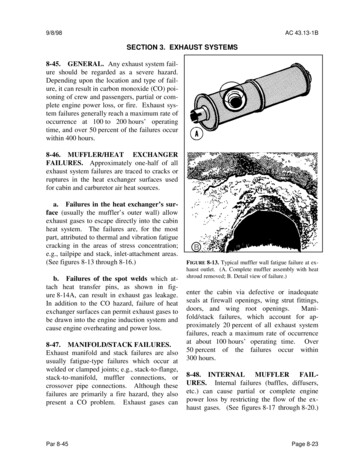
Local Exhaust Ventilation (LEV) GuidanceChapter 2IntroductionLocal exhaust ventilation (LEV) is an engineering system frequently used in the workplace to protectemployees from hazardous substances. To have an effective system it is important that it is welldesigned and installed, used correctly and properly maintained. All the participants, from designer toend-user need to work together to provide an effective system.Common Problems Employers are often unaware their employees are being over-exposed to hazardous substancesor that existing controls may be inadequate Sources of exposure are missed Employers (and suppliers) are over-optimistic about the effectiveness of the controls Existing controls have deteriorated Controls are not used correctlyEmployers need to work with designers, suppliers and employees to ensure effective control, to avoidexpensive mistakes and to control exposure effectively. Suppliers must provide LEV that is fit forpurpose, is shown to work and continues to work. The employer (the LEV owner) must ensure controlsare adequate. Everyone, both suppliers and users of the LEV, must be competent in the operation ofthe LEV system.Adverse health effects can occur when employees are exposed to occupational hazards such as dusts,fumes and vapours (chemical or biological agents). The effects of exposure to a hazard depend on thefrequency, duration and degree of exposure: some substances can cause immediate health effects,such as carbon monoxide poisoning; others, such as asbestos, can have a long latency period. Thepotential for exposure to any chemical or biological agent needs to be assessed in each place of work.Employees can contract occupational illnesses and diseases and develop these because they breathein too much dust, fumes or other airborne contaminants at work, often because control measuresare not in place or do not work well enough. Many industries can be affected, including chemicalprocessing, pharmaceutical, biotechnology, woodworking, welding, paint-spraying, stonemasonry,engineering and foundry work. The purpose of this guidance is to describe how to control gas, vapour,dust, fume, mist, in other words aerosols (hazardous agents), in the workplace air by using localexhaust ventilation (LEV), i.e. extracting the contaminant and preventing exposure.4Chapter 2
Local Exhaust Ventilation (LEV) GuidanceAlthough this guide concentrates on local exhaust ventilation (LEV), it is important to remember thatthe control or lack of general ventilation, including general supply and exhaust ventilation, can affectthe performance of the LEV. For instance, a draught from an open door may challenge a welding hoodextraction performance, or an insufficient supply of air in a closed system will ‘starve’ an exhaustingLEV system. Therefore there are many factors that need to be considered when installing controls.Risk AssessmentA risk assessment involves (1) anticipating; (2) recognising; (3) evaluating; and (4) controlling thehazards to which the employee might be exposed. The Authority has advice on its website (www.hsa.ie) on how to carry out an assessment.When the employer has completed a risk assessment, evaluated the risks and determined thepotential hazards, control methods need to be considered. As well as health hazards, there may beflammability, reactivity and/or physical hazards (e.g. excessive heat).ControlWhen control is being considered there is a standard hierarchical approach. Can the processbe changed so that the hazardous chemical agent can be eliminated or substituted with a lesshazardous one? Can the process be modified to reduce risk of exposure (for example can the processtemperature be lowered to reduce vapour release)? Are engineering controls appropriate? Canstructures such as hoods, booths, enclosures or local exhaust ventilation be used to contain or capturehazardous chemical agent emissions? Administrative controls are used to minimise employeeexposure by time planning and rotation. The final control in the hierarchy is the use of personalprotective equipment (PPE).Chapter 25
Local Exhaust Ventilation (LEV) GuidanceIn installing controls, the employer should start at the top of the hierarchy before rushing to installlocal exhaust ventilation (LEV), for example. The employer must first determine what is the mosteffective controls measure(s). The installation of any control measure is likely to be expensive (ithas, for example, the potential to introduce operational difficulties), so a thorough review of theeffectiveness of the chosen control method and how employees will interface with the system is vital.The LEV system must be fit for purpose. For example, where the process entails grinding, it is likely thatdust will be propelled from the source and the system needs to be designed to contain and capturethe fugitive dust. Before designing or installing an LEV system, a good understanding of contaminantsand the process demands are necessary. Consideration should be given as to whether the systemwill be required to cope with changing materials processes and, if so, whether you need to build inflexibility for this from the start.The installation of new engineering controls such as LEV may bring its own risks and should beincluded in the overall assessment of operations. How well does the LEV system interface with theemployee, the process and the place of work? For example, the noise generated by new fans/motorsmay need to be considered to prevent over-exposure to noise in the workplace; manual handling orergonomic difficulties may be introduced; it may result in the generation of static electricity becauseof material type; or lack of bonding/earthing may be an ignition source.Once the system is installed as designed, it must be used correctly and not tampered with; it must beregularly performance checked so that its effectiveness in protecting the employee(s) is achieved andmust be maintained as laid down in the risk assessment.In some circumstances, such as woodworking machines, the LEV may be designed as an integral partof the equipment. Therefore, although the design stage is completed in advance, employee trainingmust be applied in all other elements, such as proper use, cleaning and maintenance.6Chapter 2
Local Exhaust Ventilation (LEV) GuidanceChapter 3What is Local Exhaust Ventilation (LEV)?In its simplest terms local exhaust ventilation is an engineering system to protect employees fromexposure to hazardous substances by containing or capturing them locally, at the emission point.Local exhaust ventilation (LEV) is only one of many engineering control options that may be usedto remove and prevent employee exposure to vapour, mist, dust or other airborne contaminants. Tobe effective in protecting the employee(s), it is important that it is of good design, is fit for purpose,is regularly maintained and the system’s performance is monitored. Failure to do so can lead toemployees being exposed because they have the impression that the system is effective when it is not.Poor design and/or maintenance may lead, for example, to leakage in the workplace, causingconcentrated local exposure rather than preventing it. A poorly designed, installed, misused andincorrectly maintained system can become an expensive waste of expenditure and may give a falseimpression of hazard control.Employees must be given training in its use and maintenance to understand its correct use andeffectiveness. Many employers and employees overestimate the effectiveness of the different typesof LEV, and have a poor understanding of the types of conditions that could lead to a reduction in ordepletion of the LEV’s effectiveness.Chapter 37
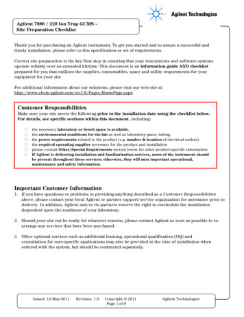
Local Exhaust Ventilation (LEV) GuidanceSupplier & Designer, Installer& CommissionerEmployers/Supervisors/OperatorsLocal ExhaustVentilation (LEV)ParticipantsPerformance & ExaminationCompetent PersonsMaintenance & RepairEngineersLocal Exhaust Ventilation UsersGood design and fit for purposeGood design and being fit for purpose are the crucial initial considerations to ensure the effectivenessof the system. Where the process changes and additions or changes are needed the overall designshould be reconsidered so the system remains effective. Creeping additions and extensions of thesystem can be a temptation for expediency, but lead to totally ineffective systems. If a system isredesigned, it also needs to be re-commissioned.Examples of poor design: The extract fan system is sized too small and the hood cannot contain or capture the contaminants. The fume hood is placed in an area where there is sporadic cross draughts or insufficient supplyair and the inward flow is challenged. A hood may have been designed without proper consideration of the work being done; the fit isincorrect and it may be impossible for the employee to use the system effectively; it may introduceergonomic or manual-handling hazards.8Chapter 3
Local Exhaust Ventilation (LEV) Guidance A fan may be incorrectly placed so that a major section of the ducting is under positive pressure.Where this ducting is within the workplace, any leakage on the positive pressure side has thepotential to expose employees who may or may not be involved in the process and may beunaware of their exposure. Where ducting is wrongly sized, the transport velocity within the duct may be insufficientand contaminant will settle out in the ducting. This can be a serious fire hazard if combustible orflammable contaminants are being extracted. Flammable vapours/materials are being extracted but no consideration has been given to theprevention of a source of ignition or to dilution well below the lower explosion limit. Poor design of exhaust point may cause the contaminants to be captured by the air supply system;for example, instead of being exhausted and diluted, they may enter a downdraught caused byadjacent buildings and re-enter the workplace.Chapter 39
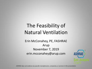
Local Exhaust Ventilation (LEV) GuidanceElements of LEV system:Most systems have the following five elements:1. An inlet/enclosure/hood where the contaminant is captured or contained and enters the LEV.2. Ducting: This conducts air and the contaminant from the hood to the discharge point.3. Air cleaner or filter: This filters or cleans the extracted air. Not all systems need air cleaning.4. Air mover: The fan and motor that powers the extraction system.5. Discharge or exhaust: This releases the extracted air to a safe place.ContaminantHoodDuctingAir cleanerFan10Chapter 3Exhaust
Local Exhaust Ventilation (LEV) GuidanceThe unit in its entirety must be of good design.For example: Leak-proof: leakage on the suction or negative pressure side of the air remover will lead toinefficient extraction and leakage on the positive pressure side and may reintroduce thecontaminant to the workplace. The flow rate of air through the system must be sufficient to achieve the initial capture/containment and carry all contaminants to the purifying/filtering system (transport velocity).Combustible dusts (wood dust, for example), if not extracted properly, can deposit in the ductingand be a fire or explosion risk. Flammable solvents being captured by the system need to bediluted by sufficient air flow to prevent the formation of a flammable mixture. The ducting needs to be structured so as to avoid eddy currents and inefficient flow. For example,it should not have sharp right-angled turns, as this leads to dead areas with no flow. The construction and materials of construction need to be compatible with the contaminantsbeing extracted. For example, where flammable gases or vapours are being extracted, the systemshould not be able to generate a source of ignition. Likely ignition sources could arise from theuse of non-rated electrical equipment such as the air mover, or from the accumulation of staticelectricity from the lack of earthing and bonding and the use of non-conductive materials.Corrosion by the contaminants is another consideration.Chapter 311
Local Exhaust Ventilation (LEV) Guidance1. An Inlet/Enclosure/Hood includes some type of hood or enclosure such as those listed below:12a.cowl for capturing welding fumesb.laboratory fume hood or cupboardc.biological safety cabinetd.paint-spray boothe.down-flow boothf.ventilated hopperg.dust-capturing device at woodworking machineh.pouring stationi.movable/flexible hoodsj.portable hoods with filtersk.abrasive blasting room or cabinetChapter 3
Local Exhaust Ventilation (LEV) GuidanceThe three basic types of hood:HOODReceivingFull enclosureCanopy‘Room’ enclosureOther receiving hoodsCapturingSimple capturing hoodAir jetEnclosingMoveablesourceand hoodPartial enclosure – boothRim or lip extractionPush-pull systemDowndraught tableLow volume high velocity(LVHV)Chapter 313
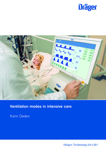
Local Exhaust Ventilation (LEV) Guidance The type of hood or enclosure is influenced by the work being done. The hood or enclosure shouldnot obstruct or cause ergonomic difficulties (e.g. manual-handling limitations or over-reaching). The hood/enclosure may need to be designed to capture/contain dust, fumes, mist, fibres, vapouror gas aerosols. The contaminant cloud or aerosol may be a slow release or a highly energisedrelease caused by a power tool, for example. Dusts from solids being dropped can temporarilyovercome a system.Working zone(green)Capture zone Working zone(yellow)(green)Capture zone Working zone(yellow)(green)Capture zone(yellow)EffectivePartly effectiveInneffective The degree of containment around the emission point is crucial. The hood should be structuredand placed at the emission point so as to entrain/contain the emission. For example, the air-flowrate to a circular extraction duct with no hood attached will fall to about 10% of the in-duct flowrate at one diameter distance from the duct opening. As the distance of the emission point fromthe hood increases, the LEV effectiveness decreases dramatically.14Chapter 3
Local Exhaust Ventilation (LEV) Guidance8 The hood/enclosure must be placed so it does not draw contaminant into the breathing zone of theoperator(s). Neither should it be positioned so that the operator causes an air-flow obstruction.Airflow indicator setup There should be an indicator at the hood to show the system is performing correctly. Fume-hoodcupboard and biological safety cabinet standards require visible indicators. These indicators canhave numbers such as flow rate or negative pressure or colour-coded bands for acceptable ranges.See I.S. EN14175-1 to 7 FUME CUPBOARDS for detailed requirements.Chapter 315
Local Exhaust Ventilation (LEV) Guidance2. Ducting: The hood or inlet devices must be connected to a duct or ducting system, depending onthe complexity of the system which will effectively contain contaminants transported from the inletand efficiently, with proper flow control, deliver the exhaust flow to the discharge.a. The ducting has to be sized and oriented so that the flow within it is efficient, e.g. approachinglaminar flow rather than turbulence. The flow rates within the ducting should be sufficientto transport the contaminant to the outlet or filtering system. Flow rates can vary greatly,depending on the nature of the contaminant. The rate should be sufficient to allow thecontaminant be transported and not deposited on the walls of the ducting, where it canreduce flow efficiency and become a possible fire or explosion hazard, depending on the natureof the contaminant.DR8SmalljoiningangleR not less than11/2 times DFlanged joints8Adequate lengthSlip jointAchieving laminar flowb. It should be of sound and solid construction so that it does not allow inward or outward leakageand will not therefore be corroded by the contaminants being extracted or weather elementswhere ducting is external. Leakage at joints or flanges results in the system not operating asdesigned. It may lead to employee exposure or to uncontrolled release to the environment.c. Ideally, all internal ducting in the workplace should be under negative pressure so that in the eventof any leakage, employees in the workplace are not exposed. In the event of an outward leakageinto the workplace, employees could be inadvertently exposed and, where ducting is extensive,non-involved employees in other areas may be unknowingly exposed.16Chapter 3
Local Exhaust Ventilation (LEV) Guidance3. Air filtering, collection or cleaning system:The contamination removal/filtering system should be fit for purpose. The type of system usedwill be very much dictated by the type of contaminant being extracted and can vary from a simplefilter system to a multi-component system with pre-filters and scrubbers, for example.Whatever the filtering system, it should be designed so that it can cope with the contaminantload and remove/filter it effectively without affecting flow performance. It should be easilychanged, cleaned and maintained without causing exposure to operations or maintenance staff.Following risk assessment, because of the increased potential for exposure and depending on thetype and complexity of the filtering system, it may be necessary to draw up procedures for safeentry to filter housing, and for regular changing, cleaning and maintenance of filters.4. Air mover or fan:The air mover needs to be suitable for use. It will need to provide a sufficient air-flow rate toefficiently extract the contaminant, including a sufficient in-duct velocity to transport thecontaminant to the cleaning/filtering system and prevent flammable material, for example,depositing within the ducting. The air mover should be able to cope with increased pressure as thefiltering element becomes loaded.The air mover should not provide a source of ignition. The air mover and its components should beimpervious to corrosion/abrasion damage by the contaminants.5. Discharge system:The discharge ducting should be placed so that it does not affect any air-supply system. The airbeing exhausted should not be entrained and recirculated into the workplace through the airsupply system.Chapter 317
Local Exhaust Ventilation (LEV) GuidanceAdvantages of LEV Properly positioned LEV and/or well-designed units will capture emissions at source and soprotect the employee from exposure The general supply/exhaust ventilation air volume can be reduced as it is not relied upon todilute contaminants.Disadvantages of LEV If the LEV is incorrectly placed, contaminants can be drawn into (a) the operators’ breathingzone; and (b) the process Emissions drawn into the system must be disposed of safely and without adverse effectson the environment It is an additional system to operate and maintain; otherwise it could become an exposureand/or fire hazard Employees must be properly trained in the system’s correct use, its effectiveness andmaintenance needs.18Chapter 3
Local Exhaust Ventilation (LEV) GuidanceChapter 4Types of Local Exhaust Ventilation (LEV)An inlet/enclosure/hood where the contaminant is captured/contained or enters the LEV.There are many types of hoods depending on requirements: capturing hood, small enclosure, walkin booth, down-flow booth, receiving hood, partial enclosure, total enclosure – from small on-toolextraction such as on a soldering iron, to a walk-in booth for spray-painting.Local exhaust ventilation hoodsLocal HoodBooth HoodDowndraft HoodSide HoodCanopy HoodDowndraft HoodEnclosure HoodChapter 419
Local Exhaust Ventilation (LEV) GuidanceLEV hood classification expandedEnclosuresFullPartial, largePartial, smallReceivingHotCapturing20Chapter 4Room
Local Exhaust Ventilation (LEV) GuidanceThe three different types of capturing hoodsFixedFixed capturinghoodMoveableMoveable capturing hoodsLVHV (Low Volume High Velocity)Welding frameSolder fumeDustSmall capturing hoods often “built-in”(Low Volume High Velocity (LVHV))Chapter 421
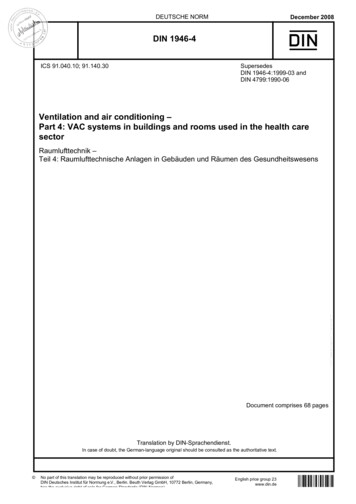
Local Exhaust Ventilation (LEV) GuidanceImproved hood effectivenessand efficiency through enclosure1600 cu.ft/min. (0.755m/sec.)(3 1205)3X(a) Capturing 100%150 cu.ft/min. (0.071m/sec.)312 (305) square openingX(b) Partial enclosure ( 10%)17 cu.ft/min. (0.008m/sec.)34 (102) squareopeningX(c) Total enclosure ( 1%) 22Chapter 4
Local Exhaust Ventilation (LEV) GuidanceImproving capture systems throughgood hood designChapter 423
Local Exhaust Ventilation (LEV) GuidanceEnclosuresPartial, smallRoomFullPartial, largeWhy does this airflow pattern matter?DOWN-FLOW ROOM/BOOTH24Chapter 4
Local Exhaust Ventilation (LEV) GuidanceDucting: This conducts air and the contaminant from the hood to the discharge point.Duct Design - Multiple branchesBranches should come into mainsoff the side if possible rather thanfrom underneathBendJunctionsMain ductBendSufficient inspectionports with easy accessBranchductsHorizontal ducting with adequate carrying velocity.Ducting of increasing size to accommodate increasing volume airflow.Chapter 425
Local Exhaust Ventilation (LEV) GuidanceThe ducting needs to be sized correctly to carry flow and should be oriented in such a way as toprevent turbulence. It must be of sound and solid construction (See previous chapter).Air cleaner or filter: This filters or cleans the extracted air. Not all systems need air cleaning.Air cleaner or filter types:TypeFiltering EfficiencyAdvantagesDisadvantagesFabric filterUp to 99.9%Efficiency increases as dustFlow resistancecake builds on fabric.increases with dustbuild-up. Abrasivescause wearCycloneDepends on particleEfficient for large particles.Less effective forsize.Minimum pressure drop.smaller particlesEffective in highHigh cost5µm particles – 50%8µm particles – 100%Electrostatic1to 50µm – 80 to 99%temperature and corrosiveprecipitator5 to 10µm – 99% conditions.Large equipmentRequires specialistmaintenanceWet scrubber 5µm – 96%1to 5µm 20 to 80%Effective with hot gases,corrosives. Eliminatesexplosion hazards.NoiseCorrosionBiological fouling(not an issue in causticor acid scrubbers)26Chapter 4
Local Exhaust Ventilation (LEV) GuidanceTypeFiltering EfficiencyAdvantagesDisadvantagesPacked towerHigh-level surfaceEffective for waterNoisescrubbercontact for reactionmiscible/soluble materialsCorrosionBiological fouling(not an issue in causticor acid scrubbers)Air cleanerFor gases or vapours(thermalEffective in destroyingNot suitable for solidsgases and vapours.oxidation,incinerationor flare)Voltage control boxCleanedair outDirtyair sChapter 427
Local Exhaust Ventilation (LEV) GuidanceClean air outletFan and motor assembly2m approxFabric fillerShaker motorCleanCleanedairair outDirty air inletDust storage inletDirtyairDirtyinairDirtyair swirlsDirtyair swirlsaroundaroundoutsideoutsideof chamber,throwingoff dustof chamber,throwing off dustDust falls intoDust fallshopperintocollectioncollection hopper28Chapter 4
Local Exhaust Ventilation (LEV) GuidanceAir mover: The fan is the most commonly used air mover that powers the extraction system.The fan can be of a number of types:1. Centrifugal – most commonly used for LEV system. Generates large pressure differences andproduces air flows against considerable resistance.2. Propeller – more often used for general ventilation and usually not suitable where there is pressureresistance, i.e. in-line filter.3. Axial – not suitable for dusts and cannot overcome pressure re
dust, fume, mist, in other words aerosols (hazardous agents), in the workplace air by using local exhaust ventilation (LEV), i.e. extracting the contaminant and preventing exposure. Cyan 100% Magenta 76% Yellow 0 Black 27% Local Exhaust Ventilation (LEV) Guidance 4 Chapter 2