Transcription
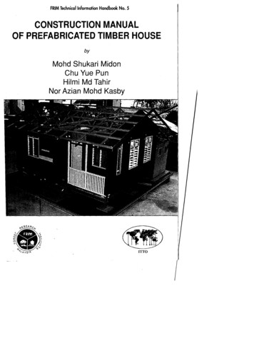
FRIM Technical Information Handbook No. 5CONSTRUCTION MANUALOF PREFABRICATED TIMBER HOUSEbyMohd Shukari MidonChu Vue PunHilmi Md TahirNor Azian Mohd KasbyITTO
-------- . ---------
FRIM Technical Information Handbook No. 5CONSTRUCTION MANUALOF PREFABRICATED TIMBER HOUSEbyMohd Shukari MidonChu Vue PunHilmi Md TahirNor Azian Mohd KasbyManual produced under the project"Research on the Utilization of Tropical Timber in Construction".An International Tropical Timber Organization (ITTO) funded projectcarried out at the Forest Research Institute Malaysia (FRIM).ITTOForest Research Institute Malaysia(FRIM)International Tropical TimberOrganisation1996
Forest Research Institute Malaysia (FRIM)1996Perpustakaan Negara Malaysia Cataloguing-in-Publication DataConstruction manual of prefabricated timber house I by Mohd.Shukari Midon . [et al.].(FRIM technical information handbook, ISSN 0127-9793; no. 5)ISBN 983-9592-55-61. Wooden-frame houses - Design and construction - Handbooks,manuals, etc. 2. Prefabricated houses - Design and construction Handbooks, manuals, etc. I. Mohd. Shukari Midon. 11. InstitutPenyelidikan Perhutanan Malaysia. Ill. Series.721.0448Editorial: Norani Ahmad & Nik Zanariah Nik MahmoodTypesetter: Zuriati Ahmadin
CONTENTSPREFACEACKNOWLEDGEMENTS1 INTRODUCTION, 12 FABRICATION SYSTEM, 2Pre-cut system, 1Modular panel system, 1Large size panel system, 2Volume element system, 43 DESIGN OF THE HOUSE,S4 BASIC PRINCIPLES, 8Sequence of construction, 115 GENERAL REQUIREMENTS AND SPECIFICATION OF MATERIAL, 13General requirement, 13Specification of material, 146 DETAILS OF CONSTRUCTION, 17Site access, 17Preparation of site, 17Setting out, 18Footings, 21Platform, 21Wall panels, 25Kitchen, 28Roof trusses, 30Doors and windows, 34Railings and stairs, 34Ceiling, 35Services, 37Finishing touches, 38
7 MAINTENANCE AND REPAIR, 39Raised platform, 39Exterior walls, 39Interior, 40Roof,40REFERENCES, 41APPENDIXAppendix I, Detailed Technical Drawings of the Whole House
PREFACEThis manual is the end product of the FRIM/ITTO project on "Research onUtilization of Tropical Timber in Construction". The project which was cqrriedout in FRIM was funded by ITTO together with some financial support fromPRIM. The aim of the project was to come up with a manual to illustrate theconstruction of a prefabricated 10w-cost' timber house.This manual is able to assist those who wish to build prefabricated timberhouses either mass-prod uced in a factory or as single uni ts. The type of housegiven in this manual is of the timber-framed type, based on the platformmethod. This manual attempts to show builders the good practice of producinghouses so that these houses can perform in a manner as expected of a goodtimber house. The fundamental principles of timber-framed housing are alsoexplained. These general principles are also applicable to other timber framemethods.The house as described in this manual is only a typical factory made timberframed house. Other arrangements of the house as regards to layout, height,size, etc. are possible and can be built using similar procedure and guidelinesas given in this manual.Beside describing the procedure in building the house, this manual also hasa chapter on the maintenance of the house after it has been built and is beingoccupied. A brief specification of the timbers and the types of materials usedin the construction of the house are also given.
ACKNOWLEDGEMENTSThe publication of this manual is made possible with the financial supportand assistance from the International Tropical Timber Organization (ITTO)through its funding for the project "Research on the Utilization of TropicalTimber in Construction" which was carried out in the Forest ResearchInstitute Malaysia (FRIM).We wish to record our thanks to Dr. Salleh Mohd. Nor. the formerDirector General, and Dr. Abdul Razak Mohd. Ali, the present ,Director Generalof FRIM for their encouragement, and the supporting staff for theirassistance throughout this project.
Chapter 1INTRODUCTIONThere are at present in Malaysia a number of factories making prefabricatedtimber houses using their own proprietary system of construction. The prefabricated house as proposed here is another method of construction where theparts of the house may be assembled in the factory or at the site in a do-ityourself manner. Since there are very few guides available on the constructionof timber houses, it is believed that a manual of this type illustrating suchconstruction would be useful to builders of timber houses.The aim of this manual is to recommend a system of construction not as aclose proprietary system but as a general method for all who are interested inthe use of timber.The system of prefabrication proposed in this manual is the result ofresearch carried out in FRIM on the structural strength of timber, timber joints,wall panels, roof trusses and the different components that made up the wholehouse. The system proposed here is the Modular Panel System.The house can be built individually or mass-produced in a factory since theyare of the prefabricated system. The step by step procedure in building thehouse as described herein is straight forward and easy to follow. There aremany illustrations or sketches in this manual and this would further help abuilder to comprehend what is described in the text. Not all the detaileddimensions of the various components are given in the text of this manual, butattempts are made to show the procedure and the sequence of construction.Detailed dimensions of the various components are given in the drawings of thehouse, in the Appendix.Although the house is primarily designed for use in Malaysia, it wouldalso be suitable for the building to be constructed in regions with similarclimates, except in places which have very strong winds or hurricanes.The arrangement of the house such as the partition of the rooms, hall, orother internal partitions can be altered to suit individual preferences withoutaffecting the structural strength of the house as a whole, since these partitionsare designed as non-load bearing walls.
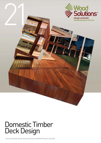
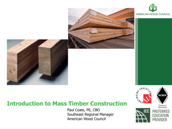
Chapter 2FABRICATION SYSTEMThere are a number of prefabrication systems in building a timber house. Thefollowing are some of them.Pre-cut systemThe pre-cut system is the oldest system of prefabrication. Pieces of timberare processed, cut to the required lengths, notched or drilled at the factory. Thepieces are then marked and transported to the site for assembly. Transportationof the pre-cut timber is simple because they can be bundled into units anddelivered to the building site. Compared to the conventional method of cuttingtimber in falling lengths at the site, this system is more accurate in its measurement and material wastage is minimised.Modular panel systemUnder the modular panel system, building components are constructed inthe factory by two or three men without the use of cranes or other liftingdevices. Wall panels are in uniform sizes using a module (M) as a unit ofmeasurement. The normal unit 'M' is 1.22 m (4 ft.) in length to tally with thesize of most cladding materials in Malaysia such as plywood, hardboard,chipboard and cement board. The mod ular panel system is the system adoptedin this manual (see Figure 1).
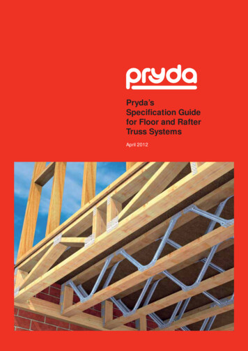
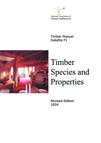
r :: -Roof trussCeiling paneljoistFigure 1. Modular panel systemLarge size panel systemThe large size panel system as shown in Figure 2, is suitable for use whenconstructing a large number of small houses at the same time. Large panels upto 10 to 12 m equalled to the length of adwelling can be assembled in thefactory and delivered to the building site for erection. The use of large sizepanels reduces the problem of joining together the small prefabricated panelssatisfactorily at the building site. However this advantage is offset by theincreased in transport and handling costs and the necessity of using cranes inlifting the large panels.
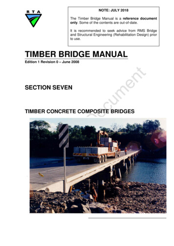
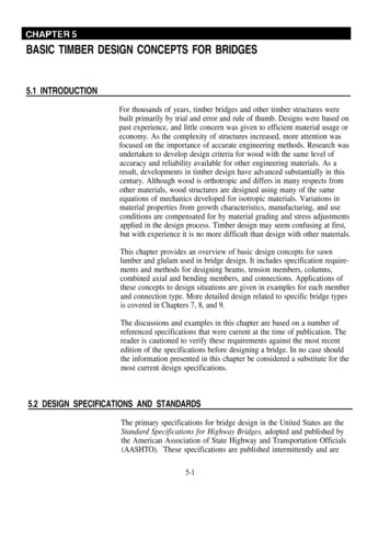
Roof trussFigure 2. Large size panel systemVolume element systemIn the volume element system of prefabricated housing, dwellings arecompletely finished at the factory. This system permits a home buyer to seeexactly what his house will look like before it is built. This method ofconstruction is very much faster than the other methods as far as site erectionis concerned, but it requires the use of trailers for transportation and cranes forerection (see Figure 3). ------Foundolion beamsFigure 3. Volume element systemA
Chapter 3DESIGN OF THE HOUSEThe traditional method of house construction in Malaysia is of the post andbeam structural form in which beams spaced widely apart (between 2 and 4 min domestic buildings) are supported on individual columns or posts to form askeletal structure. The non-load bearing infill panels will form the wall andwindow units between the columns.The house proposed in this manual is the timber-framed or wood-framedhouse and falls within the category of modular panel system as mentionedpreviously. The method of timber-framed house construction is traditional inNorth America, Scandinavia and some other parts of the world but is comparatively new in this country.Basically there are two methods of building a timber-framed house, theballoon frame and the platform frame method. The balloon frame method hasstuds running the full height of the building and the intermediate floor joists areside-fixed to the studs and supported from them. The system is only suitablefor either two or four storey buildings. In the more common platform framemethod the shell is built one storey at a time using storey height wall panels tosupport the intermediate floors, which are then used as a construction platformto erect the next storey or the roof above. The platform frame method is usedin this manual. These two framing methods are shown in Figures 4 and 5.In timber-framed housing, partitions or wall panels are assembled byhaving the top and bottom horizontal plates spaced at a distance apart to suitthe designed height of the building which in this case is 2.75 mm (9 ft.) high.Vertical studs at generally 0.16 m centres are then nailed to the top and bottomplates. Where necessary noggings are added in to strengthen the edges of theintended sheathings. Sheets are then fixed to the framework either on one sideonly or on both sides. For simplicity all the framework is assembled with buttjoints and fixed with nails. Figure 6 shows such a wall panel which is normallyprefabricated at the factory. For ease of man-handling, the pre-assembled wallpanels are made to a length not more than 3000 mm long. The wall panels arethen erected over the prepared platform and the roof is put over it to completethe building.
Stud full height01 buildingFigure 4. Balloon frame methodThe main advantages of the timber-framed system of construction are:(1)Transportation of pre-assembled panels is simple;(2)Less labour is required on site, even when the panels are made up onsite. If the panels are assembled at the factory, considerable saving inlabour are possible;(3)The pre-assembled wall panels can be erected manually by two orthree men without the use or cranes;(4)More speedy erection. It is possible to put up the whole timberframed wall panels of a house within two to three days. Once the roofis covered, other works such as plumbing and electrical services canbe started inside under assured dryness;(5)Houses can be finished at low cost to a high standard of thermalinsulation,(6)Flexibility in architectural design, modification and extension ispossible.
Figure 5. Platform frame method.1I\t".".Figure 6. Typical prefab wall panel
Chapter 4BASIC PRINCIPLESThe dimensioning of the house is based on a modular system which means thebest use is made of materials, especially sheet materials and also the house caneasily be extended at a later stage. Most sheet materials obtainable locally areof size 1220 x 2240 mm, therefore the planning of the house is based on the useof dimensions which are multiples of 610 mm. Hence a grid of 610 mm is usedin the plan layout as well as positioning in fixing of the partitions, roofs, joists,etc. These and an alternative future extension are shown in Figure 7. In themodular panel system, architects can design a wide variety of houses withmany different floor plans using prefabricated panels.extensIOnProposed4270rIwt:I-- c -!IKi .SII I III Is R2I Ii I !IIIIIILVDIIBR1VII I I732031II IiISRIIIIII1 1TI30 ;0Proposed houseWith extensionFigure 7. Plan of building on grid linesr. Grid tines610 mm crs.
Unlike the post and beam type of construction where the load is supportedby the post and beam, the timber-framed house has the wall panels supportingthe load which means the wall panels are made load bearing.In the arrangement of different components of the house, it is desirable thatroof trusses, studs in wall panels and floor joists are kept in line (see Figure 8)for efficient transferring of load from the roof to the ground via these members.In this proposed house, the spacing of the trussed rafter roofs is at 1220 mmcentres while those of studs and floor joists are at 610 mm centres.Roof truss @1220 erst-Roof trussr-;-H eadbinderTop plateNog.6 -Veri ieal studLint elCrip pie studDoor11,-/ M[XlMl Joists @610 erslXlBottom plateBase plateboardFloor joistBearerM-t- Floor/fFigure 8. Vertical alignment of roof, stud and joistl-
Wall panels can be of load bearing or non-load bearing walls type. Loadbearing walls are designed to support the floor and the roof above them. Nonload bearing walls do not support any load above them and they function aspartitions. They are therefore made shorter than the load bearing walls in thesame storey so that the roof or the floor joist above them does not rest on thesewalls as shown in Figure 9.Hon -loadwall bearingbearingFigure 9. Clearance for non-load bearing wallIf there is an opening in the wall panels such as for door or window, a lintelis required to span the opening. The ends of lintels are supported on extra studsknown as cripple studs which are fixed at each side of the door or windowopening as in Figure 8. For small openings, lintels are not necessary; they canbe fitted between studs and are simply framed up.The following sizes and tolerances must be observed in making wall panels:(1)Depth oftimber studs must be the same throughout, so thatthe widthof the finished panel with sheathings is the same. For example, if thestud is specified as 47 by 97 mm then the latter dimension must beaccurate or regularised.(2)A vertical gap of between 1 to 3 mm should be provided betweenplywood sheathings to allow for their expansion. The gap is thencovered up with beading.(3)The finished length of each completed prefabricated panel is to be 1to 3 mm less than the finished size as stated in drawing.The house may be built as a separate detached unit or linked to each otherby a separating wall as shown in Figure 10.
T r--pr-1.-/vV //SeparatinV //House 1idlinesJ05 mmwallVHouse 1//V //f' V/ / // / /V Vf//,305\,,'(mlnJFigure 10. Plan of separating wallsSequence of constructionThe proposed house is shown in plan view in Figure 7 and in perspective viewin Figure 11. The main building at frontal end is on a raised platform which is700 mm above the ground and the kitchen at the back is on ground level. Thetotal built-up area is 50 m 2 and the height of the building from floor to ceilingis a comfortable 2745 mm (9 ft.). The house can be enlarged in the future in adirection as shown in Figure 7.Figure 11. Perspective view of house
In the sequence of construction the ground is first prepared by layingconcrete footings. Posts are erected over the footing. Bearers are attachedacross the posts with bolts. Floor joists with stiffening across pieces are laid overthe bearers. Floor boards with tongue and groove are conceal-nailed to the joistsand the platform is now ready for the next stage of construction.Over the platform, pre-assembled wall panels are put up. During this timework can also start simultaneously in the kitchen which is on ground level andwhich is not connected to the platform at this stage. When the panels are erectedover the platform as well as over the kitchen, head binders or wall plates willthen bind the top of the panels together; and they also act as support for rooftrusses. The panels are also fixed firmly together sideways with nailed ironplates or angles, which are then concealed with beading.On top of the wall plates, prefabricated trussed rafter roofs are fixed. Therafters are braced diagonally and purlins are nailed over them. When roofingsheets have been laid, the dwelling is protected from rain and shine. Doors andwindows can now be installed. All other subsidiary works such as plumbing,electrical wiring and sanitation can be commenced.The house may now be painted and is ready for occupation.
Chapter 5GENERAL REQUIREMENTS ANDSPECIFICATION OF MATERIALGeneral requirementsThe general requirements for materials for the house are as follows:TimberTimber group:Strength Group B as given in the Malaysian StandardCode of Practice M.S.544 :1978 [SIRIM(2)].Timber grades:Standard structural grade in accordance with Part Ill,Section J MGR(3).Timber size:As given in drawing. Exposed surfaces shall be planed,unexposed surfaces sawn unless regularised, such asstuds size of 47 x 97 mm where the dimension of 97 mmis fixed.Moisture content:At time of installation, MIC of floor boards shall notexceed 18% and MIC of other timber shall not exceed22%.Treatment:Pressure impregmented with CCA to a dry salt retentionof 5.6 kg m-3 and the depth of penetration of CCA shallbe at least 12 mm.PlywoQdPlywood should be purchased from a reputable mill. It should be either ofthe water boil proof (WBP) type or of the moisture resistant (MR) type in therespective position as stated in the plan.
Cement-bonded particleboardCement-bonded particleboard for kitchen use should be obtained from areliable agent of the cemboard manufacturing factory. Fixing of cementbonded particleboard shall be in accordance with manufacturer's instructions.OthersAll other materials should be obtained and used in a manner consistent withgood construction practice.Specification of materialsThe specification and quantities.of materials as given in Table 1 are only asa guide. The detailed dimensions can be obtained from the technical drawings,in Appendix 1.Table 1. Specification and quantities of materialsItem NoPartMaterialSize (mm)RemarksPostBearerBearer spliceJoistJoist stiffenerTimber120 x 12060 x 19730x 19447x 145Top or conc. footingB/SofpostLengthen spliceTop of bearerSOx SOSOx 7522 x 14520x 19447x 11212.7 dia.6mm thick6mm thick12.7 dia.1:2:4 mix25 mm sizeAt end of joistAt mid joistT&GOose joist gapThicker panelJoint fastenerTo fix postBearer for postReinforcementFooting for postForconc.100 mm thick50 x 115SOx 8825 mm sizeWhole floorThicker panelThinner panelFor conc.(A) )FloorboardHeader joistBase plateBolts & nutsV-strapPlateRound barCone. footingHardcoreM.5.ConcreteStone(B) Kitchen floorBlB2FloorCurbConcreteB3HardcoreStone
(C) Wall panelsClC2C3C4CSC6C7C8C9CI0CllC12C13C14C15Studs (I)Timber(11)Untel (I)(11)Sheathing (I)Plywood(11)Sheathing (I)(II)Beading (I)(II)Pyrda nail plateangle 11Plate w /holesAngle plate w /hDowelCemboardPlywoodCemboardProductM.5.47x 9747x 7297x 14572 x 1459mmWBP6mmMR10mm8mm9mm8mm63x 8944x 44x9380x 8048 x48 x8012.7 dia.Thicker panelThinner"Thicker"Thinner "Outside surfaceInside"Kit. O/SKit. liSIn stripsConnection, flatcornerConnection, Cemb.Con. Cem. cornerEmbedded in curb(D) Head binderDlD2D3D4Platform (I)Timber47x 11222 x 8447x 11522 x 88Bind thick panel" thinBind thick panel" thinTimber35 x 7222 x 97Truss assemblyBrace trussFor ceilling boardB/S of truss jointto close end2' x 8' zigzagTop of trussAll round roof2 sizesAt peak(11)Kitchen (I)(II)(E) RoofingElE2E3E4E5E6E7E8E9ElORafter, tie, webBraceNoggingGusset plateGable endCeilingPurlinFascia boardRoofmg sheetRidge piece38x 509mmWBPPlywood"TimberFibrecem4mm MR35x7220x 1451830&2440Product(F) Door and windowFlF2F3F4F5F6F7F8F9Flush door (I)(11)(III)Window (I)Ply/timber0/ A 840 x 2100770 x 2100770 x 2100""Adj/fixed louv."(II)Window onlyFixed louv. (I)(11)(Ill)Adj.louv.Glass1055 x 1587414x 15871055 x 1213403 x 610440x 610700x 610Main entranceRoom / kitchenBath /WC7 off, platform1 off,loff,loff,1 off,1 off,
(G) Water TankGlWater adSupport stripAngle ironTimber7SOx 1220 x540 high4 /47 x 979mmWBPTop of bathTank supportTop of beam(H) Stairs (2 off)HIH2H3H460 x 21947x 2SOSOx SO63x 63 x 200Entrance & kit.2/3 treadsAttd. to stringLanding attachTimber47x 9720x 20Frame for meshTo rail and floorTimberProduct47x 97SOx SO crs.Frame for meshOose openingM.5.(I) Railing1112RailingBalustrade(J) Wire mesh in KitchenJlJ2FrameworkWire mesh1
Chapter 6DETAILS OF CONSTRUCTIONSite accessBefore construction begins, access to the site must be looked into, especially ifthe house is to be built in a remote area. If necessary an access road suitable forvehicles has to be constructed to transport construction materials to the site.Al though most of the component parts of the building are pre-assembled atthe factory, electric power and water supply are still required for many tasksduring the building process. Electric supply may be obtained from the supplymains or obtained from a generator. Water may be obtained from the watermains, well, river or transported to the site.At the plot, besides the area required for the proposed house, space for thestorage of prefabricated components and other building materials must beallocated away from building sites.Preparation of siteThe site of the house must be prepared first before construction work begins.The soil is examined to see whether it is suitable for the building. Since theproposed house is constructed of timber and is therefore light, most normalsoils would be suitable for its erection. If the place is known to be infested withtermi tes, an anti-termi te treatment is recommended for the soil before construction begins.The site should be cleared of all unwanted vegetation. During the processof grading, roots and other cellulosic materials should be removed, from thebuilding lot. Care must be taken to obtain adequate drainage of the area and inparticular of the building site. The frontal of the house may be built on levelground or on a gentle slope as this portion is of the raised platform type andhence the platform can be made level by adjusting the footing level or the lengthof the post (see Figure 12). The height of the floor must be at least 700 mm abovethe ground for effective ventilation. The site for the kitchen at the rear shouldbe made level by cu tting or filling earth with proper ramming to ensure theprepared surface is firm.17
(ilFooting adjustmentOatu i.!1i (!.!at-fo '-PostG.L(ii)PostadjustmentFigure 12. Platform on sloping groundSetting outWhen the site is prepared, the next step is to locate the house on the plot. Thehouse should not be built too close to the boundary to allow rooms for one tomove around the house with ease. Also if there is a house in the neighbouringplot, the empty space acts as firebreak. In Malaysia the minimum spacing isspecified in the Uniform Building By-laws, 1984 or the latest edition. If the plotis large enough building is located near one end of the plot to give allowance forfuture extension (see Figure 13).lR
Proposed buildingFutureextension////Figure 13. Position of building in plotWhen setting out the position of the platform, first mark on the plot theapproximate outline of the whole platform by driving in temporary pegs at thefour corners of the house where the footings are to be built.From the markings on the ground, set outthe corners of the house by puttingin batter boards. There are two batter boards at each corner, making it eight forthe four corners. The batter boards consists of two vertical stakes 50 mm x 100mm x approximately 1 m long driven into the ground. These stakes are fixedat a minimum distance of 1 m beyond the lines of corner foundation footings toavoid being disturbed during excavation (see Figure 14). A horizontal board of25 x 150 mm is then nailed to the vertical stakes. The tops of all horizontal batterboards are made the same level. This can be achieved by checking with asurveyor's level or by using a transparent hose filled with water as shown inFigure 15. The highest corner of the house is chosen as the datum batter boardwhere the levels of all other batter boards should follow.When the batter boards are in position, strings are then stretched tautbetween the boards. To indicate the positions of the strings in the batter board,a nail is driven or a saw kerf is made on the board so that the string may bereplaced if disturbed. Two adjoining sides of the building are first set using twosteel tapes. To check the squareness of the two sides, a third tape is used tomeasure the diagonal. The lengths of the two sides are 7230 mm and 5400 mm.The length of the diagonal is therefore equal to:Diagonal-J(723()2 540()2) 9096If the above length is too long, the squareness of the corners can also beachieved by using the common rule of "3-4-5" for a perfect 900 corner asshown in Figure 16. The sketch also shows the position of the first corner by
using a plumb bob and driving a nail into a stake underneath it. With the aboveprocedure, three corners of the house are fixed. The fourth corneris establishedin a similar way. Check the diagonals again to make sure all corners are square.Intermediate points of the footings are next marked using a steel tape andplumb bob. The measurements should always start from the corners and movealong the string. The ini tial settings of the stakes may be corrected now if theyare not accurate. The positions of all 12 footings are now set.Oiagonals equalCenlre line of foolingsFigure 14. Fixing outline of houseBoard to befixed hereOatum catter boaraTransparent plastIC Ii(f 3;,'( hose withwaterol,Figure 15. Leveling batter board
f',rst cor ner pointon groundFigure 16. Fixing one cornerFootingsThe strings can now be removed bu t the ba tter boards should be left in positionundisturbed, for further alignment and levelling.Excavate soil for the 12 footings at the positions marked on the ground. Thesize of each hole is 600 mm square and 400 mm deep. When the holes are ready,hardcore is placed into the holes and rammed properly up to 150 mm thick. Alevel of sand is put on top of the hardcore.Construct framework to hold the concrete. The minimum depth of concretefooting is 300 mm but may be of greater depth depending on the contour of theland If it is decided that the top surfaces of all concrete footings are of the samelevel. Top of concrete footing should be a minimum of 50 mm above the groundlevel. The other alternative is to vary the lengths of the posts over the footingsin which case the footing surfaces need not be of the same level. Before concreteis poured, reinforcement consistingof12 mm diameter Mild Steel (MS) bars areplaced near the bottom of each footing and MS V-strap for the posts are put atthe top of the footing. The V-straps must be properly aligned and levelled byusing strings between batter boards and plumb bobs as shown in Figure 12(0.Concrete can now be mixed. The proportion of the mix is 1 part cement, 2to 3 parts sand depending on its wetness and 4 parts stone. Mixing of concreteis preferably done using concrete mixer. If mixer is not available, mixing can beperformed manually but it must be done thoroughly until the whole mix isuniform. The mixed concrete is then poured into the prepared framework and'),
is then rodded or vibrated to achieve a dense concrete making sure the fixedreinforcement is not being disturbed.PlatformWhen the concrete footings are made, the next step is to fix the posts overthe footings. First put in MS bearing plates 120 x 120 x 6 mm thick within theV-strap and then put in the posts, each measuring 120 x 120 x 499 mm high. Fixthe bottom of each post to the V-strap with 2 bolts through holes previouslydrilled (Figure 17). ---BearerConc. looting - -.1/.7 x 19,Plate 110 x tl0 x GFigure 17. Joining details of post and bearerBearers can now be attached to the top of posts, one on each side with 4 boltsrunning through the 2 bearers and post. Washers are required for all bolt headsand nuts if they bear directly on the timber surface. The bearers are lengthenedby splice jpints at a place between the posts as shown in Figure 17. While fixingthe bearers, care should be taken to ensure the posts are truly vertical, the topof all bearers are horiwntal and of the same level.Floor joists are next placed on top of the bearers. They are fixed to the bearersby slant nailing using 75 mm nails, one on each side of the joist as shown inFigure 18. To stiffen the joists and to prevent them from tilting, stiffening cross?')
pieces 50 x 50 mm are placed at each end and 50 x 75 mm at the centre. Toaccommodate the cross pieces, notches are cut at the top ends of the joists.Figure 19 shows the joists being fixed in posi tion with the stiffening cross piecesembedded in the joists.Floor boards in the form of strip flooring 30 x 145 mm with tongue andgroove are next laid over the joists. Fit groove of one board to tongue of thematching board snugly and blind-nail through the tongue to the joist below asshown in Figure 20. A board or header joist 20 x 194 mm is fixed to the ends ofthe joist with its top level with the floor boards as shown in Figure 21. This boardwill conceal the empty spaces between the joists.JoistBearerFigure 18. Slant nailing of joist to bearer
earerEnd notch iorFigure 19. Attachment of cross piece to joistGroove ----TongueFigure 20. Concealed nailing of floor board
floor boardr &Gfloor iOISICross piece50 x 50Header 10iSl 10 x 19.JFigure 21.Floor bo
construction of a prefabricated 10w-cost' timber house. This manual is able to assist those who wish to build prefabricated timber houses either mass-prod uced in a factory or as single uni ts. The type of house given in this manual