Transcription
S IMULINK -S TATEFLOW T ECHNICAL E XAMPLESUsing Simulink and Stateflowin Automotive Applications AbstractTMThis book includes nine examples that represent typical design tasks of an automotive engineer. Itshows how The MathWorks modeling and simulation tools, Simulink and Stateflow, facilitateTMthe design of automotive control systems. Each example explains the principles of the physical situation, and presents the equations that represent the system. The examples show how to proceedfrom the physical equations to the Simulink block diagram. Once the Simulink model has beencompleted, we run the simulation, analyze the results, and draw conclusions from the study.
TABLEOFC ONTENTSIntroduction . 4System Models in Simulink. 7I. Engine Model. 8II. Anti-Lock Braking System. 18III. Clutch Engagement Model. 23IV. Suspension System. 31V. Hydraulic Systems . 35System Models in Simulink with Stateflow Enhancements . 49VI. Fault-Tolerant Fuel Control System . 50VII. Automatic Transmission Control. 61VIII. Electrohydraulic Servo Control . 71IX. Modeling Stick-Slip Friction . 84USING S IMULINK AND S TATEFLOWINA UTOMOTIVE A PPLICATIONS3
INTRODUCTIONSummaryAutomotive engineers have found simulation to be a vital tool in the timely and cost-effectivedevelopment of advanced control systems. As a design tool, Simulink has become the standard forexcellence through its flexible and accurate modeling and simulation capabilities. As a result of its openarchitecture, Simulink allows engineers to create custom block libraries so they can leverage each other’swork. By sharing a common set of tools and libraries, engineers can work together effectively withinindividual work groups and throughout the entire engineering department.In addition to the efficiencies achieved by Simulink, the design process can also benefit from Stateflow, aninteractive design tool that enables the modeling and simulation of complex reactive systems. Tightlyintegrated with Simulink, Stateflow allows engineers to design embedded control systems by giving theman efficient graphical technique to incorporate complex control and supervisory logic within theirSimulink models.This booklet describes nine automotive design examples that illustrate the strengths of Simulink andStateflow in accelerating and facilitating the design process.ExamplesDescriptionThe examples cited in this booklet consist of application design tasks typically encountered inthe automotive industry. We present a variety of detailed models including the underlyingequations, block diagrams, and simulation results. The material may serve as a starting point for thenew Simulink user or as a reference for the more experienced user. In the models, we propose approachesfor model development, present solutions to challenging problems, and illustrate some of the mostcommon design uses of Simulink and Stateflow today.The applications and models described in this booklet include the following examples using Simulinkalone:I.Engine Modelengine.mdl — open-loop simulationenginewc.mdl — closed-loop simulationII.Anti-Lock Braking Systemabsbrake.mdlIII.Clutch Engagement Modelclutch.mdlIV.Suspension Systemsuspn.mdlV.Hydraulic Systemshydcyl.mdl — Pump and actuator assemblyhydcyl4.mdl — Four-cylinder modelhydrod.mdl — Two-cylinder model with load constraints4S IMULINK -S TATEFLOW T ECHNICAL EXAMPLES
The following applications and models use Simulink enhanced with Stateflow:VI.Fault-Tolerant Fuel Control Systemfuelsys.mdlVII.Automatic Transmission Controlsf car.mdlVIII. Electrohydraulic Servo Controlsf electrohydraulic.mdlIX.Modeling Stick-Slip Frictionsf stickslip.mdlSimulinkModel FilesThe models used in this book are available via ftp s/autobook.zip. This zip file contains the setof MDL, MAT, and M-files containing Simulink models that users can explore and build upon. Theincluded files require MATLAB 5.1, Simulink 2.1, and Stateflow 1.0. Models for these applications can beopened in Simulink by typing the name of the model at the MATLAB command prompt. MATLAB,Simulink, and Stateflow are not included with this booklet. To obtain a copy of MATLAB, Simulink, andStateflow, or for a diskette containing the model files, please contact your representative at TheMathWorks.AcknowledgmentsThe engine model is based on published findings by Crossley and Cook (1991)(1). We’d like to thankKen Butts and Jeff Cook of the Ford Motor Company for permission to include this model and forsubsequent help in building the model in Simulink.The clutch and hydraulic cylinder models are based on equations provided by General Motors. We’d liketo thank Eric Gassenfeit of General Motors for permission to include these models.The vehicle suspension model was written by David MacClay of Cambridge Control Ltd.The simple three-state engine model and the set of icons that are relevant for automotive modeling wereprovided by Modular Systems. A far more detailed engine model may be purchased directly from ModularSystems.ContactInformationThe MathWorks technical personnel specializing in automotive solutions can be reached via e-mailat the following addresses:Stan Quinnsquinn@mathworks.comAndy Graceagrace@mathworks.comPaul Barnardpbarnard@mathworks.comLarry Michaelslmichaels@mathworks.comBill Aldrichbaldrich@mathworks.comUSING S IMULINK AND S TATEFLOWINA UTOMOTIVE A PPLICATIONS5
Or contact any of our international distributors and resellers directly. See the back page for additionalcontact information.Both Modular Systems and Cambridge Control Ltd. offer consulting services in automotive modeling.They can be reached as follows:Attention: Robert W. WeeksModular Systems714 Sheridan RoadEvanston, IL 60202-2502 USATel: 708-869-2023E-mail: bobweeks@ix.netcom.comAttention: Sham AhmedCambridge Control Ltd.Newton HouseCambridge Business ParkCowley RoadCambridge, DB4 4WZUK011/44-1223-423-2E-mail: Sham@camcontrol.co.uk6S IMULINK -S TATEFLOW T ECHNICAL EXAMPLES
System Models in SimulinkUSING S IMULINK AND S TATEFLOWINA UTOMOTIVE A PPLICATIONS7
I. ENGINE MODELSummaryThis example presents a model of a four-cylinder spark ignition engine and demonstrates Simulink’scapabilities to model an internal combustion engine from the throttle to the crankshaft output. We usedwell-defined physical principles supplemented, where appropriate, with empirical relationships thatdescribe the system’s dynamic behavior without introducing unnecessary complexity.OverviewThis example describes the concepts and details surrounding the creation of engine models with emphasison important Simulink modeling techniques. The basic model uses the enhanced capabilities ofSimulink 2 to capture time-based events with high fidelity. Within this simulation, a triggeredsubsystem models the transfer of the air-fuel mixture from the intake manifold to the cylinders viadiscrete valve events. This takes place concurrently with the continuous-time processes of intake flow,torque generation and acceleration. A second model adds an additional triggered subsystem that providesclosed-loop engine speed control via a throttle actuator.These models can be used as standalone engine simulations. Or, they can be used within a larger systemmodel, such as an integrated vehicle and powertrain simulation, in the development of a traction controlsystem.Model DescriptionThis model, based on published results by Crossley and Cook (1991), describes the simulation of a fourcylinder spark ignition internal combustion engine. The Crossley and Cook work also shows how asimulation based on this model was validated against dynamometer test data.The ensuing sections (listed below) analyze the key elements of the engine model that were identified byCrossley and Cook: Throttle Intake manifold Mass flow rate Compression stroke Torque generation and accelerationNote: Additional components can be added to the model to provide greater accuracy in simulation and tomore closely replicate the behavior of the system.Analysisand PhysicsTHROTTLEThe first element of the simulation is the throttle body. Here, the control input is the angle of the throttleplate. The rate at which the model introduces air into the intake manifold can be expressed as the productof two functions—one, an empirical function of the throttle plate angle only; and the other, a function ofthe atmospheric and manifold pressures. In cases of lower manifold pressure (greater vacuum), the flowrate through the throttle body is sonic and is only a function of the throttle angle. This model accounts for8S IMULINK -S TATEFLOW T ECHNICAL EXAMPLES
this low pressure behavior with a switching condition in the compressibility equations shown inEquation 1.1.m ai f (θ )g (Pm ) mass flow rate into manifold (g/s) where,f (θ ) 2.821 0.05231θ 0.10299θ 2 0.00063θ 3θ throttle angle (deg)Equation 1.1 PPm amb 1,2 P22amb Pm Pamb Pm , Pm Pamb 2g (Pm ) Pamb 22Pm Pamb Pamb , Pamb Pm 2Pamb P m 1,Pm 2Pamb Pm manifold pressure (bar)Pamb ambient (atmospheric) pressure (bar)Intake ManifoldThe simulation models the intake manifold as a differential equation for the manifold pressure. Thedifference in the incoming and outgoing mass flow rates represents the net rate of change of air mass withrespect to time. This quantity, according to the ideal gas law, is proportional to the time derivative of themanifold pressure. Note that, unlike the model of Crossley and Cook, 1991(1) (see also references 3through 5), this model doesn’t incorporate exhaust gas recirculation (EGR), although this can easily beadded.RTP m (m ai m ao )VmEquation 1.2where,R specific gas constantT temerature ( K)Vm manifold volume (m 3 )m ao mass flow rate of air out of the manifold (g/s)P m rate of change of manifold pressure (bar/s)Intake Mass Flow RateThe mass flow rate of air that the model pumps into the cylinders from the manifold is described inEquation 1.3 by an empirically derived equation. This mass rate is a function of the manifold pressureand the engine speed.2m ao 0.366 0.08979 NPm 0.0337NPm 0.0001N 2P mUSING S IMULINK AND S TATEFLOWINA UTOMOTIVE A PPLICATIONSEquation 1.39
where,N engine speed (rad/s)Pm manifold pressure (bar)To determine the total air charge pumped into the cylinders, the simulation integrates the mass flow ratefrom the intake manifold and samples it at the end of each intake stroke event. This determines the totalair mass that is present in each cylinder after the intake stroke and before compression.Compression StrokeIn an inline four-cylinder four-stroke engine, 180 of crankshaft revolution separate the ignition of eachsuccessive cylinder. This results in each cylinder firing on every other crank revolution. In this model,the intake, compression, combustion, and exhaust strokes occur simultaneously (at any given time, onecylinder is in each phase). To account for compression, the combustion of each intake charge is delayedby 180 of crank rotation from the end of the intake stroke.Torque Generation and AccelerationThe final element of the simulation describes the torque developed by the engine. An empiricalrelationship dependent upon the mass of the air charge, the air/fuel mixture ratio, the spark advance, andthe engine speed is used for the torque computation.Torque eng 181.3 379.36 m a 21.91( A / F ) 0.85( A / F ) 2 0.26σ 0.0028σ 2 0.027N 0.000107N 2 0.00048Nσ 2.55σm a 0.05σ 2 m aEquation 1.4where,ma mass of air in cylinder for combustion (g)A / F air to fuel ratioσ spark advance (degrees before top - dead - centerTorqueeng torque produced by the engine (Nm)The engine torque less the net load torque results in acceleration.JN Torqueeng TorqueloadEquation 1.5where,J Engine rotational moment of inertia (kg-m2)Ṅ Engine acceleration (rad/s2)10S IMULINK -S TATEFLOW T ECHNICAL EXAMPLES
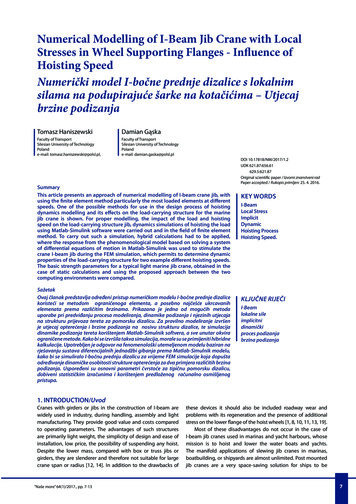
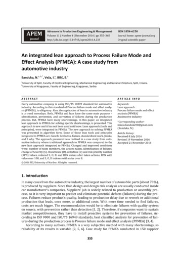
Modeling —The Open-LoopSimulationWe incorporated the model elements described above into an engine model using Simulink. Thefollowing sections describe the decisions we made for this implementation and the key Simulink elementsused. This section shows how to implement a complex nonlinear engine model easily and quickly in theSimulink environment. We developed this model in conjunction with Ken Butts, Ford Motor Company (2).Figure 1.1 shows the top level of the Simulink model. Note that, in general, the major blocks correspondto the high-level list of functions given in the model description in the preceding summary. Takingadvantage of Simulink’s hierarchical modeling capabilities, most of the blocks in Figure 1.1 are made upof smaller blocks. The following paragraphs describe these smaller blocks.Engine Timing Model in Simulink 2A Demonstration of Triggered Subsystemschoose Start fromthe Simulationmenu to runedge1801Ncrank speed(rad/sec)valve timingmass(k)Air ChargeTorquemass(k 1)Throttle Ang.triggerthrottle(degrees
Acknowledgments The engine model is based on published findings by Crossley and Cook (1991)(1). We’d like to thank Ken Butts and Jeff Cook of the Ford Motor Company for permission to include this model and for subsequent help in building the model in Simulink. The clutch and hydraulic cylinder models are based on equations provided by General .