Transcription
AN0816: EFM32 Brushless DC MotorControlThis application note shows how to drive a brushless dc (BLDC)motor with an EFM32 device. It includes firmware for a BLDCcontroller and a GUI tool to monitor and control the motor. BothHall-sensor and sensorless control are supported.The firmware is written to run on an EFM32GG-DK3750 or EFM32HG-SLSTK3400Aboard connected to the C8051F850 Motor Control Reference Design Board describedin detail in AN794: C8051F850 BLDC Reference Design Kit.KEY POINTS An EFM32 can be used to drive brushlessdc motors. This application note includes: This PDF document Source files (zip) Example C code Multiple IDE projectsBANSCsilabs.com Building a more connected world.Rev. 1.1
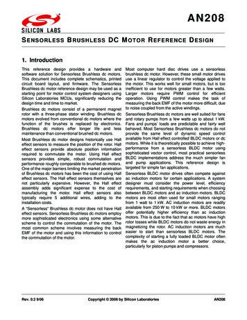
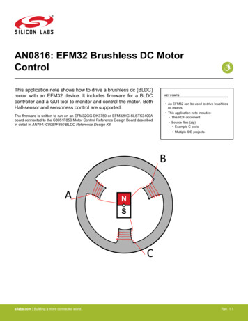
AN0816: EFM32 Brushless DC Motor ControlMotor Operation1. Motor OperationA brushless dc (BLDC) motor consists of a permanent magnet rotor and stator windings that are driven by an electric circuit. The following figure shows a simple view of a BLDC motor. In the figure, the central permanent magnet rotor is connected to a shaft and canmove in response to the magnetic fields set up by the stator windings. The rotor can also be on the outside with the stator windingspointing radially outwards. The permanent magnet in the following figure has two poles (1 pole pair), but a typical BLDC can have rotorswith several pole pairs.BANSCFigure 1.1. Brushless DC MotorA BLDC motor has three terminals, normally labelled A, B and C. The terminals are connected to the stator windings in either a delta orY configuration, see the following figure. In both configurations the motor is driven the same way. The rotor is moved by driving two ofthe terminals, which will cause the rotor to align with the magnetic field set up by the stator coils. When the controller continuouslychanges which terminals are driven the motor will rotate along with the field. A BLDC is similar to a stepper motor, but the difference isthat while the stepper motor is designed for small accurate steps and high holding torque, a BLDC is designed to run faster and providehigh torque at higher speeds.The process of switching which terminals are driven is called commutation. This is similar to a brushed motor, where commutation isdone mechanically by the brushes connecting to different coils as the motor rotates.silabs.com Building a more connected world.Rev. 1.1 1
AN0816: EFM32 Brushless DC Motor ControlMotor OperationAACBa) wye configurationCBb) delta configurationFigure 1.2. Winding ConfigurationsThe motor terminals are driven by a three-stage inverter circuit shown in the following figure and each stage is connected to one of themotor terminals. Each stage of the inverter can drive the terminal voltage to the high or low side of the motor supply. When the low-sidetransistor of one stage is conducting, the terminal is driven low. When the high-side transistor is conducting the terminal is driven high.QAHQBHAQALQBLQCHBCQCLFigure 1.3. Inverter CircuitThe inverter circuit repeatedly goes through 6 different commutation steps, see the following table, which forms one electrical revolution. Note that one mechanical revolution requires multiple electrical revolutions if the permanent magnet rotor has more than one polepair. The number of electrical revolutions per mechanical revolution is equal to the number of pole pairs of the motor.silabs.com Building a more connected world.Rev. 1.1 2
AN0816: EFM32 Brushless DC Motor ControlMotor OperationMechanical and Electrical Revolutionsωel np ωmechanicalTable 1.1. Commutation SequencePhaseAHBHCHALBLCLOpen1 (0 - 60 )onoffoffoffonoffC2 (60 - 120 )onoffoffoffoffonB3 (120 - 180 )offonoffoffoffonA4 (180 - 240 )offonoffonoffoffC5 (240 - 300 )offoffononoffoffB6 (300 - 360 )offoffonoffonoffAsilabs.com Building a more connected world.Rev. 1.1 3
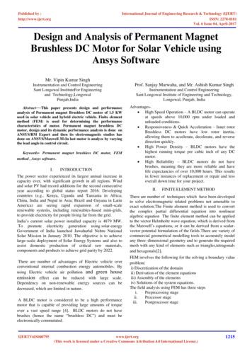
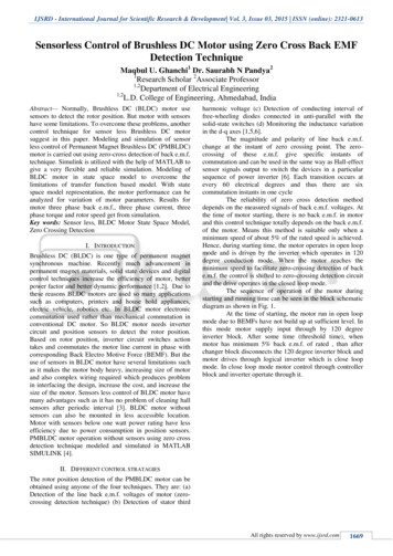
AN0816: EFM32 Brushless DC Motor ControlDetermining Rotor Position2. Determining Rotor PositionIn order to drive the motor, the controller needs information about the current position of the rotor. More specifically, the controllerneeds to know at which point to switch to the next phase. Commutating at the correct time ensures that the maximum amount of energyis transferred to the motor. Commutating incorrectly reduces the efficiency of the motor and will apply a breaking effect and can evenmake the motor spin in the wrong direction. The optimal commutation point is when the rotor is positioned such that it is exactly halfway between any of the permanent magnet poles crossing a stator coil.There are two popular methods for determining the correct commutation instant. The first is the use of Hall effect sensors to get therotor position. Using Hall effect sensors is the simplest and most accurate method, but it comes with an extra cost since three Hallsensors are needed per motor.For many applications, the Hall effect sensors are not strictly needed and it is quite common to get rid of these sensors and instead relyon measuring the back-EMF voltage in the open (undriven) terminal to determine the commutation instant. This method is often calledsensorless commutation.One el. cycle (360 )1Hall2330 CommutationAEMFZCPBCFigure 2.1. Hall Sensor Output and Back-EMF Voltage2.1 Hall Effect SensorsHall effect sensors can measure the presence of a magnetic field. When using Hall effect sensors with a BLDC, three sensors areplaced to cover 180 electrical degrees each, but with a 120 degrees phase shift between them. Reading the state of the three sensorsare enough to decode the current phase (1-6) of the rotor for any orientation.The commutation algorithm becomes very simple when using hall sensors. The optimal commutation points are exactly where the hallsensors change state. A GPIO interrupt is therefore enough to get the correct timing for each commutation. If the spinning direction isreversed, the Hall waveform in Figure 2.1 Hall Sensor Output and Back-EMF Voltage on page 4 is shifted 180 with respect to theterminal voltages.2.2 Sensorless Commutation / Back-EMF MeasurementsIn any phase, two of the terminals are driven, while the third is open. As the permanent magnet passes by the open winding a voltage isinduced, commonly referred to as the back-EMF. This voltage will either be rising or falling as the rotor moves, depending on whether asouth or north pole is passing by. The Zero Crossing Point (ZCP) is when the magnet is directly adjacent to the stator winding. At thispoint the voltage at the terminal is the same as the motor neutral voltage, V N.silabs.com Building a more connected world.Rev. 1.1 4
AN0816: EFM32 Brushless DC Motor ControlDetermining Rotor PositionZero Crossing PointVA – VN 0As can be seen from Figure 2.1 Hall Sensor Output and Back-EMF Voltage on page 4 the commutation instant is 30 after the ZCP.The algorithm to commutate with back-EMF measurements must first detect the ZCP, wait 30 and then switch to the next phase. The30 offset can be determined by keeping track of the current speed and using a timer to trigger the commutation at a speed-adjustedtime after each ZCP. The equation below gives the condition for a commutation event where t is the current time, tZCP is the last zerocrossing point and Tel is the period of one electrical revolution.Commutation Point with ZCPT el30 t – tZCP T 360 el 12One problem with this method is that the neutral point is not directly accessible since it is inside the motor. This can be solved by creating a "virtual neutral point" combined by the voltage at all three terminals, see the figure below.MotorRYLMRMeC RYLMRMLMRMVYRYVAVBeB -VNeA -VCFigure 2.2. Virtual Neutral CircuitZCP using Virtual Neutral PointV A – VY 02.3 StartupWhen the motor is starting up from a rest state, there is no measurable back-EMF. Therefore the motor must be driven like a steppermotor until it reaches sufficient speed. Each phase is activated in turn and the commutation speed is slowly increased until the speed ishigh enough to switch to back-EMF based commutation. Since the position of the rotor is unknown when starting the motor, it is possible that the motor will move backwards before it starts moving in the forward direction.The increase in speed must not be too fast or the motor will not be able to keep up. In this application note the time between commutation events is decreased so that the angular speed is increasing linearly. See AN794: C8051F850 BLDC Reference Design Kit for moreinformation. Each commutation time Tk is calculated by:Startup Commutation Intervalsk–1 Tii 0T k 1 T k k Tii 0If hall sensors are used, they give the position of the rotor even when it is at rest. Starting a motor with hall sensors is much simpler.The controller can simply read the rotor position and keep moving to the next phase.silabs.com Building a more connected world.Rev. 1.1 5
AN0816: EFM32 Brushless DC Motor ControlSpeed Control3. Speed ControlThe speed of a BLDC motor is proportional to the voltage (for a given load). Instead of modulating the voltage directly a Pulse WidthModulated (PWM) waveform is often used. The PWM can be applied to the top, bottom or both transistors. In this application note onlytop-side PWM is used. The top transistors are fed a PWM waveform while the bottom transistors are turned on/off. A complementaryPWM waveform is applied to the bottom transistor of the PWM fed stage to improve the performance.The controller needs a way to get the current speed of the motor and a control loop to adjust the setpoint accordingly. In this applicationnote, the speed is determined by measuring the time between commutation events and a PID controller is implemented.silabs.com Building a more connected world.Rev. 1.1 6
AN0816: EFM32 Brushless DC Motor ControlSpeed Control3.1 Complementary PWM with Dead-Time InsertionDuring the PWM on period, current flows through the upper transistor of one inverter stage, through the motor windings and finallythrough the lower transistor of another inverter stage, see the following figure, part (a). At the start of the PWM off period, the inductance in the motor windings will cause the current to keep flowing. Most of this current will go through the body diode of the first invertorstage, see the following figure, part (b). This recirculation current will decay and eventually reach zero if the PWM period is longenough.QAHQBHQCHBAQAHCMiQALQCHBACMQBHiQBLQCLa) PWM ON phase. Current flowing throughhigh side of one stage, the motor and bottomside transistor of second stage.QALQBLQCLb) PWM OFF phase. Recirculation currentthrough body diode of first stage, the motorand bottom side transistor of second stage.Figure 3.1. Current Flow in PWM ON/OFF PhasesThe recirculation current will cause heat buildup when flowing through the transistor body diode. It also reduces the performance of thePID controller, especially when braking since the controller has less control over the current through the motor. The recirculation currentalso reduces the accuracy of the ZCP since it creates an offset voltage at the motor terminal.In order to reduce the impact of the recirculation current, the bottom transistor of the first inverter stage can be turned on during thePWM off phase. I.e. the bottom transistors are being fed a complementary PWM signal to the top transistors. The recirculation currentgoes through the channel of the bottom transistor instead of the body diode. Heat dissipation is reduced and the recirculation currentdecays to zero quickly.silabs.com Building a more connected world.Rev. 1.1 7
AN0816: EFM32 Brushless DC Motor ControlSpeed ControlPhase123546AHBHNormal PWMCHComplementary PWMALBLCLFigure 3.2. Complementary High-Side PWM WaveformsWith a complementary PWM scheme, it is necessary with some dead time between the two PWM signals. The reason is that the transistors do not turn off instantly, but do have some response time before they switch on/off. If no dead time is inserted there could be ashort time every PWM cycle where both transistors in the same stage are ON and the circuit would effectively short the power supply toground.AHDead timeDead timeALFigure 3.3. Complementary PWM with Dead Time3.2 PID ControllerIn order to control the speed of the motor, a control loop is needed. In this application note a PID controller is implemented. A PIDcontroller tries to correct the error in the measured speed against a setpoint by adjusting the input (PWM) to the motor.A PID controller has 3 parameters: Kp – proportional gain Ki – integral gain Kd – derivative gainThe correction is calculated by:silabs.com Building a more connected world.Rev. 1.1 8
AN0816: EFM32 Brushless DC Motor ControlSpeed ControlPID Equationτdu(t) K p e(t) K i e(t)dτ K d e(t)dt0where e(t) is the error at time t.silabs.com Building a more connected world.Rev. 1.1 9
AN0816: EFM32 Brushless DC Motor ControlApplication Overview4. Application OverviewIncluded in this application note is firmware for running a BLDC controller on an EFM32 MCU. The code is intended for running on aEFM32GG-DK3750 Development Kit or EFM32HG-SLSTK3400A Starter Kit connected to a C8051F850 Motor Control Reference Design Board, discussed in detail in AN794: C8051F850 BLDC Reference Design Kit.silabs.com Building a more connected world.Rev. 1.1 10
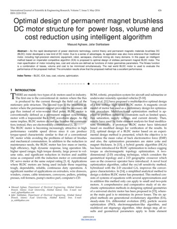
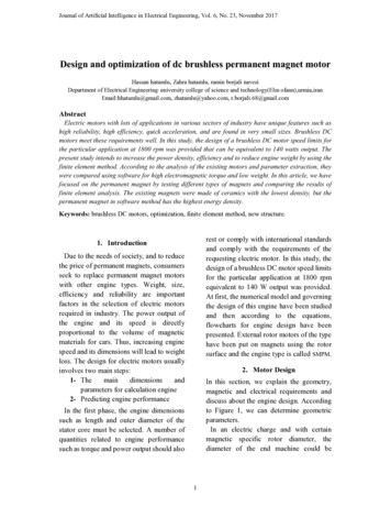
AN0816: EFM32 Brushless DC Motor ControlApplication Overview4.1 BLCD Reference DesignThe Silicon Labs C8051F850 Motor Control Reference Design Board is a ready-to-use hardware platform for developing BLDC motorcontrol applications. It comes with a C8051F850 MCU plugin board and firmware for the C8051F850. See AN794: C8051F850 BLDCReference Design Kit for a full description of the board and schematics. The reference design consists of three parts: a C8051F850MCU plugin board, the powertrain board and a BLDC motor.Figure 4.1. C8051F850 Motor Control Reference Design BoardThe EFM32 MCU is connected directly to the powertrain board. The C8501F850 MCU Plugin Board should be disconnected and astandard 0.1" pitch header soldered on to the 1x22 header footprint. The following table shows how to connect the MCU to the powertrain board.Table 4.1. Motor ConnectionFunctionPowertrainEFM32GG DK3750/MCUEFM32HG SLSTK3400A/MCUQ AH EnablePWM0APA0PF0Q BH EnablePWM1APA1PF1Q CH EnablePWM2APA2PF2Q AL EnablePWM0BPA3PF3Q BL EnablePWM1BPA4PF4Q CLPWM2BPA5PF5V A Terminal VoltageVMAPC1PC0V B Terminal VoltageVMBPC6PC1V C Terminal VoltageVMCPC7PC2V Y Virtual NeutralVMYPC0PC4Current sense resistor IM 0PPD6PD6Current sense resistor -IM 0NPD7PD7N/APB0N/AHall Sensor 11silabs.com Building a more connected world.Rev. 1.1 11
AN0816: EFM32 Brushless DC Motor ControlApplication OverviewFunctionPowertrainEFM32GG DK3750/MCUEFM32HG SLSTK3400A/MCUHall Sensor 21N/APB1N/AHall Sensor 31N/APB2N/AHall Sensor VDD1N/APB3N/AGate Drive EnableGDx ENGNDGNDNote:1. Optional. Only if using hall sensors.4.2 BLDC Controller FirmwareThe included firmware enables simple control of a BLDC motor. Both sensorless and hall sensor driven motors are possible.The motor is controlle with the buttons PB0/PB1 on the EFM32HG-SLSTK3400A. PB0 – Stop the motor or change direction: If the motor is stopped, this button changes direction. If the motor is running, this button stops the motor. PB1 – Start the motor or adjust speed: If the motor is stopped, this button starts the motor. If the motor is running, a long press of this button will decrease the speed of the motor, and a short press of this button will increase the speed of the motor.The motor is controlled with the buttons PB1/PB2 on the EFM32GG-DK3750. PB1 – Stop the motor or change direction: If the motor is stopped, this button changes direction. If the motor is running, this button stops the motor. PB2 – Start the motor or adjust speed: If the motor is stopped, this button starts the motor. If the motor is running, a long press of this button will decrease the speed of the motor, and a short press of this button will increase the speed of the motor.4.2.1 ConfigurationConfiguration is done at compile time in config.h. If another motor is used, the MOTOR POLE PAIRS must be updated to reflect thenumber of pole pairs. Here it is possible to change between sensorless or hall driven commutation or enable/disable the use of complementary PWM. A few other timing parameters can also be changed here. See the comments in config.h for details.4.2.2 EFM32 ResourcesThe controller uses three TIMERs. TIMER0 is used to generate PWM with DTI for the inverter control. The overflow interrupt on TIMER0 is also used to invoke the PID routine. TIMER1 is used to measure the time between commutations and thereby calculating themotor speed. TIMER2 is used to synchronize the ACMP and ADC measurement with the PWM waveform (if they are used).The ACMP is used in sensorless mode to measure the ZCP. The ACMP is triggered at the same point in the PWM waveform by theCC1 interrupt on TIMER2.The ADC is (optionally) used to measure the motor current by measuring the voltage across a current sense resistor in series with theinverter circuit. The ADC measurement is triggered half-way in the PWM 'ON' by TIMER2 through a PRS channel. If an overcurrentcondition is met (the measured current is higher than the configured maximum) the motor will stop. The motor current can also be logged to the PC tool for monitoring.UART1 of EFM32GG Giant Gecko or UART1 of EFM32HG Happy Gecko is used for logging and control with the PC tool. UART1 isconnected to the on-board RS-232 connector on the EFM32GG-DK3750. USART1 can be connected to the expansion header of theEFM32HG-SLSTK3400.silabs.com Building a more connected world.Rev. 1.1 12
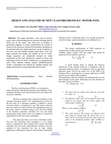
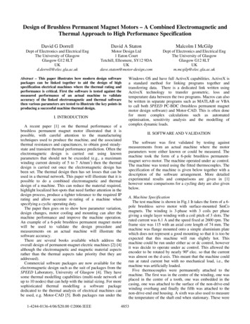
AN0816: EFM32 Brushless DC Motor ControlApplication Overview4.3 PC ToolA PC tool to log the response and control the motor is included. The efm32 bldc.exe is found in the application note directory. It canplot the speed, PWM and current draw while the motor is running. There are also controls to to start/stop the motor and set the PIDcoefficients and setpoint.The PC tool communicates with the MCU over UART, so a USB-to-UART adapter is needed. For EFM32GG Giant Gecko, connecteither a USB-RS232 cable to the RS232 port on the EFM32GG-DK3750 or use a USB-to-TTL-UART and connect this to PB9/PB10(MCU TX/RX). For EFM32HG Happy Gecko, use a USB-to-TTL-UART and connect this to PE10/PE11 (MCU TX/RX). The baud ratemust match the configuration in config.h.Figure 4.2. BLDC Control/Logging PC Toolsilabs.com Building a more connected world.Rev. 1.1 13
AN0816: EFM32 Brushless DC Motor ControlReferences5. ReferencesSee the following documents for more information:1. AN794: C8051F850 BLDC Reference Design Kit — This document contains detailed descriptions of the motor control board and itsoperation, including schematics.silabs.com Building a more connected world.Rev. 1.1 14
AN0816: EFM32 Brushless DC Motor ControlRevision History6. Revision History6.1 Revision 1.12017-03-08Updated formatting.Added support for EFM32HG.6.2 Revision 1.002014-05-23Initial revision.silabs.com Building a more connected world.Rev. 1.1 15
Simplicity StudioOne-click access to MCU andwireless tools, documentation,software, source code libraries &more. Available for Windows,Mac and Linux!IoT plicityQualitywww.silabs.com/qualitySupport and Communitycommunity.silabs.comDisclaimerSilicon Labs intends to provide customers with the latest, accurate, and in-depth documentation of all peripherals and modules available for system and software implementers using orintending to use the Silicon Labs products. Characterization data, available modules and peripherals, memory sizes and memory addresses refer to each specific device, and "Typical"parameters provided can and do vary in different applications. Application examples described herein are for illustrative purposes only. Silicon Labs reserves the right to make changeswithout further notice and limitation to product information, specifications, and descriptions herein, and does not give warranties as to the accuracy or completeness of the includedinformation. Silicon Labs shall have no liability for the consequences of use of the information supplied herein. This document does not imply or express copyright licenses grantedhereunder to design or fabricate any integrated circuits. The products are not designed or authorized to be used within any Life Support System without the specific written consent ofSilicon Labs. A "Life Support System" is any product or system intended to support or sustain life and/or health, which, if it fails, can be reasonably expected to result in significant personalinjury or death. Silicon Labs products are not designed or authorized for military applications. Silicon Labs products shall under no circumstances be used in weapons of massdestruction including (but not limited to) nuclear, biological or chemical weapons, or missiles capable of delivering such weapons.Trademark InformationSilicon Laboratories Inc. , Silicon Laboratories , Silicon Labs , SiLabs and the Silicon Labs logo , Bluegiga , Bluegiga Logo , Clockbuilder , CMEMS , DSPLL , EFM , EFM32 ,EFR, Ember , Energy Micro, Energy Micro logo and combinations thereof, "the world’s most energy friendly microcontrollers", Ember , EZLink , EZRadio , EZRadioPRO ,Gecko , ISOmodem , Precision32 , ProSLIC , Simplicity Studio , SiPHY , Telegesis, the Telegesis Logo , USBXpress and others are trademarks or registered trademarks of SiliconLabs. ARM, CORTEX, Cortex-M3 and THUMB are trademarks or registered trademarks of ARM Holdings. Keil is a registered trademark of ARM Limited. All other products or brandnames mentioned herein are trademarks of their respective holders.Silicon Laboratories Inc.400 West Cesar ChavezAustin, TX 78701USAhttp://www.silabs.com
1. Motor Operation A brushless dc (BLDC) motor consists of a permanent magnet rotor and stator windings that are driven by an electric circuit. The follow-ing figure shows a simple view of a BLDC motor. In the figure, the central permanent magnet rotor is connected to a shaft and can move in