Transcription
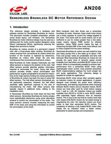
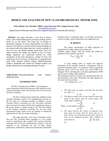
SPEEDAM 2008International Symposium on Power Electronics,Electrical Drives, Automation and MotionVector Control versus Brushless DCOperation of a Higher Harmonic AirgapWave Based Permanent Magnet MotorC. GrabnerResearch and Development Drive Systems, Siemens AGFrauenauracherstrasse 80, 91056 Erlangen, Germanygrabner.christian@siemens.comI.Abstract — The considered converter-fed permanent magnet motor could alternatively be operatedin two basically different states the vectorcontrol mode or alternatively the brushless dcalso known as electronically commutated mode.Several quality aspects concerning the system performance have been comparatively investigated inpractical as well as theoretical manner. Focus isthereby given to the numerical analysis and previous evaluation of the well interaction betweenthe novel axially un-skewed higher harmonic airgap wave based permanent magnet motor designand both completely different control algorithms.A straightforward industrial development process of electrical variable speed drive systems isfortunately assisted by modern commercial calculation tools [1-3]. However, the extensive and almost precise analysis of the interaction of different control algorithms, like the vector control orthe brushless DC mode, within introduced innovative permanent magnet motor topologies, ase.g. the higher harmonic air-gap based design, isstill a big challenge [4-6]. Several simplificationshave to be done in order to treat the analysis in areasonable way. The implemented main softwarefeatures, the interacting converter hardware andthe motor itself are almost analyzed in the timedomain. By using the same motor design, a comparative evaluation of the drive performance due todifferent control modes could be achieved.Index Terms — Vector control; brushless dc drive;electronically commutation; higher harmonic airgap wave; integrated circuit; drive control; finiteelement analysis with coupled circuit.dc linkdc to ac power converterT1T2INTRODUCTIONenergy rentmeasuringPWM-interfacegate oninterfaceinterfaceFEPROMFigure 1. Outline of important devices of the considered drive system.978-1-4244-1664-6/08/ 25.00 2008 IEEE1
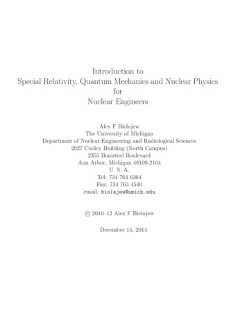
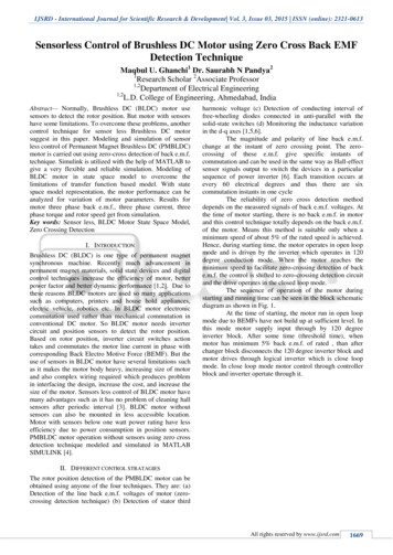
II.A. Design of the permanent magnet rotorObviously a number of p 14 magnetic polepairs are generated along the circumferential airgap direction. Favorably, the high pole numberallows a very thin yoke construction. The invokeddistribution of the magnetic field due to permanent magnet excitation is shown in Fig.2. Theseries space expansion of the radial flux densitycomponent Br (ϕ) along the circumferential airgap distance in accordance to ˆ sin k ϕ α Br (ϕ) B(1)kk 2π k 0REALIZED DRIVE SYSTEMThe investigated drive system is made up ofmany different hardware components [7-9]. Theessential internal interaction between the supplydc-link, the dc to ac power converter, the motor,the sensor, the controllers and communicatingtasks is schematically depicted in Fig.1. Thepower conversion from the constant dc voltagelink level to the ac voltage system at the motor iselementary performed by the PWM technology.The motor construction itself is built up for amechanical torque of approximately 1.35 Nm. Therotating shaft is assisted with a speed sensorwhich measures the actual position. Dependingon the control mode, an encoder or Hall-sensor isused. The main current and speed control algorithm for a stable operational behavior is implemented in the processor.III.yields several harmonic coefficients B̂k , k »with some distinct contributions, as it is obviousfrom Fig.3. The fourteenth component in the noload spectrum B̂14 0.91T acts thereby as thefundamental air-gap wave of the drive.B. Innovative stator design invoking higherharmonicsIn order to generate the same number of p 14rotor pole pairs, a fourteenth harmonic wave inthe circumferential air gap flux density distribution has to be generated from the stator currentexcitation. This is advantageously done by theestablished alternating thin and thick toothstructure along the circumferential air gap. Thenumerically calculated distribution of the magnetic field due to the stator current excitation onlyis shown in Fig.4.HIGHER HARMONIC AIR-GAP WAVE BASEDPERMANENT MAGNET MOTOR DESIGNThe moving rotor with attached permanentmagnets is almost characterized by its even number of involved magnetic poles, whereas the fixednovel stator winding design comprises the samepole number by means of higher space harmonics[10]. Both, stator and rotor designs are therebyunskewed.Figure 4. Constant magnetic vector potential lines in case ofstator current injection for the range 0.002 Vs/m.1,01,00,90,90,80,8radial airgap flux density [T]radial airgap flux density [T]Figure 2. Constant magnetic vector potential lines at no-loadfor the range 0.002 c order [1]harmonic order [1]Figure 5. Fourier spectrum B̂k of the radial flux densitycomponent at default stator current.Figure 3. Fourier spectrum B̂k of the radial flux density component at no-load.2
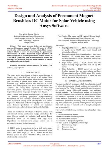
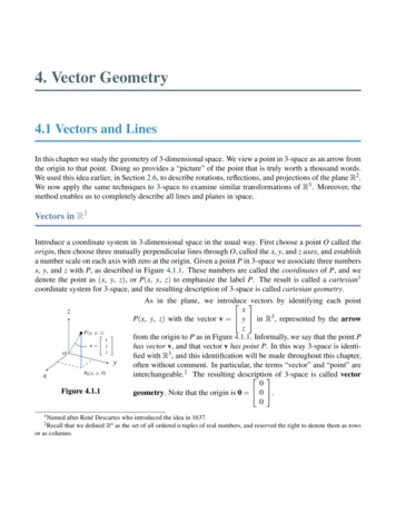
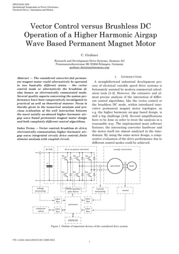
u q (τ) uSq (τ) ωlS iSd (τ) ωψ M From the series expansion (1), the harmoniccomponents B̂k , k » of the wide spectrum inFig.5 are obtained. There exists a lot of ordinalnumbers with even different magnitudes. However, only the invoked fourteenth component withB̂14 0.045 T can interact with the rotor part inorder to generate a constant mechanical torque. rS iSq (τ) lSdiSq (τ)dτ,(8)is commonly introduced. The decoupled structure(7), (8) introduces in Fig.6 fortunately both fictivevoltages u d (τ) , u q (τ) in order to adjust the controller of both axes independently from each other.IV.VECTOR CONTROLLED HIGHER HARMONICAIRGAP-WAVE BASED PERMANENT MAGNET MOTORB. Simplified block diagram of the closed-loopvector controlThe vector control mode operates the permanent magnet motor like a current source inverterdriven machine applying a continuous currentmodulation [11-13]. Therefore, a very preciseknowledge of the rotor position is necessary. Thiscould be managed by applying an encoder on therotating shaft. The vector control software isadapted to the hardware system which is schematically depicted in Fig.1.The control schema in accordance to (7), (8) isrealized in Fig.7 separately with regard to the dand q- axis notation as a two-step overlaidcascade structure.The outer speed cascade allows adjusting a preset speed value ndef, after getting smoothed by aPT1-element. The output of the PI speed controller is also smoothed by a PT1-element and restricted by the thermal I2t-protection in order to avoidthermal damages. The PI speed controller has amoderate sampling rate and determines the demanded q-current component. The drive is operated with a default zero d-current component inorder to achieve maximal torque output.A. Mathematical motor modelThe practical realization of the control structureis fortunately done within the rotor fixed (d, q ) reference system, because the electrical stator quantities can there be seen to be constant withinthe steady operational state [14,15]. The statorvoltage and flux linkage space vectors are therefore formulated in the (d, q ) rotor reference framedψSdq (τ)u Sdq (τ) rS iSdq (τ) jω (τ) ψSdq ,(2) dτ ψ Sdq (τ) lS iSdq (τ) ψ Mdq ,(3) whereby rS denotes the normalized stator resist-The actual measured electrical phase currentsare transformed to the rotor fixed (d, q ) referencesystem and continuously compared to the demanded d and q current components at the innermost current cascade structure. With regard tothe d- and q-axis separation, the generated PIcurrent controller output voltages u d (τ) , u q (τ)ance and ω (τ) stands for the mechanical speed ofthe shaft. Thereby, the relation (3) covers onlyweak-saturable isotropic motor designs. The inclusion of some basic identities for the permanentmagnet flux space vector in the (d, q ) systemdψ Mdq 0 , ψ Mdq ψ M j0 ,dτ reduces (2), (3) todiSd (τ) ωlS iSq (τ) ,dτduSq (τ) rS iSq (τ) lSiSq (τ) ωlS iSd (τ) ωψ M .dτuSd (τ) rS iSd (τ) lSare almost seen as fictive quantities in Fig.7, fromwhich the de-coupling-circuit given in Fig.6 calculates the real demanded stator voltage components u Sd (τ) , u Sq (τ) afterwards. The PI current(4)controller is processed by a sampling rate of8 kHz. After transforming the demanded statorvoltage space vector into the (α, β) stator coordin-(5)ate system, the power converter hardware generates the according PWM voltages.(6)ωls isd,actuq,demUnfortunately, both equations (5), (6) are always directly coupled without the exception ofstandstill at ω 0 . That fact is very unsuitable inparticular for the design of the current controller.Thus, with regard to the used vector control topology, a more favorable rewritten form of (5), (6) asud,demu d (τ) uSd (τ) ωlS iSq (τ) rS iSd( τ) ,dlSiSd (τ)dτusq,demωψMusd,demωls isq,act(7)Figure 6. Block diagram of the decoupling-circuit.3
PI-q current controllerPT1 smoothing PI speed controller PT1 smoothingndefndemuq,demiq,demd,qdeiq,act PI-d current cont. coupl-ing usd,demud,demid,demid,dem 0usq,demuconvertera, b, cnactI2T monitoringid,actPT1 smoothingiq,actd,qimeasid,acta, b, cD conversionPT1 smoothingγmeasnmeasFigure 7. Outline of important devices of the vector controlled permanent magnet motor.10,0C. Electrical current and harmonic spectrum7,5The vector control operation within the quasisteady operational state at rated-load conditionand a default speed value of 400 rpm enforces thetime dependent current shape depicted in Fig.8within the numerical calculation. A direct comparison with the measured course in Fig.9 in realtime conditions shows a very good agreement andconfirms the assumptions and simplificationswithin the numerical analysis procedure. The series expansioni (t) electrical current [A]5,00,0-2,5-5,0-7,5-10,00,0660,0680,070 0,0720,0740,0760,0790,0810,0830,0850,087time [s]Figure 8. Calculated motor current i(t) for a speed range of400 rpm and a constant load of 1.35 Nm. ˆIk sin (2πkf t βk )2,5(9)k 1of the calculated electrical current from Fig.8leads the harmonic components Î k , k » . It isobvious from the spectrum in Fig.10, that only thedesired fundamental component Î1 3.75A at93.3 Hz is governing the total spectrum. Thevector control in conjunction with the specialmotor obviously avoids additional harmonic components and restricts therefore unexpected thermal heating due to time-harmonic currents.Figure 9. Measured motor current i(t) for a speed range of400 rpm and a constant load of 1.35 Nm. One divisioncorresponds to 2 ms in the abscissa and 2.5 A in the ordinate.D. Electromagnetic torque and spectrumThe numerical calculated time-dependent mechanical torque m(t) is depicted in Fig.11. It resultsfrom the series expansion in time4,03,5 ˆ sin (2πkf t λ )m (t) Mkk(10)3,0load current [A]k 0that there exists within the harmonic componentsM̂k , k » 0 almost the desired constant contribution of M̂0 1.3Nm . By taking a closer look to2,52,01,51,0the calculated mechanical torque in Fig.12, a verydistinctundesiredharmoniccomponentM̂6 0.1Nm known as load pulsation requency [Hz]exists even in spite of the novel un-skewed motortopology at the frequency of 559.8 Hz.Figure 10. Calculated motor current i(t) for a speed range of400 rpm and a constant load of 1.35 Nm.4
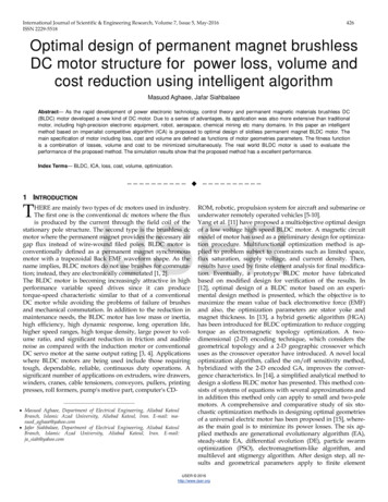
1,6A. Mathematical motor model1,4The machine equations in terms of accordingstator space vector notation is written in a statorfixed reference frame asdψ Sαβ (τ)u Sαβ (τ) rS iSαβ (τ) .(11) dτThe introduced stator flux space vector in (11) isfortunately written in case of weak-saturableisotropic inductances asψ Sαβ (τ) lS iSαβ (τ) ψ Mαβ ,(12) whereby a rotor flux space vector of constantmagnitude is assumed. The governing relation forthe brushless DC feature is derived from (11),(12)asdu Sαβ (τ) rS iSαβ (τ) lSiSαβ (τ) jωψ Mαβ ,(13) dτ whereby any transformation into a rotor fixed(d, q ) reference system is avoided.load torque 0,0760,0790,0810,0830,0850,087time [s]Figure 11. Calculated shaft torque m(t) for a speed range of400 rpm and a constant load of 1.35 Nm.1,61,4load torque [Nm]1,21,00,80,6B. Simplified block diagram of the closed-loopbrushless DC control0,40,2The control is realized with the aid of an outerspeed as well an innermost current 2000frequency [Hz]Figure 12. Fourier coefficients M̂k of the shaft torque for aspeed range of 400 rpm and a constant load of 1.35 Nm.The imported Hall sensor signals, denoted afterthe interface with γmeas, are transformed to a continuous actual speed value with the aid of a Delement. Due to the low number of six Hall sensors, only very rough speed detection is feasible.The smoothed signal by a PT1 is denoted as nact.The actual speed nact is compared with the demanded speed ndem. The difference is in Fig.13applied to the moderate PI speed controller whichdelivers the required motor current magnitude.This value is further limited by the thermal I2Tprotection, which takes implicit use of the actualmeasured motor current iact.V. BRUSHLESS DC CONTROLLED HIGHERHARMONIC AIR-GAP WAVE BASED PERMANENTMAGNET MOTORThe brushless DC magnet motor is operatedwith a space current distribution which does notrotate smoothly but remains fixed in distinct positions within sixty electrical degrees, and thenjumps suddenly to a position sixty electrical degrees ahead [16]. The brushless DC mode is alsoknown as an electronically commutated motoroperation. The current has to be commutatedelectronically between different phases controlledby diverse switching semiconductors [17,18]. Thisis possible due to three Hall sensors whichprovide the necessary six electrical commutationinformation during the rotor shaft movement. Thecurrent magnitude is kept to a required value andthe current flows only through two of the threephases coevally. The generated average mechanical torque remains always constant within thesixty degree electrical periods. The brushless DCcontrol is set up at the hardware in Fig.1.The innermost loop in Fig.13 serves as currentcontrol. The actually measured motor current imeasfirst passes a PT1 smoothing block, before the obtained signal iact is processed with an 8 kHzsampling rate of the current-controller. Depending on the difference between the demanded current magnitudes idem and the smoothed measuredcurrent iact, the necessary motor voltage magnitude udem is calculated with the aid of a PI currentcontroller.5
PT1 smoothingndefPI controllerPI controllerndemudemidemnactI2T monitoringiact PT1 smoothingimeasPT1 smoothingD conversionγmeasnmeasFigure 13. Simplified block diagram of the closed-loop speed and current control.6,0C. Electrical current and harmonic spectrum4,5The influence of the electrical current commutation from one phase to the other can be clearlyseen in the calculated time-dependent course ofFig.14 for rated-load and the speed of 400 rpm.The measured quantity is given in Fig.15. Directcomparison of calculated with measured coursesshows a very good concordance. The implementednumerical analysis is also very suitable to predicteven higher harmonics in the motor current. Thecomplete current spectrum (9) contains the fundamental component Î1 3.84A at 93.3 Hz. More-load current 0650,0670,0700,0720,0740,0760,078time [s]Figure 14. Calculated motor current i(t) for a speed range of400 rpm and a constant load of 1.35 Nm.over, some very distinct peaks within the spectrum could be observed. Several invoked higherharmonic components such as Î5 0.81A at466.6 Hz, Î7 0.62A at 653.3 Hz, Î11 0.31A at1026.3 Hz and Î13 0.21A at 1212.9 Hz are almost causing undesired effects, such as additionalthermal heating.D. Electromagnetic torque and spectrumThe numerical calculated time-dependent mechanical torque m(t) is depicted in Fig.17 for ratedload and a speed value of 400 rpm. It results fromthe series expansion (10) that there exists withinthe harmonic components M̂k , k » 0 almost theFigure 15. Measured motor current i(t) for a speed range of400 rpm and a constant load of 1.35 Nm. One divisioncorresponds to 2 ms in the abscissa and 1.5 A in the ordinate.4,03,5desired constant contribution of M̂0 1.36Nm .3,0load current [A]The known undesired torque fluctuations withinFig.17 can be seen more clearly in the harmonicspectrum depicted in Fig.18. Both distinct highercomponents are found to be M̂6 0.12Nm at2,52,01,51,0559.8 Hz and M̂12 0.09Nm at 1119.6 Hz. Other0,5contributions to the torque ripple are obviouslysuppressed. The occurring undesired load tipeffects are well known to be responsible foreventually undesired noise requency [Hz]Figure 16. Calculated motor current i(t) for a speed range of400 rpm and a constant load of 1.35 Nm.6
1,6sen the quality of the complete drive system. Thevector control method enforces only one distinctfundamental component in the electrical currentconsumption, whereas the brushless DC controlcauses a wide harmonic current spectrum. Undesired load pulsation effects of the unskewed motorcould be slightly reduced by preferring the vectorcontrol method. The applied transient electromagnetic-mechanical finite element calculationmethod with additionally coupled external circuits in the time-domain allows the inclusion ofbasic control features and is therefore very suitable for a straightforward and accurate analysisof the complete converter fed speed-variable drivesystem in advance.1,4load torque 0,0670,0700,0720,0740,0760,078time [s]Figure 17. Calculated shaft torque m(t) for a speed range of400 rpm and a constant load of 1.35 Nm.1,61,4load torque [Nm]1,21,0REFERENCES0,8[1] J.S. Salon, Finite element analysis of electricalmachines, Cambridge University Press: Cambridge,1996.[2] M.J. DeBortoli, Extensions to the finite element methodfor the electromechanical analysis of electricalmachines, PhD Thesis, Rensselaer PolytechnicInstitute, New York, 1992.[3] J.P.A. Bastos and N. Sadowski, Electromagneticmodeling by finite element method, Marcel Dekker:New York/Basel, 2003.[4]P.F. Brosch, Moderne Stromrichterantriebe, Vogel:Würzburg, 1989.[5] W.Leonhard, Control of electrical drives, Springer:Berlin, 2001.[6] G.K. Dubey, Fundamentals of electrical drives, AlphaScience Int.: Pangbourne, 2001.[7] K.B. Bimal, Power electronics and variable frequencydrives: technology and applications, IEEE Press: NewYork, 1996.[8] K. Heumann, Principles of power electronics. Berlin:Springer Verlag, 1986.[9] G. Seguier and G. Labrique, Power electronicconverters: dc to ac conversion. Berlin: Springer Verlag,1989.[10]T. Bödefeld and H. Sequenz, Elektrische Maschinen,Springer: Wien/New York, 1942.[11]P. Vas, Vector control of AC machines, OxfordUniversity Press: Oxford, smethoden, Betriebssicherheit, Instandhaltung,Verlag Pflaum: München, 1998.[13]W. Nowotny and T.A. Lipo, Vector control anddynamics of AC drives, Clarendon Press: Oxford, 2000.[14]P. Vas, Electrical machines and drives: A space-vectortheory approach, Clarendon Press: Oxford, 1996.[15]P. Vas, Parameter estimation, condition monitoring,and diagnosis of electrical machines, Clarendon Press:Oxford, 1993.[16]R. Lehmann, Technik der bürstenlosen Servoantriebe,Elektronik, Vol. 21, 1989.[17]T.J.E. Miller, Brushless permanent magnet andreluctance motor drives, Clarendon Press: Clarendon,1989.[18]J.R. Hendershot and T.J.E. Miller, Design of brushlesspermanent-magnet motors, Oxford university press:Oxford, 2000frequency [Hz]Figure 18. Fourier coefficients M̂k of the shaft torque for aspeed range of 400 rpm and a constant load of 1.35 Nm.VI.APPLICATION AND COMPARISON OF BOTHCONTROL METHODSIn case of the well-balanced motor constructionand a diligent sensor adjustment, the mostly undesired torque fluctuation of the unskewed motordesign still exist within the vector and brushlessDC operational mode. In case of some technicalapplications, this disadvantage could be accepted;otherwise the rotor has to be skewed. However,for many circumstances, the easy unskewedmotor construction and the much cheaper brushless DC control mode in conjunction with thehigher harmonic air-gap wave based motor designis often favorized. Unfortunately, additionalcopper losses and varying iron losses are still reducing the thermal torque speed characteristic. Inorder to overcome those circumstances within certain ranges, the complex vector mode is commonlypreferred.VII. CONCLUSIONThe novel axially unskewed higher harmonicair-gap wave based permanent magnet motortechnology has been analyzed with regard to theclosed-loop vector as well as brushless DC controlmethod. The main focus is thereby given to theverification of previously unknown and almostundesired effects, which could significantly wor-7
the brushless DC mode, within introduced inno-vative permanent magnet motor topologies, as e.g. the higher harmonic air-gap based design, is still a big challenge [4-6]. Several simplifications have to be done in order to treat the analysis in a reasonable way. The implemented main