Transcription
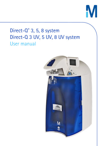
International Journalof Control,Automation,and Systems,2, no.3, pp. 279-288,September Motor2004Developmentof a NovelDirect-DriveTubular vol.LinearBrushlessPermanent-Magnet279Development of a Novel Direct-Drive Tubular LinearBrushless Permanent-Magnet MotorWon-jong Kim and Bryan C. MurphyAbstract: This paper presents a novel design for a tubular linear brushless permanent-magnetmotor. In this design, the magnets in the moving part are oriented in an NS-NS—SN-SN fashionwhich leads to higher magnetic force near the like-pole region. An analytical methodology tocalculate the motor force and to size the actuator was developed. The linear motor is operated inconjunction with a position sensor, three power amplifiers, and a controller to form a completesolution for controlled precision actuation. Real-time digital controllers enhanced the dynamicperformance of the motor, and gain scheduling reduced the effects of a nonlinear dead band. Inits current state, the motor has a rise time of 30 ms, a settling time of 60 ms, and 25% overshootto a 5-mm step command. The motor has a maximum speed of 1.5 m/s and acceleration up to 10g. It has a 10-cm travel range and 26-N maximum pull-out force. The compact size of the motorsuggests it could be used in robotic applications requiring moderate force and precision, such asrobotic-gripper positioning or actuation. The moving part of the motor can extend significantlybeyond its fixed support base. This reaching ability makes it useful in applications requiring asmall, direct-drive actuator, which is required to extend into a spatially constrained environment.Keywords: Direct-drive DC motor, linear actuator, permanent-magnet motor, real-time digitalcontrol, tubular motor.1. INTRODUCTONThe objective of the work described in this paper isto develop a novel linear actuator capable of fast,smooth, precise positioning with a 10-cm actuationrange. The direct-drive tubular linear brushlesspermanent-magnet motor (LBPMM) shown in Fig. 1has a slotless stator to provide smooth translationwithout cogging. This design choice sacrifices thehigher force capabilities that would be possible withiron slots in the stator in favor of smooth actuation.Applications for this type of actuator include precisionpositioning and robotic actuation needs. Linearactuators are used in robot end-effectors such asdexterous hands [1] and as the final link in multi-linkrobotic arms. Budig discusses many types ofapplications for which linear motors are appropriate[2].Some linear actuators are comprised of hydraulic orpneumatic rams, which are good for non-precisionManuscript received April 1, 2004; accepted June 9, 2004.Recommended by Editor Keum-Shik Hong.Won-jong Kim is with the Department of MechanicalEngineering, Texas A&M University, 3123 TAMU, CollegeStation, Texas 77843-3123 USA (e-mail: wjkim@mengr.tamu.edu).Bryan Murphy is with The Boeing Company, InternationalSpace Station, Loads, Dynamics, and Mechanisms division,13100 Space Center Blvd, Houston, TX 77059 USA (e-mail:Bryan.C.Murphy@boeing.com)applications requiring high force. Others use anelectric rotary motor with a lead screw or otherlinkage to convert rotary motion to linear translation,which has serious complications including backlashand increased mass of the moving part due toconnecting linkages or gears. Hence, the LBPMM,which is comprised of permanent magnets andcurrent-carrying coils, is especially suited forprecision positioning applications.There have been many contributions in the field ofLBPMM’s and other direct-drive systems, in whichthe load is propelled directly by the motor. LBPMM’sFig. 1. Assembled tubular linear motor mounted on aprecision optical table shown with brass tubeconnected to the LVDT at right. Thepermanent magnets are within the brass tube.The amplifiers can be seen in the back.
280Won-jong Kim and Bryan C. Murphyare commonly used in single- and multi-degree-offreedom precision positioning applications. Lequesneinvestigated a number of performance criteria forpermanent-magnet linear motor designs withtranslation range from 5 to 20 mm [3]. Kim andTrumper, et. al demonstrated that a six-degree-offreedom planar LBPMM could be used for precisionnanopositioning [4,5]. This setup consists of currentcarrying coils contained within a stationary basebeneath a platen comprised of matrices of permanentmagnets. When energized, the coils levitate the platenand allow significant translation and rotation in theplane of the base plate.Berhan, et al. discussed the use of a Halbachmagnet array [6] in a novel ironless tubular LBPMM[7,8]. The Halbach array is implemented in the formof axisymmetric octagonally-oriented rectangularpermanent magnets, which approximate a cylindricalHalbach array. The primary differences between thecited motor and the proposed design is that theproposed motor has a simpler mover made up ofcylindrical permanent magnets, is more compact insize, and is much easier in construction.Ishiyama, et al. designed a tubular LBPMM thatcan be used to drive a carriage in an image readingdevice and other applications [9]. This design entailsan array of hollow radially-magnetized permanentmagnets, with the poles of each magnet aligned withthe attractive poles of the adjacent magnets. Thisconfiguration is repeated to produce a relatively longtubular array of magnets, which constitutes the fixedpart of the motor. The primary differences betweenthis design and the design proposed herein are themagnetization direction of the magnets and theconfiguration of the motor. The cited design alsoembodies a fixed array of magnets, with the outercoils as the moving part. This is substantially differentfrom the motor discussed in this paper, as in the latterthe tube, which encompasses the permanent magnets,is free to extend out well beyond the support of thebase.Zhu, et al. constructed a tubular LBPMM anddiscussed cogging minimization [10]. In this designmultiple motor topologies are discussed. Radiallymagnetized magnets similar to those in [9] andaxially-magnetized magnets as in the authors’ designwere both proposed as options for the embodiment.This design uses an iron core in the stator, whichinstigates cogging forces into the system. The primaryperformance goal discussed in [10] is to maximize theforce-per-current and force-per-volume ratios. In theproposed design herein, while output force is ofappreciable concern, the primary desire is for precisepositioning.Liaw, et al. developed an LBPMM with robustposition control [11]. Shieh and Tung designed acontroller for an LBPMM used in a manufacturingsystem [12]. Brückl discussed the use of a linearmotor for ultra-precision machine tools [13], which isalso a possible application for our design. Basak andShirkoohi used a software package to compute themagnetic field in DC brushless linear motors withNdFeB magnets [14]. Lee demonstrated a cylindricallinear motor design using toothed sections whichmakes assembly easier and prevents overheating [15].Trumper, et al. discussed electromagnetic arrayscapable of generating field patterns in two and threedimensions by varying current density in the winding[16]. Ishiyama presented a stator design for acylindrical linear motor in which opposing faces ofring shaped permanent magnets are adjacent andpositioned close to each other using a tighteningmechanism [17]. Akmese, et al. described computeraided analysis of machine parameters and themagnetic cogging force using finite elementtechniques [18]. Eastham, et al. discussed theoptimum design of brushless tubular linear machines[19].The concepts given in the aforementioned papers,particularly those discussed in [7-10], incorporatequalities similar to the design proposed here, but withsignificant differences. The proposed design allowsfor compact actuation of a slender cylindrical tube,which is free to extend beyond the support base. Asthe design is ironless and slotless, there is no cogging,which allows smooth translation. The downside of thisironless design is that there is no iron yoke toconcentrate the magnetic field, so the efficiencysuffers. The compact design of the motor makes itapplicable to space-constrained robotics applications.The potential resolution of the system lends itself toapplications in precision positioning.In the following sections, a presentation of theelectromechanical design is given with the governingequations and motor sizing discussed. Next, the designof controllers for particular motion requirements ispresented, as well as the steps taken to optimize thecontrollers for two specific robotic-actuation needs.Several experimental results are given illustrating thesystem response to various inputs, some includingexternally applied loads. The maximum force forwhich the motor is capable is also determined. Thiswork is also discussed in detail in [20].2. ELECTRO-MECHANICAL DESIGN2.1. Design conceptFig. 2 represents the conceptual configuration withoutparticular dimensions assigned to the magnets andcoils. Cylindrical permanent magnets are placed in anNS-NS—SN-SN fashion with spacers between pairs.The magnet pitch is required to match the coil pitch,and arranging magnets (which were convenientlyavailable) together in pairs allowed the magnet
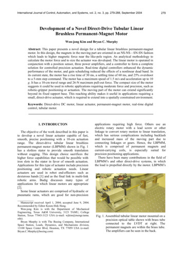
Development of a Novel Direct-Drive Tubular Linear Brushless Permanent-Magnet Motorr'coilθ'CBrC'6BA' 'BC543magnetaluminumspacer21o'MOVERAθz, z'87opolycarbonatespacerSTATORFig. 2. Section view of coils and magnets with brasstube hidden. Coordinates are given for themover frame (primed frame) as well as thestator frame (unprimed frame) that isstationary in space.czhpρZwdyRxFig. 3. Parameters between permanent magnet (left)and current-carrying coil (upper right). Thecoil is represented with a rectangular crosssection.pitch to match the coil pitch. The magnets are fixedwithin a freely sliding brass tube which constitutes themover. Electromagnetic coils are configured in threephases labeled A, B, and C. Each coil has one lead J ( µ0 M ) fz 4π R 2π. 0 0c w Z h2 2π2 c wh2 Z 20from the outermost turn and one from the innermostturn. The coils are arranged in sequence such thatevery third coil is in the same phase. The coilsconstitute the stator, and the mover is placed withinthe stator. As the coils are powered, they exert a forceupon the permanent magnets according to the Lorentzforce equation, which causes translation of the mover.The length (along the z-axis) of the magnets is setto be equal to that of the coils. Therefore the requireddesign parameters are the length of the magnets/coils,the outer radius of the magnet and the inner radius ofthe coil (this pair determines the air gap betweenthem), and the outer radius of the coil. The magnetarray is fixed within a brass tube, space for whichmust be accommodated in the air gap between themagnet and coil arrays.2.2. Motor force calculation and sizingTo determine the particular values for the designparameters, some quantified desired performancecriteria must be established. In this case, theconceptual design guarantees the smooth translationrequirement, as there are no iron slots, which wouldintroduce cogging. The remaining performanceparameter of interest is the maximum output force.The Lorentz force equation, f (J B) dVgoverns the interaction of the coil current andpermanent magnet. The output force is the volumetricintegral of the cross product of the current density inthe coil with the magnetic flux density generated bythe permanent magnet over the whole coil volume.The force of primary interest is the interaction of asingle magnet with a single coil current. Upon furtherexpansion and simplifications due to symmetry, theLorentz force equation becomes (1). Some geometricparameters are given in Fig. 3. A thorough derivationis given in [20], in which material from [21,22] wasquite helpful.The coil inductance and resistance are 0.500 mHand 0.552 Ω, respectively, per coil. A maximumcurrent of 3 A flow through each coil. The magnetschosen for evaluation were cylindrical neodymiumiron boron (NdFeB) magnets. Their maximum energyproduct (BHmax) is 0.4 MJ/m3 (50 MGOe). Themagnets chosen are 10.0-mm (0.395”) in diameter, R 2πd ρdθ d ρdr 0 0 ( z d / 2)2 r 2 ρ 2 2 r ρ cos(θ φ ) dθ d ρ r dφ dz dr ( z d / 2)2 r 2 ρ 2 2 r ρ cos(θ φ ) ρ281(1)
282Won-jong Kim and Bryan C. MurphyRelative Displacement /Current (N/A)-0.20-0.30-0.40Numerically Determined Data PointsLinearly Interpolated Points-0.50-0.60-0.70Fig. 4. Theoretical force per current as a function ofrelative displacement for one magnet with onecoil.9.53-mm (0.375”) long, and have a minimumremanence of 1.20 T. To allow adequate space for the11.1-mm (7/16”) O.D. (outer diameter) brass tube tohouse the magnets and slide freely without contactwithin the coils, the I.D. (inner diameter) of the coilswas chosen to be 12.2 mm, with an O.D. of 33.2 mm.The length (in the z-direction) was selected to be 9.53mm to match that of the magnets. Using AWG #21wire, 179 turns of wire fit within the design envelope.Based on these dimensions, the force per currentbetween a single magnet and single coil as a functionof relative displacement (Z) can be determined using(1). MathCAD was used to solve for this force percurrent for numerous values of Z. These results areillustrated in Fig. 4. The points given in the figure arefrom iterations solved in MathCAD. The linesconnecting the points into a continuous line are fromlinear interpolation between these points.2.3. Mechanical designThe stator consists of nine coils (three per eachphase), corresponding to 1½ pitches. To provide thedesired travel range of 10-cm, several pitches ofmagnets are included, so that there are alwaysmagnets within appreciable force range on both sides(axially) of each coil. Aluminum spacers were usedbetween pairs of magnets so that the magnets could beglued together. The magnets and spacers were glued inplace by coating PC-7 epoxy on the outer surfaces.The magnet pitch consisting of four magnets with twospacers is 63.3 mm. A brass tube was chosen to housethe magnets and spacers. The tube has an 11.1-mm(7/16”) O.D., wall thickness of 0.356 mm (0.014”)and is 305 mm (12.0”) in length. The magnets andspacers are positioned in the brass tube in an NSNS—SN-SN orientation. The magnets within thebrass tube will translate through the nine-coilassembly, as shown in Fig. 2. Nylon bearings whichsupport the brass tube are held in Delrin housingsfixed to both ends of the stator.When gluing the coils together face-to-face, 0.787-mm-thick multi-layer polycarbonate spacers wereused to leave a gap between coils for the lead wirefrom the innermost coil winding to run along the faceof the coil to the outside of the coils. A notch was cutfrom the inner diameter to the outer diameter of eachof the spacers to leave room for the lead wire. Thespacers were trimmed so that the inner diameter of thespacers was larger than that of the coils and so that theouter diameter of the spacers was smaller than that ofthe coils. This allowed the brass tube to slide freelythrough the coils, and also left room for the wire leadson the outside of the coils to be wrapped around to theappropriate location. The effective thickness of theadded polycarbonate spacer (including the glue line onboth faces) was 1.03 mm. Thus, the stator pitchconsisting of six coils with six spacers is 63.3 mm, thesame as the magnet pitch.2.4. CommutationIn order to provide balanced three-phase current tothe motor, a commutation equation relating force andcurrent based on position was required. Forconvenience, the coordinate convention designated inFig. 2 was chosen to correlate with that defined in [8]so that the commutation equation would be applicablewithout significant modification. The commutationequation from said paper is given in (2), where Creplaces a quotient of geometric parameters. 2 iA i C 1 B iC 10 cos γ 1 z0 3 f zd . sin γ 1 z0 3 (2)The variables iA, iB, and iC correspond to the threephase currents applied to the coils. The parameter γ1 isthe magnitude of the spatial wave number of the firstharmonic, γ1 2π/l , where l is the pitch of the motor(63.3 mm). The relative lateral displacement of themover with respect to the stator is denoted z0, and fzd isthe desired axial thrust.Equation (2) provides three equations for only oneunknown, C, as the currents are given, and thedisplacement and force can be readily determined.To find an appropriate value for C, analytical andexperimental procedures were executed. In eachinstance, balanced three-phase currents and adisplacement (z 0 ) were fixed. Upon statisticalinvestigation of the data for C, the median value wasselected. Once C is determined, the controller outputcan be converted to the three desired output currentsas follows. The output from the controller is force,which is multiplied by the geometric quotient C andthe appropriate sinusoidal displacement dependencyas in (2). The maximum swing of the current to thecoils is 3 A, proportional to the output voltage fromthe controller board. Hence the transconductance
Development of a Novel Direct-Drive Tubular Linear Brushless Permanent-Magnet MotorTable 1. Analytical force output.Coil in Phase ACoil in Phase B Coil in Phase CForce/Force/Force/Magnet N/A)(mm)(N/A)(mm)(N/A)1-36.550.00-26.00-0.05-15.45 50.00Force/Current (N/A) -1.16-1.06-1.07Multiplied by 3 Coils -3.47-3.17-3.21Current to Coils (A) -3.00-3.00-3.00Force per Phase (N) 10.409.519.62Total Force (N)29.60amplifier gain is 0.333 A/V.To analytically determine the force capabilities ofthe motor, the individual contributions for eachmagnet-coil interaction must be summed. Since thepitch of the coils matches the pitch of the magnets, theforce contribution from each coil in a single phase isidentical. Thus the force per current for each phase ismultiplied by three, as there are three coils in eachphase. From Fig. 4, it is clear that for magnets beyond30 mm, the force contribution is negligible, so onlythe six closest magnets to each coil are taken intoconsideration.Table 1 enumerates the force contributions betweenthe six nearest magnets and a single coil in each phase.The magnet number corresponds to the magnets aslabeled in Fig. 2. The force per current is summed foreach representative coil, then multiplied by threebecause there are three coils in each phase. This forceper-current value for each phase is multiplied by thecurrent sent through that phase to find the force output.The total force is found by adding the force outputsfrom each phase. Table 1 represents the position andcurrent condition for maximum force output, whichrelaxes the balanced three-phase condition. Themaximum force is determined to be 29.6 N. With thebalanced three-phase condition in place, the maximumforce is 19.4 N.2.5. Experimental setup and instrumentationThe experimental setup is depicted in Fig. 5. Thelinear variable differential transformer (LVDT) isconnected to the mover of the motor through athreaded rod. The LVDT outputs the analog positionsignal to the conditioning circuit, which shifts andfilters it, then sends it to an analog-to-digital (A/D)channel of the DS1104 controller board. Thecontroller board processes the position signal, andoutputs appropriate control signals to the PWMamplifiers. The amplifiers then generate currentsproportional to the voltage, which power the coils andexert force to the permanent magnets fixed in themover, causing translation. The following tioningCircuitPWMAmplifiersLVDTLinear MotorFig. 5. Experimental setup. The position signal readby the LVDT passes through the conditioningcircuit to the controller board, which comparesit with the desired value and ouputs signals tothe amplifiers which power the coils, inducingtranslation.detail the critical instrumentation used in the setup.1) LVDTThe LVDT is comprised of a single primary coil ofwire with secondary coils placed on either side of theprimary coil. The zero position is set by adding aconstant to the input in Simulink. The LVDT isSchaevitz part #02560995-000, model 4000 DC-SE.The analog output swing is 0–5 VDC, with a travelrange of 10 cm. The noise is listed as less than 10mV rms.2) Conditioning CircuitA signal conditioning circuit comprised of twooperational amplifiers, a voltage regulator, and severalresistors was constructed to shift the output voltage ofthe LVDT to match the input swing of the A/Dchannel with which it was interfaced. This circuitwas necessary to maximize the position resolution.An anti-aliasing filter in the form of a first-order RCfilter with a cut-off frequency of 400 Hz was alsoimplemented.3) DS1104 Controller BoardThe DS1104 digital-signal-processing (DSP)controller board from dSPACE provides the interfacebetween the controller and the motor. The DSP boardhas a 250-MHz Power PC 603e with TexasInstruments’ DSP TMS320F240 chip. It contains four16-bit A/D channels, four 12-bit A/D channels, eight16-bit digital-to-analog (D/A) channels, and otherdigital input/output interfaces. We developed a userfriendly interface to provide system control andobservation with the provided Control Desk
Won-jong Kim and Bryan C. MurphyDeveloper along with Matlab/Simulink. One of the16-bit A/D channels was used to transmit data fromthe sensor to the computer, sampling at 5 kHz. ThreeD/A channels were used to output data to the threepulse-width- modulation (PWM) amplifiers.4) PWM AmplifiersThree PWM amplifiers (Model 12A8K fromAdvanced Motion Controls) power the three phasecurrents. Each amplifier is capable of outputting 6 Acontinuously, which is twice as large as the maximumcurrent rating of our tubular motor.181614) 12mm(n 10otisio8P6423. CONTROLLER DESIGN ANDIMPLEMENTATION0In this section, the system modeling and controllerdevelopment is discussed. Various controllers weredeveloped to better achieve the desired performancecharacteristics for robotics applications. In each case,a classical lead-lag controller is the backbone of thesolution. Gain scheduling is implemented to decreasethe effect of the dead-band region of the response.Two primary performance requirement sets areentertained. The first requirement set is for a fast risetime with minimal position noise, which is what isrequired for many precision positioning applications.The second requirement set is for little or noovershoot, as may be required in some roboticsapplications when significant overshoot may implyundesirable impact.3.1. Plant modelThe LVDT allows its iron core to slide withoutcontact, thus contributing no friction forces on thesystem. The nylon bearings located at both ends of thelinear motor contribute very little friction to thesystem, and friction is therefore neglected initiallyfrom the system model. Thus the system can bemodeled as a pure mass. The mass of the movermeasured 175 g on a precision scale. Thecorresponding plant transfer function isY (s)1 .f ( s ) 0.175s 220Position (mm)284(3)3.2. Controller designSince the system is modeled as a pure mass, themodel is marginally stable. To decrease the rise timeand add damping, a lead compensator was added. Toimprove the steady-state performance of the system, alag compensator was included as well. To haveacceptable damping, the system should have a phasemargin greater than 60 . For zero steady-state error, apole is placed at the origin of the s-plane. The requiredminimum rise time limits the lower bound of the012345t (s)6789Fig. 6. System response to 20-mm step before gainscheduling (dashed line) and after gainscheduling (solid line).system gain, however in practice the actual gain wasmuch higher than this bound. Thus, the system gain,remaining pole and zeros were determined throughmany trial-and-error iterations. The Matlab function‘rltool’ was used to finalize the controller parametersto achieve appropriate dynamic performances.Equation (4) gives the discrete-time version of acontroller with a 5-kHz sampling frequency.1.7 105( z 0.996 )( z 0.9608).( z 1)( z 0.67032 )(4)This controller yields a phase margin of 73.6 at thecrossover frequency of 40 Hz, which is applicable forapplications requiring a fast step response with 20–30% overshoot acceptable. Many other controllerswere also developed and their performance wasinspected to determine their applicability to particularrobotics applications, such as no-overshootapplications or high-speed point-to-point positioning.3.3. Gain schedulingIn experimental step responses, to be discussed inSection 4, the two most significant problems werehigh amplitude noise in the system, and a significantdead-band region present. The noise was significantlyreduced with software filtering, component redesign,and fixing the motor on a vibration isolation table.The dead-band region present in system responses isdue to nonlinear friction present in the system.When the motor moves to a point near the desiredposition, it takes substantial time for it to makeanother move towards the final position. A pole in thecontroller placed at the origin of the s-plane sums theerror. Because the motor is near the final position, theerror is small, however, it takes time for the controller
Development of a Novel Direct-Drive Tubular Linear Brushless Permanent-Magnet MotorIn order to determine the widest scope ofapplications for which the motor is appropriate,numerous experiments were performed to test itscapabilities. Several controller modifications wereintroduced to optimize control for the differentapplications. These modifications include filtering,gain scheduling, and path planning. Note that all datafor the position reading is taken after filtering of thesignal from the LVDT.4.1. Experimentally determined actuation forceTo experimentally find the maximum pull-out forceof the motor, fixed currents were applied to the threephases of the coils and an external force was appliedto the mover via a hanging load and pulley, as shownin Fig. 7. The load was increased incrementally byadding small weights to the hanging mass until theforce reached the motor’s pull-out force, and themotor released the load to fall. The last added weightwas removed, and the remaining mass was resolvedon a scale. This mass was multiplied by thegravitational constant to determine the force. Whenthe maximum current (3 A) was applied to each phaseof coils, the pullout force was found to be 26.3 N.This value correlates with the theoretically-predictedvalue of 29.6 N, found using (1).4.2. Step responsesThe step response of a linear actuator is a usefultool to gauge its performance in point-to-pointmaneuverability. Many applications require anactuator to move from one position to another, in asfast a time as possible. Other important characteristicsare the percent overshoot, settling time, and steadystate error.pulleyprecision vibrationisolation tabledeadweightFig. 7. Experimental setup to determine maximumpullout force. The load hangs from a stringthat is held by the motor via a pulley. Load isincrementally increased to the hanging massby adding small weights.0.06)mm(noitsioPPosition (mm)4. EXPERMENTAL RESULTSSTATORMOVER0.040.020-0.02-0.2Position (mm)to accumulate commanding currents large enough forthe motor to overcome the friction, resulting in asignificant time delay.In order to eliminate this dead-band region, gainscheduling was implemented. A lookup table wasincluded in the Simulink controller that effectivelyincreased the gain by a factor when the position waswithin a small threshold on either side of the desiredposition. A ‘dead’ area within 50 µm was allowed toremain in order to prevent exacerbation of the noisewhen near the desired final value. Fig. 6 gives thesystem response to a 20-mm input command, with andwithout gain scheduling implemented. The controllerused here is specifically designed to reach the desiredposition without overshoot, however this caused it tobe slow, especially for large steps. Through thismethod of gain scheduling, the effect of the dead-bandregion was significantly diminished, with the rise timereduced from over 7 s to less than 0.8 s.285)mm(notisioP6543210-1-2000.20.02t (s)0.04t (s)0.40.060.60.80.080.1Fig. 8. System response to 40-µm step (top) and to a 5mm step (bottom).The first plot in Fig. 8 shows the system stepresponse to a 40-µm step command. The rise time isless than 0.3 s, and the settling time is about 0.4 s.These transient responses are rather slow consideringthe 40-Hz crossover frequency of the control system.It is believed to be that the friction in the nylonbearings and the dead-band slowed this microscalemotion. The second plot in Fig. 8 shows a 5-mm stepresponse. The rise time is about 20 ms and the settlingtime is about 60 ms without significant nonlineareffects.It is clear that the positioning resolution of thesystem is better than 20 µm. The limitation on theposition resolution arises from the noise prevalent inthe LVDT sensor and its electronics. Incorporation ofa sensor capable of finer precision would yieldsignificantly better position resolution from the motor.Fig. 9 illustrates the system response to much largersteps, ranging from 2 to 5 cm with 1-cm increment.
Won-jong Kim and Bryan C. Murphy8080707060605050)mm(notsoP40Position (mm)Position (mm)2863020403020101000-10-0.200.20.4t (s)0.60.8-1014.3. Velocity profile trackingAnother common tool used to gauge theperformance of a motor is its ability to track a certainvelocity profile, e.g. a trapezoidal velocity profile.This profile consists of linearly accelerating to adesired velocity, holding that velocity for some time,then decelerating back down. The position readingfrom the sensor is differentiated with respect to timeto determine
Brushless Permanent-Magnet Motor Won-jong Kim and Bryan C. Murphy Abstract: This paper presents a novel design for a tubular linear brushless permanent-magnet motor. In this design, the magnets in the moving part are oriented in an NS-NS—SN-SN fashion which leads to higher magnetic forc