Transcription
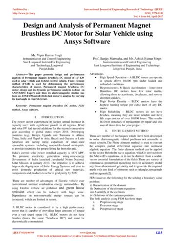
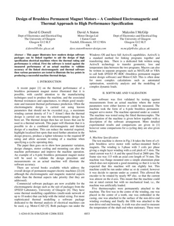
Design of Brushless Permanent Magnet Motors – A Combined Electromagnetic andThermal Approach to High Performance SpecificationDavid G DorrellDavid A StatonMalcolm I McGilpDept of Electronics and Electrical EngThe University of GlasgowGlasgow G12 8LTUKd.dorrell@elec.gla.ac.ukMotor Design Ltd1 Eaton CourtTetchill, Ellesmere, SY12 9DAUKdave.staton@motor-design.comDept of Electronics and Electrical EngThe University of GlasgowGlasgow G12 8LTUKm.mcgilp@elec.gla.ac.ukAbstract – This paper illustrates how modern design softwarepackages can be linked together to aid the design of highspecification electrical machines where the thermal rating andperformance is critical. First the software is tested against themeasured performance of an actual machine to validateaccuracy of the linked electromagnetic and thermal softwarethen various parameters are tested to illustrate the key points inproducing a successful machine thermal design.I. INTRODUCTIONA recent paper [1] on the thermal performance of abrushless permanent magnet motor illustrated that it ispossible, with careful attention to the manufacturingtechniques used to produce the machine, and the associatedthermal resistances and capacitances, to obtain good steadystate and transient thermal performance prediction. Often theelectromagnetic design is carried out using knownparameters that should not be exceeded (e.g., a maximumwinding current density of 5 to 7 A/mm2) then the thermaldesign is carried out once the electromagnetic design hasbeen set. The thermal design then has set losses that can beused in a thermal network. This paper will illustrate that it ispossible to do a combined electromagnetic and thermaldesign of a machine. This can reduce the material required,highlight localized hot-spots that need further attention in thedesign process, produce a tighter tolerance to the required IPrating and allow accurate re-rating of a machine whenspecifying a cyclic operating duty.The paper then goes on to show how parameter variation,design changes, motor cooling and mounting can alter themachine performance and improve the machine operation.An example of a 6-pole brushless permanent magnet motorwill be used to validate the design procedure andmeasurements on an actual machine will illustrate thesoftware accuracy.There are several books available which address theoverall design of permanent-magnet electric machines [2]-[4]although the electromagnetic and magnetic material aspectsrather than the thermal aspects take priority (but they areaddressed).Commercial software packages are now available for theelectromagnetic design such as the suit of packages from theSPEED Laboratory, University of Glasgow [4]. They havesome thermal modelling capabilities (multi-node network ofup to 10 nodes) that can help with the initial sizing. For moresophisticated thermal modelling a software packagededicated to the thermal analysis of electrical machines canbe used, e.g. Motor-CAD [5]. Both packages run under the1-4244-0136-4/06/ 20.00 '2006 IEEEWindows OS and have full ActiveX capabilities. ActiveX isa standard method for linking programs together andtransferring data. There is a dedicated link written usingActiveX technology to transfer geometric, loss andtemperature data between the two programs. Macros can alsobe written in separate programs such as MATLAB or VBAto call both SPEED PC-BDC (brushless permanent magnetmotor design software) and Motor-CAD. This is often donefor more complex calculations such as automatedoptimisation, sensitivity analysis and the modelling ofcomplex dynamic loads.II. SOFTWARE AND VALIDATIONThe software was first validated by testing againstmeasurements from an actual machine where the motorparameters were either known or could be measured. Themachine took the form of a 6-pole brushless permanentmagnet servo motor. The machine operated under ac control.The machine was tested using the fitted thermocouples. Thespecification of the machine is given below together with adescription of the software arrangement. More detailedexperimental results and comparisons are given in [1]however some comparisons for a cycling duty are also givenbelow.A. Machine SpecificationThe test machine is shown in Fig.1 It takes the form of a 6pole brushless servo motor with surface-mounted SmComagnets. The winding is 3-phase with 3 coils per phasegiving a single layer winding with a coil pitch of 3 slots. Therated current was 6.1 A and the speed fixed at 2600 rpm. Theframe size was 115 with an axial core length of 74 mm. Themachine was flange mounted onto a simple aluminium platewhich does not represent a good mounting so that it is too beexpected that this machine will run slightly hot. Thismachine could be run under either ac or dc control, howeverit was decide to operate under ac control. This allowed theencoder to be rotated by nearly 90º elec. so that the currentwas almost on the d-axis. This meant that the machine couldrun at rated current but with no mechanical load, i.e., themachine was artificially loaded.Five thermocouples were permanently attached to themachine. The first was in the centre of the winding, one wasplaced in the centre of a tooth, one was embedded in thecasing, one was attached to the surface of the non-drive-endwinding overhang and finally the fifth was attached to thenon-drive-end end housing. A sixth was also used to measurethe temperature of the shaft end when stationary. These were4853
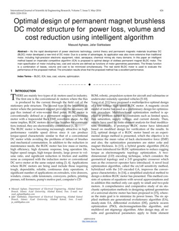
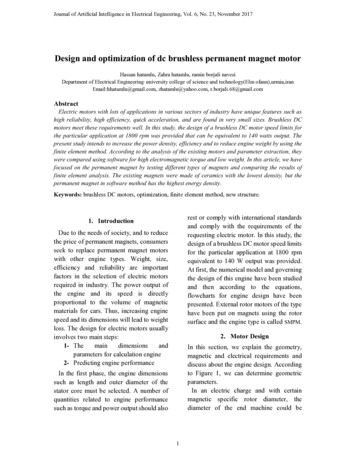
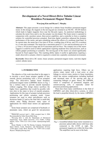
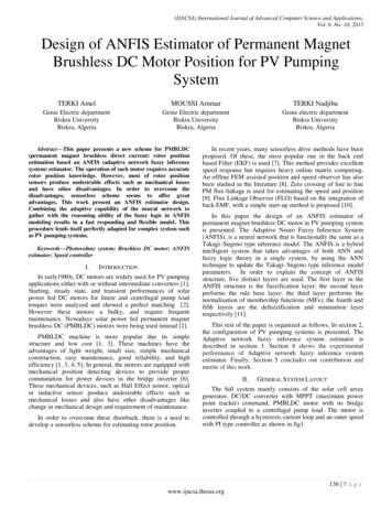
logged using a data logger so that the temperatures could becontinuously monitored during operation.also offering specific calculation facilities such as inductionmotor leakage calculation in PC-IMD through direct linkage.Fig. 3. Cross-section showing fining from Motor-CADFig. 1. Test MachineB. Machine Models in PC-BDC and Motor CadThe machine parameters were first put into the PC-BDC(in fact the manufacturer uses SPEED as their motor designdatabase format so they were able to furnish a PC-BDCdesign file for this machine. Fig. 2 shows the cross section ofthe machine in PC-BDC. This geometry could be importedinto Motor Cad and additional parameters, concerning thingssuch as axial and radial casing and ducting, different types ofcooling, gaskets between components and insulation andwinding impregnation could be set. The cross-section andaxial views in Motor Cad are shown in Figs. 3 and 4. Furtherdetails of the mechanical detailing and parameter adjustmentare given in [1].Fig. 4. Axial sectionFig. 2. Machine cross section from PC-BDCC. Design Software FormatWhile [1] details the linking of the software it is worthnoting some points here. PC-BDC is called from the MotorCAD environment. The dialog that controls the data to betransferred is shown in Fig. 5. This link was developed byjoint co-operation using Windows ActiveX (COM) softwaretechnology. Many CAD packages are exploring the use ofsoftware linkage; indeed SPEED software now links intoseveral finite element packages and can act as the front-endgeometrical input with the possibilities of developing furthercontrols for the FEA from SPEED. Some FEA packages areFig. 5. SPEED link in Motor-CADD. Experimental ValidationFig. 6 shows the comparison of simulated machinetemperatures against for measured for a duty cycle where themachine runs at rated current at 2600 rpm for the twentyminutes then it is switched on and off over successive tenminute intervals. This is shown for three locations – thewinding, the stator tooth and the shaft. While the shaft seemsto be incorrect this is because the temperature was measuredusing an uncalibrated hand-help thermometer and it isassumed that this was measuring about five degrees out in4854
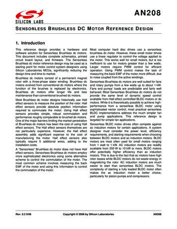
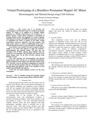
absolute terms. Excellent correlation is found with the othertemperature points. Only these three points are illustrated forclarity however the other points that were measured alsoshowed good correlation similar to the winding and toothtemperature variation. These were given in [1].9080magnets are running quite cool and the magnetization is verystable. The remanence at 20 ºC is 0.885 with a temperaturecoefficient of -0.045 %/ºC.The steady-state magnettemperature at rated Iph is 128 ºC giving a Br of 0.84. Thetemperature of the magnets are calculated using Motor-CADwhile an iterative procedure is used to obtain the machineoperating point where the magnetization and copperresistance and losses are varying with time.170Magnet Temp [deg C]6050400.8500.7400.60.5300.420Magnet Temperature10Magnet Remanence0.30.20.1030Shaft (front) (sim)Stator Tooth (sim)Winding Layer [4] (sim)20020Shaft (mes)Tooth (mes)Winding Slot (mes)4060Core Section Copper LossTotal Copper Loss4060Time [mins]80Fig. 8. Variation of magnet remanence with temperatureE. Thermal Network and Steady State SolutionThe thermal network is shown in Fig. 9. This consists ofmany network components with a full set of thermalresistances for steady-state solution and thermal capacitancesfor transient solution. A full steady-state temperature solutionis given in Table I.In Table I it can be seen that the winding is the criticaltemperature component in a brushless PM machine. Thelosses are dominated by the copper loss and the active slotconductors are is divided into several shells; also the frontand rear end-winding sections are additional separate losscomponents. In Fig. 9 it can be seen that the verticalresistances tend to represent heat moving in in the radialdirection while horizontal resistances tend to represent heatmoving in the axial direction.Total End Winding LossStator Back IronStator Teeth1202080Time [mins]14000Fig. 6. Comparison between measured and simulated duty cycling100Loss [W]0.960Remanent Magnetism [T]Temp [deg C]7080604020III. PARAMETER VARIATION002040Time [mins]6080Fig. 7. Variation of machine loss with timeWhile [1] concentrated on the temperature variation is italso possible to obtain a breakdown of the losses within themachine and these are shown in Fig. 7. These are importantto highlight the possible areas of design improvement. It canbe seen that the losses are dominated by the copper loss. Thisis split into two – the losses in the slots and the end windinglosses. The core loss is restricted to the stator and dividedinto tooth and yoke losses. The idea behind this is that it isnow possible to identify where deign improvements can bemade; e.g., does the yoke or tooth width need to be increasedor decreased or does the slot impregnation need to beimproved or extra cooling put into the end winding regions.Also included is Fig. 8 which shows the variation of themagnet remanence Br since this is an important issue formotor flux and torque production. In this case the machineWe will first look at some simple parameter variations andhow the motor temperature varies. We will focus on thetemperature of the windings since this is the key point thatcan lead to thermal runaway. The machine itself was ratedwith Class F insulation. Therefore the machine has a thermalrating which specifies a maximum temperature of 155 ºC andan ambient temperature up to 40 ºC.In this motor is it found that thermal runaway occurs in thestator windings. However this is not always the case andindeed thermal runaway can occur in the magnets; as thetemperature increases, a reduction in magnetization occurs. Ifthe machine is torque controlled then the controller will keepincreasing the current, so that the motor temperature willkeep increasing and a stable point is never obtained. Thermalrunaway in the magnets can cause permanentdemagnetization in the motor.4855
Fig. 9. Schematic of Thermal NetworkTABLE ISTEADY STATE THERMAL SOLUTIONThermal NodeT [Ambient]T [Housing - Active]T [Housing-Overhang (F)]T [Housing - Front]T [Endcap - Front]T [Bearing - Front]T [Flange Mounted Plate]T [Housing - Overhang (R)]T [Housing - Rear]T [Endcap - Rear]T [Bearing - Rear]T [Stator Lam (tooth)]T [Stator Lam (back iron)]T [Stator Surface]T [Rotor Surface]T [Magnet]T [Rotor Lamination]T [Shaft - Center]Temp[dec 6108.7130.3124.2130.2128128127.9127.8Thermal NodeT [Shaft Ohang - Front]T [Shaft - Front]T [Shaft Ohang - Rear]T [Shaft - Rear]T[End Space - F]T[End Space - R]T [Encoder]T [Encoder Case]T [Winding Average]T [Active Winding Ave.]T [End Winding Average]T [Winding Layer 1]T [Winding Layer 2]T [Winding Layer 3]T [Winding Layer 4]T [Winding Layer 5]T [EWdg (F)]T [EWdg (R)]square, this is slowly increased in the simulation to 3000 mmsquare and the variation of the steady-state temperaturesassessed. This illustrates that, for flange mounted machines,there is considerable cooling through the front mounting.It is also possible to dissipate heat through the shaft.Therefore the front of the shaft can be locked down to acertain temperature. In this instance the shaft has a 30 mmextension. In Fig. 11 the front of the shaft extension is lockedto 25 ºC with a mounting plate of 140 mm square and 3000mm square and compared to the temperatures when it is notattached to as load sink. It can be seen that while the windingtemperature is pulled down slightly, it really only affects thelocal area around the front end shaft and bearing.Temp[deg 146.6144.3146.8148.5149.3149.4146.3146.4B. Overheating Via Excessive AmbientThe machine can overheat if the ambient becomes toohigh. This is illustrated in Fig. 12 where the ambient isincreased and the steady-state temperatures are shown. Thetemperature ramps up at a constant rate.A. Temperature Variation with Mounting Plate and LoadAttachmentThe measurements were conducted with a small mountingplate. Many manufacturers assume that the mounting is aheat sink and we will illustrate this here. In Fig. 10 themounting plate is changed. The actual plate is 140 mm4856
these extremes convergence temperatures will varydepending on the starting temperatures. Fig. 13 shows thetransient over the first 10 minutes, at 4 minutes the machinehas already reached the thermal ratings and it is still steeplyramping up.16012010030080Housing [Active]604020T [Housing - Active]T [Stator Lam (tooth)]T [Endcap - Rear]T [Shaft - Front]T[End Space - R]T [Winding Layer 4]005001000150020002500Square Mounting Plate Side Length [mm]3000Fig. 10. Variation of temperature with mounting plate size160Stator ToothShaft [Front]200Shaft [Rear]Winding Layer415010050140Temperature [deg C]Endcap [Rear]250Temperature [deg C]Temperature [deg C]14001200100246Simulation time [mins]810Fig. 13. Transient simulation with three times rated current80IV. DESIGN IMPROVEMENTS6040A. Temperature Variation with Winding ImpregnationThe winding impregnation can greatly affect thetemperature distribution. There are several parameters thatcan be changed; here, however, we will concentrate on twoparameters – the thermal conductivity of the impregnationresin (which is usually about 0.2 for standard resin but highperformance ones are available which can be up to 1) and theimpregnation goodness factor (which is an indication to thelevel of impregnation – in this machine is was found to belimited so that the goodness factor was set to 0.7). Table IIshows the variation of the machine temperatures when thegoodness is improved to 0.95 and then the impregnationconductivity is changes to 1 for both the resin and the wireinsulation. If can be seen that there is a 9 ºC reduction inwinding temperature which can be important in a machinethat is temperature critical.Plate 140 mm 2140 mm 2 (Front shaft 25 deg C)Plate 3000 mm 23000 mm 2 (Front shaft 25 deg C)200T [Housing T [Endcap T [Stator- Active]- Rear](tooth)]T [Shaft T[End T [WindingFront] Space - R] Layer 4]Fig. 11. Variation of temperature with mounting plate size and loadattachment of front shaft200Machine Temp [deg C]18016014012010080T [Housing - Active]T [Endcap - Rear]T [Stator Lam (tooth)]T [Shaft - Front]T[End Space - R]T [Winding Layer 4]6020304050Ambient Temperature [dec C]6070Fig. 12. Variation of machine temperatures with ambientC. Overheating via OverloadThe machine with the small plate mounting is marginal interms of its thermal performance and rated current. We willnow investigate its overload properties. At three timesoverload current (18.3 Arms) thermal runaway occurs so thatthe iterative procedure breaks down. In fact at 10 % error inconvergence requires 28 iterations (the other simulations inthis paper use 1 % error and converge in 2 to 5 iterations).This gives a winding temperature of 1890 ºC which is clearlyunreasonable, subsequent simulations do converge fasterbecause the winding and magnet temperatures are set to theprevious solution temperatures. With a further single shotsolution this reduces to 1699 ºC which is still quite close. AtTABLE IIVARIATION OF WINDING LAYER 4 TEMP WITH IMPREGNATIONImpregnation level and conductivityWinding Temp [ºC]Goodness 0.7, conductivity 0.2, wire insulation conductivity 0.2 149.3Goodness 0.95, conductivity 0.2, wire insulation conductivity 0.2 141.8Goodness 0.7, conductivity 1, wire insulation conductivity 0.2 141.9Goodness 0.95, conductivity 1, wire insulation conductivity 0.2 141.1Goodness 0.7, conductivity 1, wire insulation conductivity 1140.4Goodness 0.95, conductivity 1, wire insulation conductivity 1140.0B. Temperature Variation with Gasket Thickness of FrontHousingIt was found on dismantling the machine that a gasketwas inserted between the front housing and the main casingwhich was about 0.25 mm thick. As a rule of thumb this sortof gasket has a thermal conductivity which is about ten timesthat of air so that it was represented as an air-gap of 0.025mm. If this was removed and replaced by an air-gap of 0.05mm (typical for a metal-metal joint without a conductivesealant) then the steady-state temperature of the winding4857
dropped from 149.7 ºC to 147 ºC while the front end-captemperature increases from 90.7 ºC to 97.9 ºC.300300Temperature [deg C]250200150100Test MachineImproved Impregnation and No Gasket50Temperature [deg C]250C. Combined Improved Impregnation, Gasket Removal andIncreased Mount Plate SizeIf we use all the improved impregnation techniques inSection IV.A and remove the gasket discussed in SectionIV.B then we can reduce the steady-state windingtemperature to 136.3 ºC in the slot which is now lower thanthe end windings temperature, which is 137.7 ºC. We canalso use a larger mounting plate (3m square) and this reducesthe winding temperature to 96.4 ºC. This illustrates that the agood reduction in steady-state temperature can be obtainedby reducing series-connected thermal resistances together.Further to this we can also look at the transientperformance during overload as described in Section III.Cwhere the there is three times over-current. This is shown inFig. 14. The small iterative improvements in manufacturinglead to an improvement in the region of one minute until thethermal limit of the machine is reached when starting fromcold. However, using the larger mounting plate seems tomake little difference, it should be remembered that theconvergence error is quite large with these simulations soaccuracy will not be as good as at rated current.46Simulation time [mins]8100Natural CoolingForced Cooling00246Simulation time [mins]810Fig. 15. Transient overload characteristics – comparison betweennatural and forced air coolingV. CONCLUSIONSThis paper illustrates that it is possible to accurately modelthe thermal performance of an electrical machine usinglinked electromagnetic and thermal simulation software. Thiswas verified experimentally and the machine was found to bemarginal in terms of its thermal rating when mounted on alight mounting plate. It was then demonstrated that themachine would run cooler if mounted on a larger plate andthen various small design changes illustrated several methodsthan can be used to improve the thermal performance if it ismarginal.The transient overload performance was also addressed,which is important when considering the machine toleranceto overloading. It was also illustrated that force air cooling isa very effective way to improve the machine steady-statethermal performance, even without changing the machinedesign but it is less effective on a transient overload.VI. REFERENCES0215050Improved Impregnation, No Gasket, 3 m 2 Mounting Plate3 m 2 Mounting Plate Only020010Fig. 14. Transient overload characteristicsD. Forced CoolingThe most common way to reduce the motor temperaturesis to introduce forced air cooling. However space constraintsprevents detailed discussion of this here however, simply byintroducing a forced air-flow over the machine casing of 5m/s then the winding temperature can be reduced from 149.7ºC to 108.1 ºC which clearly shows that this is the mosteffective way to reduce the motor temperature. If forced-aircooling is used in conjunction with the impregnationimprovement and large 3000 mm square mounting plate thenthe steady-state winding temperature is now even lower at79.7 ºC.In terms of the transient performance, Fig. 15 shows thewinding temperature over the first ten minutes with naturalcooling and forces air cooling without any change in machinegeometry. It appears that the forced-air cooling actually haslittle effect on the initial transient performance.[1] D. G. Dorrell, D. A. Staton, J. Kahout, D. Hawkins andM. I. McGilp, ”Linked Electromagnetic and ThermalModelling of a Permanent Magnet Motor”, IEE PowerElectronics, Machines and Drives Conference, Dublin,April 2006.[1] J. R. Ireland, Ceramic Permanent-Magnet Motors, NewYork, McGraw-Hill Book Company, 1968.[2] J. R. Hendershot, T. J. E. Miller, Design of BrushlessPermanent-Magnet Motors, Oxford, Clarendon Press,1994.[3] L. R. Moskowitz, Permanent magnet Design andApplication Handbook, Florida, Krieger PublishingCompany, 1995.[4] TJE Miller, SPEED’s Electrical Motors, SPEEDLaboratory, University of Glasgow 2004.[5] D. A. Staton, Motor-CAD V2, Motor Design Ltd,October 2005.4858
design changes, motor cooling and mounting can alter the machine performance and improve the machine operation. An example of a 6-pole brushless permanent magnet motor will be used to validate the design procedure and measurements on an actual machine will illustrate the software accu