Transcription
(IJACSA) International Journal of Advanced Computer Science and Applications,Vol. 6, No. 10, 2015Design of ANFIS Estimator of Permanent MagnetBrushless DC Motor Position for PV PumpingSystemTERKI AmelMOUSSI AmmarTERKI NadjibaGenie Electric departmentBiskra UniversityBiskra, AlgeriaGenie Electric departmentBiskra UniversityBiskra, AlgeriaGenie electric departmentBiskra UniversityBiskra, AlgeriaAbstract—This paper presents a new scheme for PMBLDC(permanent magnet brushless direct current) rotor positionestimation based an ANFIS (adaptive network fuzzy inferencesystem) estimator. The operation of such motor requires accuraterotor position knowledge. However, most of rotor positionsensors produce undesirable effects such as mechanical lossesand have other disadvantages. In order to overcome thedisadvantages, sensorless scheme seems to offer greatadvantages. This work present an ANFIS estimator design.Combining the adaptive capability of the neural network togather with the reasoning ability of the fuzzy logic in ANFISmodeling results in a fast responding and flexible model. Thisprocedure lends itself perfectly adapted for complex system suchas PV pumping systems.Keywords—Photovoltaic system; Brushless DC motor; ANFISestimator; Speed controllerI.INTRODUCTIONIn early1980s, DC motors are widely used for PV pumpingapplications either with or without intermediate converters [1].Starting, steady state, and transient performances of solarpower fed DC motors for linear and centrifugal pump loadtorques were analyzed and showed a perfect matching [2].However these motors a bulky, and require frequentmaintenance. Nowadays solar power fed permanent magnetbrushless DC (PMBLDC) motors were being used instead [2].PMBLDC machine is more popular due its simplestructure and low cost [1, 3]. These machines have theadvantages of light weight, small size, simple mechanicalconstruction, easy maintenance, good reliability, and highefficiency [1, 3, 4, 5]. In general, the motors are equipped withmechanical position detecting devices to provide propercommutation for power devices in the bridge inverter [6].These mechanical devices, such as Hall Effect sensor, opticalor inductive sensor produce undesirable effects such asmechanical losses and also have other disadvantages likechange in mechanical design and requirement of maintenance.In order to overcome these drawback, there is a need todevelop a sensorless scheme for estimating rotor position.In recent years, many sensorless drive methods have beenproposed. Of these, the most popular one in the back emfbased Filter (EKF) is used [7]. This method provides excellentspeed response but requires heavy online matrix computing.An offline FEM assisted position and speed observer has alsobeen studied in the literature [8]. Zero crossing of line to linePM flux linkage is used for estimating the speed and position[9]. Flux Linkage Observer (FLO) based on the integration ofback EMF, with a simple start-up method is proposed [10].In this paper the design of an ANFIS estimator ofpermanent magnet brushless DC motor in PV pumping systemis presented. The Adaptive Neuro Fuzzy Inference System(ANFIS), is a neural network that is functionally the same as aTakagi–Sugeno type inference model. The ANFIS is a hybridintelligent system that takes advantages of both ANN andfuzzy logic theory in a single system, by using the ANNtechnique to update the Takagi–Sugeno type inference modelparameters. In order to explain the concept of ANFISstructure, five distinct layers are used. The first layer in theANFIS structure is the fuzzification layer; the second layerperforms the rule base layer; the third layer performs thenormalisation of membership functions (MFs); the fourth andfifth layers are the defuzzification and summation layerrespectively [11].This rest of the paper is organized as follows. In section 2,the configuration of PV pumping systems is presented, TheAdaptive network fuzzy inference system estimator isdescribed in section 3. Section 4 shows the experimentalperformance of Adaptive network fuzzy inference systemestimator. Finally, Section 5 concludes our contribution andmerits of this work.II.GENERAL SYSTEM LAYOUTThe full system mainly consists of the solar cell arraygenerator, DC/DC converter with MPPT (maximum powerpoint tracker) command, PMBLDC motor with its bridgeinverter coupled to a centrifugal pump load. The motor iscontrolled through a hysteresis current loop and an outer speedwith PI type controller as shown in fig1.136 P a g ewww.ijacsa.thesai.org
(IJACSA) International Journal of Advanced Computer Science and Applications,Vol. 6, No. 10, 2015PhotovoltaicGeneratorDC/DCPMBLDCInverterPumpia -(ib ic)MPPTi a* ref emhysteresisCurrentcontroller3iaibicic * ᶱd/dtANFISEstimatorFig. 1. Overall system configurationVbn Rib p b ebA. PV generator modelThe characteristic of the Photovoltaic generator can bepresented by the following nonlinear equation [4]:I I sc I o [exp((V Rs I )(V Rs I )) 1] VthRsh(1)Isc PV array short circuit current,PV array reverse saturation current,The flux expressions are given by the followingexpressions:Rs PV array series resistance,Vth PV array thermal voltage.The thermal voltage Vth and t reverse saturation current Ioare successively identified by [4]:I o I sc (Vop Rs I op ) I oP exp Vrh (2)()(10)()(11)()(12)Where Ls: the self-inductance and M: the mutualinductance.And(13)(3)B. Permanent magnet Brush-Less DC motor modelThe simplified schematic of PMBLDC motor who has atrapezoidal electromotive force, the use of Park transform isnot the best approach in modelling the machine. Instead thenatural approach in used where the emf is generated withrespect to rotor position [4]. The operating sequences of themachine can be subdivided into six cycles with respect to rotorposition as shown in table II.Therefore by substituting Eq.13 in Eqs 10, 11 and 12:()(14)()(15)()(16)From the electrical equations 4, 5 and 6, the followingsystem is obtained[][][ ][][ ][ ] (17)With Leq LS –MFrom this system, the decoupled phase equations areobtained and the explicit current equations are given by:The electric of the motor can be described by [4]Van Ri a p a ea(7)(8)Vcn Vc0 Vn0(9)Where R: per phase stator resistance. ia,b,c and a,b,c arerespectively phase currents of phases a, b and c and total fluxlinkage of a,b and c. p: Laplace operator.Rsh PV array equivalent shunt resistance,(Vop R s I op Voc )I oplog(1 )I scVan Va0 Vn0Vbn Vb0 Vn0IPV Array output current,Vth (6)WithWhere:Io(5)Vcn Ric p c ec(4)137 P a g ewww.ijacsa.thesai.org
(IJACSA) International Journal of Advanced Computer Science and Applications,Vol. 6, No. 10, 2015 [ ][[[ ][][ ][ ]](18)]The mechanical part is expressed by the followingequation:(19)With:Te: electromagnetic torque.Tr: Load torque: speedJ : moment of inertiaB : viscose friction coefficientNeglecting the frictional coefficient and takingwhere P is the pole pairs number, (19) can written as: () ( ) ( ) ( )( )( )()The value of the torque reference is given by [4]:( )()( )( )(25)) the speed error of previous interval is,Where (( ) is the speed error of working interval.andarespeed controller gains.D. Current controlSeveral techniques can be used to control the phase currentof the PMBLDC motor. In this paper a hysteresis currentcontroller is used. It has the major advantage of not requiringmachine parameters to be known. However the commutationfrequency is not constant [4]. It depends on many factors suchas the applied voltage, the back emf, hysteresis band .etc.(20)) (21)And the angular position is expressed by (23)(24)Maximum value of commutation frequency is obtained atstarting and is given by [4]:The developed torque can be expressed by(compared with the reference speed ( ) and the resultingerror is estimated at the nth sampling instant as:(22)(26)The commutations are obtained by comparing actualcurrents ia.b.c to a rectangular reference i*a.b.c and by keepingthem in hysteresis band . The commutation sequences ofswitches are summarised in the table I. [5].TABLE I.THE CMMUTATION SEQUENCES OF SWITCHES*Si ia (ia I )T1 onT4 offVa U/2* I )Si ia (iaSi i (i* I )bbSi i (i* I )bb*Si ic (ic I )Si ic (ic* I )T1 offT4 onVa -U/2T2 onT5 offVb U/2T2 offT5 onVb -U/2T3 onT6 offVc U/2T3 offT6 onVc -U/2E. Pump modelA centrifugal type is used. It can be described as anaerodynamic load which is characterised by the following loadequation [4]:Fig. 2. Back e.m.f and current waves forms for phase a, b and cC. Speed controlPI speed controller is widely used in industry due to itsease in design and simple structure. The rotor speed ( ) is(27)Where A is the pump constant138 P a g ewww.ijacsa.thesai.org
(IJACSA) International Journal of Advanced Computer Science and Applications,Vol. 6, No. 10, 2015TABLE II.III.OPERATING SEQUENCES WITH RESPECT TO ROTOR POSITIONANFIS ESTIMATORThe adaptive network fuzzy inference system play asignificant role in the field of artificial intelligence. Itcombines the advantages of a fuzzy controller as well as quickresponse and adaptability nature of artificial neural network[11]. Hence using this scheme one can avoid the use of aposition sensor which produces mechanical losses in themotor. Different configurations of adaptive network fuzzyinference system have been tested and the best one that givesthe minimum error value is presented in fig6.The Algorithm of the model structure was constructed asshown in Fig.3. The membership functions were obtainedfrom the data set of the back emfs which were first normalizedfor loading Data. Then generate Fis, built on sugeno structure,which is obtained by creating of input membership function:number (tree inputs) & type (triangular) and outputtype(linear). The choice of optimization method (hybrid) isobtained by Train Fis. If the results are satisfactory (error isminimum) after test Fis, denormalized procedure is done andgo to application thereafter. The ANFIS structure consists of 5layers of neurons, each of which having a very specificbehavior.Original DataNormalizationLoad Data(testing, training, checking)Generate FisInput: 1. Number of Mfs2. type of MfOutput: Mf typeTrain FisOptimization MethodeEpoch number: errorTest fisFrom these, second, third and fifth layer have constantbehavior, while layers 1 and 4 have varying parameters.Layer 1: consists of five adaptive neurons in which thefuzzification is performed, that is: the grade of membership tothe defined membership functions of the input is evaluated.f i1 µ Ai (x)NoyesDenormalization(28)Where x is the input to ith neurons and Ai is membershipfunction correspond to variable x.ApplicationFig. 3. Algorithm of the ANFIS modelThe membership function µAi (x) is triangular.Layer2: consists of 125neurons, each node outputrepresents the firing weight of a rule gives than:Wk µ Ai (x) µ Bj (y)MinimumError(29)Layer3: consists of 125 neurons, every node calculates theratio of every rule firing weight to the sum of all rule firingweights.k : represent the number of rule, i : represent the number ofx partition and j : number of y partition.Wk Wk Wi(30)139 P a g ewww.ijacsa.thesai.org
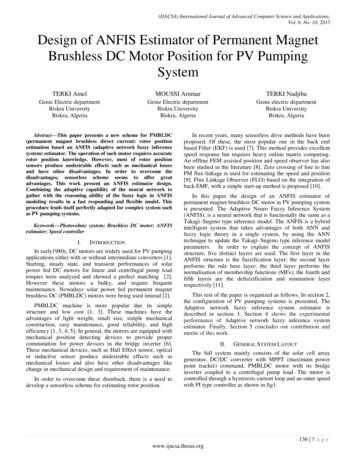
(IJACSA) International Journal of Advanced Computer Science and Applications,Vol. 6, No. 10, 2015Layer 4: consists of 125 neurons. Nodes in layer 4 areadaptive nodes in which the consequent evaluation inference iscalculated, its output is defined as:f k4 Wk f k Wk pk x qk y rk (31)Wk is the output of layer3 and pi , qi , ri is calledconsequent parameters.5 Wk f k4(32)kIV.150100Eab(v)500-50-100Layer5: Finally, is single node in layer 5, where sums allthe outputs from 4th layer to compute the overall output of thenetwork:f200SIMULATION RESULTSThe entire ANFIS network architecture is represented inthe Fig.6. The inputs are the three line to line back emfs of themotor namely Eab, Ebc and Eca Fig4. And the desired outputis the estimated rotor position angle. For producing the aboverelationship with least possible error, a five layer feed forwardadaptive network fuzzy inference system is used. The inputlayer consists of five neurons that have their inputs as the threeline to line back emfs, the three hidden layers consists of 125each and the output layer consists of a single neuron whoseoutput is the estimated position of the rotor. The relationshipbetween the back emf and the position of the rotor is shown inthe Fig.5.Fig.7 shows estimated rotor position by adaptative networkfuzzy inference system and the error, along with real rotorposition it’s a case without regulation. Fig.8 shows theestimated rotor position by adaptive network fuzzy inferencesystem and the error, along with real rotor position the case iswith PI speed control. In the comparison of the cases withcontrol (PI regulator) and at without control, The controlledsystem attains the steady state in (0.04s) greater than the casewithout regulation the system attains the steady statein(0.023s), so the PI regulator slows the dynamic responses.The performance of thThe performance of the trainedadaptive network fuzzy inference system is found to have veryminimal errors witch is about 1.303e-7 as seen in the Fig.7(without control).-150-20001234Angle teta (rd)567Fig. 5. The back emf EabFor Fig.8 (with PI controller), the error is 7.8386e -9. Theerror of output of ANFIS and real rotor position sensor arecompared through Fig.7 and Fig.8 respectively. It is clear thatthe error in Fig.8 is too small (7.8386e -9) than these in Fig.7(1.303e-7). The proposed scheme works efficiently where theusage of neural network topology together with fuzzy logic inThe adaptive network, ANFIS, not only includes thecharacteristics of both methods, but also eliminates somedisadvantages of their lonely-used case.Input1, MFInt1 mf1EabInt2 mf2AggregatedOutput1EbctetaThe back fems (V)15010050Eac0-50Int3 mf5-100Rule 125-15000.020.040.060.08Time (sec)0.10.120.14Output MF 125Fig. 6. Structure of ANFIS model proposedFig. 4. The inputs curves140 P a g ewww.ijacsa.thesai.org
(IJACSA) International Journal of Advanced Computer Science and Applications,Vol. 6, No. 10, 2015la position 0.08-0.0600.020.040.06la position estimée70.080.10.12temp(sec)0.140.160.18Fig. 8. Simulation Results with PI rd)0.01CONCLUSIONThe developed ANFIS models were successful inestimating rotor position of PMBLDC motor used in PVpumping system. In this paper the design of adaptive networkfuzzy inference system based sensorless scheme wasdeveloped for permanent magnet brushless DC motor. Theproposed scheme works efficiently for both with control (PIregulator) and at without control. It was found that the error isvery minimal and this is smaller in system with regulation,than these without regulation. Also adaptive network fuzzyinference system based estimator is very 04temp(sec)0.050.060.070.08Fig. 7. Simulation Results without controlla position réelleThis scheme not only eliminates the position sensor,thereby cutting the cost but also transforms the drive into ahighly efficient drive by eliminating losses caused by positionsensors. The estimation error is found to be very minimalproving that the developed system is a very efficient and areliable .10.12temp(sec)0.140.160.180.2la position 0.10.12temp(sec)0.140.160.180.2REFERENCESA.Moussi, A. Saadi, A. achour, Greg Asher, Photovoltaic pumpingsystems technologies trends, Larhyss journal ,2003,pp.127-150.PackiamPeriasamy, N.K.Jain,I.P.Singh, A review on development ofphotovoltaic water pumping system, Renew.and Sustainable.Energ.Reviews, Vol. 43 ,2015, pp. 918–925.MetinDemirtas,AslanDenizKaraoglan, Optimization of PI parametersfor DSP-based permanent magnet brushless motor drive using responsesurface methodology, Energy Conversion and Management, Vol. 56,2012, pp. 104–111.A. Terki, A. Moussi, A. Betka, N. Terki, An improved efficiency offuzzy logic control of PMBLDCfor PV pumping system,Appl.Math.Model , Vol. 2, 2012, pp. 934-944.A.Moussi, A.Terki, Greg Asher, Hysteresis current controller ofpermanent Magnet Brushless DC motor PV pumping system, ASME,2005, pp. 523-528 [International Solar Energy conference].T. Hiyama, Neural network based estimation of maximum powergeneration from PV modules using environmental information, IEEETrans. EC, Vol.12, 199, pp. 241–247.A. Ungurean, V. Coroban-Schramel and I. Boldea, Sensorless controlof a BLDC PM motor based on I-f starting and Back-EMF zero-crossingdetection, OPTIM ’10, 2012, pp. 377-382 [Optimization of Electricaland Electronic Equipment Conference,OPTIM ’10.IEEE 12thInternational].141 P a g ewww.ijacsa.thesai.org0.2
(IJACSA) International Journal of Advanced Computer Science and Applications,Vol. 6, No. 10, 2015[8][9]AlinStirban, Ion Boldea, and Gheorghe-DanielAndreescu, MotionSensorless Control of BLDC-PM Motor With Offline FEM-InformationAssisted Position and Speed Observer, IEEE Trans. Ind. Appl, Vol. 48,2012, pp. 1950-1958.LiviuIoanIepure, Ion Boldea and FredeBlaabjerg, Hybrid I-f starting andobserver-based sensorless control of single phase BLDC-PM Motordrives, IEEE Trans. Ind. Electron, Vol.59, 2012,pp. 3436 – 3444.[10] SreepriyaR&RagamRajagopal, Sensorless Control of Three PhaseBLDC Motor Drive with Improved Flux observer, ICCC, 2013, pp.292297 [IEEE International Conference on Control Communication andComputing].[11] Ali M. Abdulshahed, AndrewP. Longstaff, Simon Fletcher, Alan Myers,Thermal error modelling of machine tools based on ANFIS withfuzzy cmeans clustering using a thermal imaging camera, Appl. Math. Model,Vol. 39, 2015, pp. 1837–1852.APPENDIXThe PV generator, motor and pump used in this study have the followingparameters: PV generator Modules AEG-40.(Temperature T 25 Cand solar insolation E 1000W/m².)Open circuit voltage22.40 VShort circuit current2.410 ASeries resistance0.450Current temperature coefficient0.06%/ CVoltage temperature coefficient0.40%/ CCentrifugal pumpRated speed3000 rev/minRated power521 WFlowrate2.597 l/sHead14.11 mEfficiency69%Brushless DC motorRated power690 WRated speed3000 rev/minRated voltage200-220VRated current4.8 APer phase resistance1Per phase inductance5 mHPoles number6E.m.f constant0.47142 P a g ewww.ijacsa.thesai.org
In this paper the design of an ANFIS estimator of permanent magnet brushless DC motor in PV pumping system is presented. The Adaptive Neuro Fuzzy Inference System (ANFIS), is a neural network that is functionally the same as a