Transcription
Section VIIPhotogrammetric SurveysTable of ContentsVII. Photogrammetric Surveys .VII-3A. General .VII-31. Photogrammetric Advantages .VII-32. Photogrammetric Disadvantages .VII-4B. Photography.VII-41. General .VII-42. Photograph Collection .VII-4a. Aircraft .VII-4b. Camera .VII-5c. Mission Planning.VII-7d. Flight Conditions .VII-8e. Scale Calculation .VII-10f. Scale Variation .VII-12g. True Scale .VII-13h. Uniform Scale .VII-13i. Vertical Digital Photography.VII-13j. Overlapping Imagery .VII-14k. Acceptable Tolerances .VII-14l. Image Post-Processing .VII-15m. Image Storage .VII-16C. Photographic Ground Control .VII-161. General .VII-162. Photo Control Points .VII-18a. 2-legged “photo control” Targets .VII-18b. 3-legged “wye/project control” Targets .VII-19c. Obstructions.VII-20D. Photograph Annotation .VII-20
Photogrammetric Surveys1. Annotated Photo Enlargements .VII-20E. Terrain, Planimetric, and Digital Image Collection.VII-231. General .VII-232. Collection Format .VII-233. Planimetric Mapping .VII-234. Digital Terrain Model (DTM) .VII-245. Accuracy Standards .VII-256. Accuracy Testing .VII-277. Digital Imagery .VII-27VII-2Revised November, 2018
Section VIIVII. Photogrammetric SurveysA. GeneralPhotogrammetry can be defined as the science of making reliable measurements usingphotographs or digital photo imagery to locate features on or above the surface of the earth. Theend result produces the coordinate (X, Y, and Z) position of a particular point, planimetricfeature, or 3-D graphic representation of the terrain.Photogrammetry has evolved into a reliable substitution of ground surveying activities whenlarge area mapping is necessary. It can relieve survey crews of the most tedious, time consumingtasks required to produce topographic maps and Digital Terrain Models (DTMs). Ground surveymethods will always remain an indispensable part of Photogrammetry and are not replaceable bythe photogrammetric process.WYDOT’s Photogrammetry Unit compiles or obtains terrain and planimetric data, then convertsit into useful information for various WYDOT programs. That information includes but is notlimited to ortho rectified imagery, topographic mapping, digital terrain models, 3-D point clouds,and various other mapping related tasks used for engineering and design purposes. The data maybe obtained through ground survey methods, lidar terrestrial scanning methods, photogrammetricmethods, or a combination of the three to produce a complete and accurate representation of thetopography as it exists.Increased information of existing terrain conditions allows designers the ability to explorealternative alignments without the need to collect additional field information. Surveys collectedphotogrammetrically, have both advantages and disadvantages when compared with groundsurveys.1. Photogrammetric Advantages Aerial imagery provides a permanent record of the conditions as they existed at the timethe photograph was taken. The imagery can be used to convey information to the general public, local, state orfederal agencies, and other WYDOT programs. Terrain data and mapping features can be extracted from stereo image models with littleeffort and at a low cost. Large area mapping and digital terrain models can be accomplished quicker and at alower cost when compared to ground survey methods. Photogrammetry can be used in locations that are difficult or impossible to access fromthe ground. If information must be re-surveyed or re-evaluated, it is not necessary to performexpensive field work. The image stereo model can be re-loaded and measurementsverified and/or additional information compiled in a timely manner.Revised November, 2018VII-3
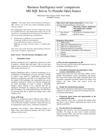
Photogrammetric Surveys2. Photogrammetric Disadvantages Seasonal weather patterns that produce increased wind and cloud cover may hamper theability to perform the mission. Solar conditions such as sun angles less than 30 above the horizon will cast longshadows. Sun angles greater than 45 will produce sun spots on the image. It may be difficult or impossible to collect measurements in areas with dark shadows,dense vegetation, snow, water, or overhanging features.B. Photography1. GeneralThis section discusses the equipment, materials, and methods used to obtain the imagerytaken from WYDOT’s Photogrammetry aircraft. It will also provide a summary review ofthe software used in mission planning, flight management, and image post processing toproduce high resolution panchromatic, color, and color near infrared 12 bit imagery. Theimagery is used to create engineering grade mapping and terrain files for planning and designactivities.2. Photograph Collectiona. AircraftThe Department’s aircraft used to flying aerial photo missions is a Cessna Caravan 208.It has an approximate maximum flying altitude of 25,000 ft. and a maximum air speed of175 knots (200 mph). The aircraft is based out of Cheyenne and is maintained byWYDOT’s Aeronautics Division. Due to the weather and ground conditions required toproduce quality images, WYDOT has a pilot and digital mapping camera operator onstaff to allow for the flexibility necessary in scheduling photo missions.Image VII-1. WYDOT photography plane (208 Cessna Caravan)VII-4Revised November, 2018
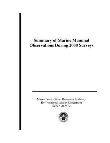
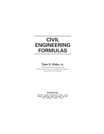
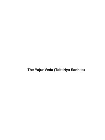
Section VIIThe aircraft has been structurally and electrically modified to host our DMC, digitalmapping camera, which is mounted on and through the belly of the aircraft. Anelectrically operated sliding door has been added to the exterior belly of the aircraft overthe camera hole. This door was added to protect the lens from fly rock during takeoff andlandings.A heads-up display mounted to the instrument panel allows the pilot to navigate over theplanned mission and communicate with the camera operator as the mission is beingcollected.Image VII-2. Sliding door for lens protectionImage VII-3. Heads-up pilot displayb. CameraIn 2007, WYDOT purchased a Zeiss Digital Mapping Camera system to replace ourexisting film based system. The camera system is comprised of a DMC main cameraassembly, gyro stabilization mount, integrated computer system, and solid state disk(SSD) for on-board data storage of images.Image VII-4. WYDOT DMC (Digital Mapping Camera System)Revised November, 2018VII-5
Photogrammetric SurveysThe DMC also has an inertial measurement unit (IMU) to improve the onboard GPSsolution and strengthen the aerial triangulation results during the bridging process. TheGyro stabilized mount removes the effects of vibration in the imagery during collection.The gyro mount also compensates for roll, pitch, and yaw of the aircraft so the principleand nadir points are relatively equal. An electronic forward motion compensator (FMC)removes blurriness resulting from the forward motion of the aircraft at the time of theexposure.The DMC main camera has 8 individual cameras that are autonomous, 4 panchromatic,and 4 multispectral (red, green, blue, and near infrared). These cameras are able toproduce images in black and white, colored, or colored near infrared with a 12 bitresolution. Each image is approximately 272 megabits and the SSD can store roughly1000 images.The camera focal length is 4.72” (120 mm), with a sensor dimension (also known as thenegative in film cameras) of 3.63” x 6.53” (92.16 mm x 165.89 mm). A basic principleof the optics is that all light rays pass through the nodal point (center of the lens).Therefore, the center of the lens is the reference point for measuring the distance aboveground. The basic geometric relationship shown in Figure VII-1 is that of similartriangles.Figure VII-1. Theoretical camera exposure diagram.VII-6Revised November, 2018
Section VIITable VII-1 shows the relationship between flying heights, ground coverage, andresolution quality.Ground CoverageAlong Flight tion(in/pixel)Urban Projects (plains)12501.509601728Urban Projects (mountainous terrain)15001.8011522074Suburban Projects18002.1613822488Rural Projects (plains)20002.4015362765Rural Projects (mountainous h altitude city planning imagery950011.40729513131Project TypeTable VII-1. Image coverage.c. Mission PlanningOnce the project limits and the type of project, rural or urban, have been identified, theappropriate flying height is determined to provide adequate photo coverage for mapping.The flying height determines the flight line target spacing to be physically laid out by thesurvey crew. Table VII-2 shows flying height, flight line and wing point target spacingand ft)Urban Projects (plains)1250Urban Projects (mountainous terrain)Project TypeApproximate WingPoint TargetDistance frommission flight line770Min.(ft)575Max.(ft)6501500920690780Suburban Projects18001100825935Rural Projects (plains)200012309201045Rural Projects (mountainous terrain)2400147411051250Table VII-2. Targeting spacing.Revised November, 2018VII-7
Photogrammetric SurveysAs the target locations are identified, geographic coordinates for each location arerecorded for use in the mission planning software. Mission planning is conducted usingZ/I Mission planning software. The mission example below shows some of the featuresof the planning software.Figure VII-2. Z/I Mission planning software.The software offers the ability to import photo control onto a digital quad map of theproject location. Flight run parameters such as terrain elevation, AG (above groundflying height), exposure overlap, and flight line trigger limit are then entered. Theproposed beginning and end of each flight line are identified and accepted. The missionflight line exposures and exposure foot prints now appear to show coverage. At this pointthe flight lines and exposures can be edited if necessary.When complete, the mission is exported to a Google Earth file for review to ensure theproject limits are covered. Mission .apf or .afl output files are generated and then downloaded onto the camera flight navigation System, Z\I Inflight.d. Flight ConditionsObtaining imagery for mapping purposes depends on a multiple of factors that impact thequality of the image and thus the mapping compiled from it. Those factors includeweather, ground, sun angle, and equipment. Fortunately, Wyoming has a longphotographic season or “window of opportunity” to complete photo missions in asuccessful and timely manner.VII-8Revised November, 2018
Section VII(1) Weather & GroundWeather and ground conditions in Wyoming are at times difficult to predict whencoordinating targeting and photo mission activities. Prolonged mission delays requiresurvey crews to revisit and refresh photo control targets until the mission can becompleted. Ideal conditions include clear skies, no winds aloft, and dry ground.Wind Conditions: Strong winds cause upper air turbulence that makes it difficult tomaintain good direction and a stable platform for photography.Cloud, smoke or hazy conditions: Heavy scattered cloud cover casts dark shadowswhile grey overcast skies create poor lighting. Both conditions degrade the imageryand the ability to collect engineering quality terrain data. Low level clouds, smoke,or haze occurring below the planned mission obstruct a clear view of the ground andprevent or severely degrade collection of data.Ground conditions: Vegetation growth is a concern late spring through early fall.The presence of snow, ice, or flooding due to spring runoff or excessive soil moisturewill obstruct collect and may produce sun hot spots from reflection.(2) SeasonsFor optimum sunlight conditions for engineering quality photography, the sun’sdirection and angle above the horizon are critical. The optimum sun angle formapping imagery is between 30 and 45 above the horizon. Angles above 30 provide enough reflective light and minimize the effects of long shadows. Sun anglesbelow 45 eliminate shadows and hot spots created by the aircraft. During the wintermonths, the sun is lower, so the acceptable light angle is available only for a fewhours around midday. During the summer months, there are a couple of hours in themorning and afternoon when “windows of opportunity” occur. The midday sun isunacceptable due to the presence of sun spots and aircraft shadows. These optimalphotography times vary throughout the year and can be found in Table VII-3. Nonengineering quality images such as systems, reconnaissance, and snow studies can betaken with a sun angle greater than 45 . Early spring is the best time to take mapping images. By then, winter snows havehopefully melted and left matted down vegetation. Crops and vegetation have notbegun to grow or are in the early stages of growth. This minimizes theinterference in obtaining reliable vertical measurements caused by standing weedsor grasses. In areas of deciduous trees, early spring is best before leaves have budded out.Late autumn can be ideal as well after the leaves have fallen from the trees. In areas of conifer (evergreen) forests and open prairie, images can be takenalmost any time between spring snow melt and autumn snowfall. As the name implies, snow study images have to be taken while there aresufficient accumulations of snowfall.Revised November, 2018VII-9
Photogrammetric SurveysTable VII-3. Aerial photography windows of opportunity.Time determinations obtained from www.susdesign.com/sunangle. These times are valid at latitude43 N latitude and 108 W longitude, and elevation 6000’. For each longitudinal degree east, subtract4 minutes from each end of the time interval. For each longitudinal degree west, add 4 minutes fromeach end of the time interval.e. Scale CalculationThe similar triangle relationship, as shown in Figure VII-1, is the basis for calculationsinvolving scale, ground coverage, and flying height. The relative scale of the image canbe calculated in different manners depending upon the requirements. The followingequations can be used for scale calculation:VII-10Revised November, 2018
Section VIIScale D/d H/f (H’ - h)/fd distance on photograph (a-b)D distance on ground (A-B)H flying height above average groundf focal length of camera lensH’ flying height above mean sea levelh average ground elevationScale Calculation Example:H 1800 ft. and f 4.72 in.1:1 Image Scale H/f 1800 ft./4.72 in. 380 ft./in.If the flight height is not known, look for objects that are identifiable on the ground andon the photo. Take a measurement between the objects on both and divide thephotograph measurement into the ground measurement to get the photo scale.Photo scale can also be expressed as a representative fraction or ratio. A ratio is withoutunits but can be expressed in any unit of measurement. The units are the same (i.e., aratio of 1:24000 or 1/24000 means 1 unit is the same as 24000 units). Applying this to anaerial image, 1 inch on the photo equals 24000” (or 2000’) on the ground. Flying heightrequirements for the desired mapping scales are located in Table VII-4.FlightHeight(ft)(1” ’)RatioUrban Projects (plains)12502651:3180Urban Projects (mountainous terrain)15003201:3840Suburban Projects18003801:4560Rural Projects (plains)20004251:5100Rural Projects (mountainous terrain)24005101:6120Systems707515001:18000High altitude city planning imagery950020001:24000Project TypePhoto ScaleTable VII-4. Aerial photography chart.Revised November, 2018VII-11
Photogrammetric Surveysf. Scale VariationThe hypothetical situation in Figure VII-1 will result in an image that has a uniform scale.However, there are four reasons why this situation, for practical purposes, will not occurin the real world. Those situations affecting the scale of the image are shown in FigureVII-3. Due to changes in ground elevation, tilted optical axis, flying altitude, and earth’scurvature the stated scale of a given image is an approximate, non-uniform scale.Figure VII-3. Scale variations.VII-12Revised November, 2018
Section VIIg. True ScaleSince WYDOT’s Photogrammetry & Surveys Section (P&S) uses an average groundelevation in the calculations for flying height, the true scale of a photo print cannot bedetermined without making ground measurements between objects that are identifiableon the image. The ground distance and the distance on the image can be used in theformula given on page VII-12 to calculate the true scale. This true scale calculation issemi-accurate only between the two points used. The image will not have a uniformscale until all the variations have been removed.h. Uniform ScaleOrthographic projection is the only process that will create a truly uniformly scaleddigital image. These projections are commonly called ortho-photos and are the onlyproducts that can be classified (by definition) as a map. They are created by matchingeach individual DTM ground shot with the image location the shot was collected from.The final ortho-image has been rectified using thousands of ground shots per imagemodel. If a DTM does not exist, image rectification can be performed at a lesser qualityusing photo control points or a USGS Digital Elevation Model (DEM). This type ofrectification process can remove the major effects of scale variations but cannot removeall the effects.i. Vertical Digital PhotographyVertical digital photography refers to the direction of the camera’s optical axis, which isin the direction of gravity. This is the position of the camera in which the image’sPrinciple point and Nadir point are the same during the exposure process. The Principlepoint is the point where the perpendicular projection through the center of thelens intersects the photo image center. The Nadir point is the vertical projection fromthe camera center through a point on the photo image as shown in Figure VII-4.Figure VII-4. Image orientationRevised November, 2018VII-13
Photogrammetric SurveysThe truly vertical situation occurs rarely in the real world, as diagramed in Figure VII-4a,but it better reflects the situation identified in Figure VII-4b. This is why a point calledthe Isocenter and Nadir point play an important role in Photogrammetry. The Isocenterfalls halfway between the Nadir and Principle point and is the location where all tiltdisplacement on the image radiates from. The Nadir point is the location where allelevation displacement radiates from.j. Overlapping ImageryAerial photography taken from above is rarely a single shot event. Multiple photographstaken along a flight path are generally taken to ensure complete photo coverage of anarea. To achieve this we must have overlap between photo images. The overlapping ofphotos end to end is termed end lap. An end lap of 30% will avoid potential missingareas of coverage due to the effects of turbulence. Imagery collected for use in stereoviewing, an end lap of 60% is considered ideal.For block coverage of an area at a specific photo scale, it is often necessary to fly parallelstrips of aerial photography. The adjacent strips also overlap each other. Thisoverlapping area is termed side lap and is generally specified at 30% to ensure goodcoverage.k. Acceptable TolerancesThe acceptable tolerance for altitude variation during image collection is plus 5% orminus 2% of the predetermined altitude. Thus, if the desired altitude is 2000’ aboveground (AG), the acceptable range for altitude is between 2100’ AG and 1960’ AG. Forboth urban and rural projects, the trigger limit is set to 200’ either side of the flight linewhile the systems imagery is set to 300’. The trigger limit is the planned flight pathcorridor the aircraft must maintain during image collection process. If the aircraft straysbeyond that corridor, the camera will disengage from image collection. The incompleteflight strip will need to be redone.Image end lap tolerances throughout a flight strip shall average not less than 57% or morethan 62%. No individual end lap within a strip shall be less than 55% or greater than68%. Side lap may vary from 20% to 40% unless otherwise specified.In addition to satisfying altitude, end lap, and side lap requirements, other factorscontributing to the acceptance or rejection of photography are course correction, crab, tilt,and image quality. The crab and tilt can be somewhat compensated by the gyro stabilizedcamera mount. For crab and changes in course correction, the resultant error betweenimages cannot exceed 3 . The tilt within a single frame may not exceed 4 , nor shall thedifference in tilt between two consecutive frames exceed 4 . See Figure VII-5. Theaverage tilt for all images of the same scale cannot exceed 1 . The combined effects ofaircraft course correction, crab, and tilt must not result in an apparent crab greater than 5 on successive images. Apparent crab is defined as the angle between the intended flightpath and the line between adjacent image principal points within the same flight line.VII-14Revised November, 2018
Section VIIFigure VII-5. Effects of wind and turbulence on aircraft during photo collection.l. Image Post-ProcessingThe task of processing the 4 panchromatic and 4 multispectral raw images captured bythe DMC’s 8 individual cameras is performed by Z/I’s Post Processing software (PPS).The process converts the 8 individual images into a standard central-perspective image.These images have to be processed to compensate for numerous radiometric factors.Radiometric correction is a process of assigning pixels a value from 0 to 256 on themonochromatic scale and up to 16,384 shades of color. The pixel resolution can either be8 or 12-bit, with 12-bit being the highest quality image. This will produce an image thatis distinguishable from different light intensities and allows the photogrammetrist toadjust the image contrast to improve data collection. Generally, hundreds of images arecollected during each photo mission. To increase our image processing capability, Z/I’sdistributive software allows PPS the ability to function on multiple computers.Scale distortion is another issue to address with aerial imagery as it increases the fartherwe move away from the image principle point. To resolve this problem, Z/I’sImageStation Aerial Triangulation (ISAT) software matches multi-ray tie points betweenadjacent images using a robust built-in bundle adjustment that removes distortions toproduce an image with spatial intelligence.Revised November, 2018VII-15
Photogrammetric SurveysAfter all these steps, the end result is a geo-referenced colored panchromatic sharpenedimage with a size of 13,824 x 7,680 pixels, or a 106 mega-pixel image.m. Image StorageIn the past P&S was required to store all aerial film photography in a physical locationfor future retrieval by the Department or other outside entities. Even though we are nowa fully digital shop, we still must store those images as a record of historical value andfuture retrieval. However, they are not kept in a physical location, rather than are storedon a dedicated server. All newly acquired DMC processed imagery and scannedhistorical aerial film photography, are placed on that server. To manage this enormousamount of data, WYDOT has purchased a 36 TB (terra byte) Dell Power Vault Server forstorage of all imagery.C. Photographic Ground Control1. GeneralTo make precise and meaningful measurements from aerial photographs, it is essential torelate the photo images to the actual ground surface. This is achieved by physically tyinghorizontal and vertical positions of various photo identifiable points or pre-flight targetingplaced within the project photo limits.Figure VII-6. Two photo stereo model.Three photo control points are required at the beginning and end of each planned flight strip.The flight line target spacing is a factor of the flight altitude to insure at least one photocontrol target falls within each digital image. Wing points are typically placed on either sideof the flight path, every other flight interval space, at a preferred distance of 75% - 85% ofthe target interval spacing. Figure VII-7 is an example of the targeting layout for a typicalWYDOT project.VII-16Revised November, 2018
Section VIIFigure VII-7. Photo targeting and flight line diagram example.With the advancements in GPS and digital camera technology mission planning and in-flightguidance software have greatly reduced flight time, collection problems, and errors due tomisplaced targeting. It has allowed the pilot the ability to concentrate on flying the aircraftrather than searching for and staying on the correct flight path. Flight line and altitude,image overlap, and collection locations are all predetermined in the office using Z/I Missionor Lieca MissionPro planning software. Z/I in-flight reads the mission files to guide the pilotover the project flight line. The camera will automatically cycle over each preset exposurelocation along the flight path. Because of the onboard GPS and internal camera IMU, eachimage has spatial intelligence at the time of collection. When combined with the groundcontrol, a stronger bridging solution is achieved during the auto triangulation process.Images with spatial intelligence reduce the amount of targets required for aerial triangulationby tying each image together. Aerial triangulation (sometimes referred to as bridging) issimilar in theory to the field survey process of triangulation. It establishes a coordinaterelationship between the project control points and the supplemental bridging points.Revised November, 2018VII-17
Photogrammetric SurveysBecause of the time and labor savings, all photogrammetrically collected projects arebridged. Bridging also allows for a check of the field measurements and the elimination ofsome field work in inhospitable areas (e.g. adverse terrain and areas without permission tosurvey).For some projects only requiring imagery for GIS purposes, it is possible to not have anyestablished photo control to create this product. A set of GPS base stations, collecting at halfsecond intervals, positioned over known monuments within in the area are more thanadequate. The rectification process is then accomplished using USGS DEM’s, and the GPSsolution created from the on board GPS/IMU and ground base stations. With the limitationsof signal strength and terrain conditions, this process works best on projects located in areaswith open terrain. The advantage of this procedure is to eliminate the man-hours required fortargeting activities.2. Photo Control PointsPhoto pick points can be used, but the potential for error increases. Confusion may occur onwhich point for the field to tie or which point P&S should use. It is generally preferred to setphoto control targets for mapping projects prior to image collection. Photo pick points aresometimes used if a target has been lost.Photo mission targets are placed with an 8” plastic or painted disk centered over a controlpoint (1” hub or PK nail). Plastic or painted
produce images in black and white, colored, or colored near infrared with a 12 bit resolution. Each image is approximately 272 megabits and the SSD can store roughly 1000 images. The camera focal length is 4.72” (120 mm), with a sensor dimension (also known as the negative