Transcription
Autodesk Civil 3D 2022Fundamentals SDCP U B L I C AT I O N SBetter Textbooks. Lower Prices.www.SDCpublications.com
Visit the following websites to learn more about this book:Powered by TCPDF (www.tcpdf.org)
ChapterSurvey, Points, and LineworkThis chapter focuses on automated Field to Finish tools that aid in drafting anaccurate and efficient Existing Conditions Plan. These tools create a correctexisting topography, property lines, right-of-ways, and center line locations basedon survey data collected in the field. You will learn how to create parcels from alegal description using the Autodesk Civil 3D Lines and Curves commands andthe transparent commands. The chapter also covers the important topic of Civil3D Styles and how they are managed. Styles will be modified and new styles willbe created.Learning Objectives in This Chapter List the steps used to create linework from coordinate files, in a typical survey workflow.Create a figure database for stylizing linework automatically.Create point marker and label styles to annotate points.Set the appropriate point creation settings and the next available point number.Create points manually using the Create Points toolbar.Assign point symbols, labels, layers, etc., automatically when importing points by setting upDescription Key Sets.Import points from ASCII files created from the field survey.Group points together using common properties, such as name, elevation, description, etc.Review and edit points using the Panorama window to ensure accuracy.Share information about points used for error checking or stake out points using predefinedreports.Draw parcels from a legal description. 2021, ASCENT - Center for Technical Knowledge 2–1
Autodesk Civil 3D 2022: Fundamentals2.1 Survey Workflow OverviewWorkflowTo create linework from coordinate files, use the following surveyworkflow:1. Data needs to be entered into the data collector. The correctlanguage, methodology, and basic rules regarding data entryinto the data collector begin with an understanding of FigureCommands and Field Codes (raw descriptions).2. Data can be transferred from the data collector to thecomputer using an ASCII file or an electronic field book. AnASCII file can be opened in Notepad and data can beseparated or delineated by spaces or commas. The mostpopular transfer format is Comma Delimited Point Number,Northing, Easting, Elevation, Description (PNEZD) format.This material focuses on the different types of Descriptionsthat can be entered into a data collector so that the userobtains the required automated symbology and linework.3. If using an electronic field book file (a type of ASCII file), dataneeds to be converted from the raw coordinate file to a fieldbook (*.FBK) using Survey Link or other methods of theAutodesk Civil 3D software. Autodesk has collaboratedwith major survey equipment vendors to develop API anddrivers that interface their specific survey equipment (TrimbleLink, TDS Survey Link, Leica X-Change, TOPCON Link, etc.)with the Autodesk Civil 3D software.If following the Linework Code Set command format, you donot need to convert the coordinate file to a field book. TheAutodesk Civil 3D software needs to have all of thenecessary Styles, Settings, and Figure Prefixes to create,sort, and place points and linework on the required layers.2–2 2021, ASCENT - Center for Technical Knowledge
Survey, Points, and Linework2.2 Survey FiguresSurvey figures consist of linework generated by coding andplaced in a file that is imported into a Survey Database. A figurerepresents linear features (edge-of-pavement, toe-of-slopes,etc.).A figure has many functions, which include: Acting as linework in a drawing. Acting as breaklines for a surface definition. Acting as parcel lines. Acting as a pipe run. Acting as targets for Width or Offset Targets in a Corridor. Acting as targets for Slope or Elevation Targets in a Corridor(e.g., limits of construction for a road rehab project might beto the face of walk, which exists in the drawing as a SurveyFigure, hence a target).The Figure Prefix database should be set up before importingany survey data to obtain the required entities in a drawing. Aspoint and label styles and the Description Key Set need to existbefore importing points, figure styles and entries in the FigurePrefix database need to exist before importing survey data.Figure StylesFigure styles (found in the Toolspace, Settings tab, underSurvey Figures Figure Styles) affect how the survey lineworkdisplays in a drawing. They should be part of your template file.These styles are not critical. However, to make figures workmore efficiently, you should define the layers they use in thedrawing. Figure styles are tied to the Figure Prefix database. TheFigure Prefix database assigns a figure style to a figure thatis imported into a drawing. A figure style includes the layers for its linework and markers. A marker is a symbol placed on the figure’s segmentmidpoints and end points. They call attention to the figure’sgeometry. Although a figure style includes marker definitions,they typically do not display. In the Figure Style dialog box, the Information tab assigns aname to a style. The Profile, and Section tabs define how themarker displays in various views. 2021, ASCENT - Center for Technical Knowledge 2–3
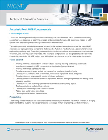
Autodesk Civil 3D 2022: Fundamentals The Display tab defines which figure’s components displayand which layers they use for plan, model, profile, andsection views, as shown in Figure 2–1.Figure 2–1Figure PrefixDatabaseThe Figure Prefix database (found in the Toolspace, Survey tab)assigns the figure a style, a layer, and defines whether the figureis a surface breakline and/or lot line (parcel segment). If you didnot define any figure styles, you should at least assign a layer tocorrectly place the figure in the drawing. Toggling on theBreakline property, as shown in Figure 2–2, enables you selectall of the tagged survey figures and assign them to a surfacewithout having to insert or select from a drawing. Toggling on theLot Line property creates a parcel segment from the figure in thedrawing and, if there is a closed polygon or intersecting lines toform an enclosure, assigns a parcel label and creates a parcel inthe designated site.Figure 2–22–4 2021, ASCENT - Center for Technical Knowledge
Survey, Points, and LineworkIf the Name is EOP (as shown in Figure 2–2), any figure startingwith EOP uses these settings. This is similar to using aDescription Key Set, except that the entry in the Figure Prefixdatabase does not need an asterisk (*). The entry Namematches EOP-R or EOP-West or EOP-Main-East. Wheninserting survey figures in the drawing, Survey checks the FigurePrefix database for style or layer values. 2021, ASCENT - Center for Technical Knowledge 2–5
Autodesk Civil 3D 2022: FundamentalsPractice 2aCreating Figure PrefixesPractice Objective Create a figure database for automatically stylizing linework whenimporting field book or ASCII files.1. Open SUV1-A.dwg from the C:\Civil 3D Projects\Working\Survey folder.You might have tochange the draw orderof the image to be ableto view other objects. InModel Space, select theimage, right-click, andselect DisplayOrder Send to Back.2. In the Toolspace, select the Survey tab. Right-click on FigurePrefix Databases, and select New . Type ASCENT for thename.3. Right-click on the newly created ASCENT Figure Prefixdatabase, and select Make Current.4. Right-click on the ASCENT Figure Prefix database again,and select Manage Figure Prefix Database .5. Clickto create a new Figure definition. Set the followingoptions, as shown in Figure 2–3: Change the Name to TRAIL.Select Breakline.Set Style to ASC-Road Centerline.Any figure starting with TRAIL will now be selectable for asurface breakline and will use the style ASC-RoadCenterline. As noted earlier, unlike the Description Key Set,an asterisk (*) is not necessary to match Trail1, Trail2, etc.Figure 2–36. Clickto create a new Figure definition. Change the name to BLDG. Set the Breakline to No. Set the Style to ASC-Buildings.7. Click OK to exit the dialog box.8. Save the drawing.2–6 2021, ASCENT - Center for Technical Knowledge
Survey, Points, and Linework2.3 StylesStyles are preconfigured groups of settings (specific to anindividual object type or label) that make the objects display andprint the way you want them to. For example, in the list of surfacestyles shown in Figure 2–4, each surface style is configureddifferently to display different features, such as contours atdifferent intervals and on the correct layers. The display of aterrain model could be changed by swapping one surface stylefor another. Styles enable an organization to standardize thelook of their graphics by providing preconfigured groupings ofdisplay settings.Figure 2–4The two categories of styles you work with most often are ObjectStyles and Label Styles. Some objects have table styles as well.Object styles control how Autodesk Civil 3D objects (points,surfaces, alignments, etc.) display, what combination ofcomponents the object displays, which layers they display on,and many other settings. Label Styles are similar except thatthey control the text and other annotations associated with theobjects. 2021, ASCENT - Center for Technical Knowledge 2–7
Autodesk Civil 3D 2022: FundamentalsFor example, an alignment object style specifies many settingsincluding the layers on which to draw tangents and curvesegments (which might be different) and the symbols to add atcertain points as required (such as a triangle at the PI point).Alignment label styles include major and minor station labels, thedisplay of station equations, design speeds, and similarannotation. By separating object and label styles, you can mixand match the right combination for a specific object.Styles are the lowest items in the Toolspace, Settings tree andare typically dependent on other settings above them. If a style isgiven a unique setting, different from feature settings or labelstyle defaults (such as a different text height), then that style isconsidered to have an override.Label StylesLabel styles produce annotation of values from existingconditions or a design solution. A label annotates a contour’selevations, a parcel’s number and area, a horizontal geometrypoint’s station on an alignment, etc.A label style can have text, vectors, AutoCAD blocks, andreference text. The content of a label depends on the selectedobject’s components or properties. For instance, a Line label canannotate bearing, distance, and coordinates, and use a directionarrow. A Parcel Area label can contain a parcel’s area, perimeter,address, and other pertinent values. A surface label can includea spot elevation, reference for an alignment’s station and offset,or other pertinent surface information.2–8 To access the values of a label style, in the Toolspace,Settings tab, select the style, right-click on its name, andselect Edit. A style’s initial values come from Edit Label Style Defaultsand the style’s definition. All labels use the same interface. The object properties available for each label vary by objecttype. 2021, ASCENT - Center for Technical Knowledge
Survey, Points, and LineworkEach label style uses the same tabbed dialog box. TheInformation tab describes the style as well as who defined andlast modified its contents. The values of the General tab affect alloccurrences of the label in a drawing. For example, if Visibility isset to False, all labels of this style are hidden in the drawing.Other settings affect the label’s text style, initial orientation, andreaction to a rotated view.The Layout tab lists all of a label’s components. A labelcomponent can be text, line, block, or tick. The Componentname drop-down list (shown in Figure 2–5), contains all of thedefined components for the style. When selecting a componentname in the drop-down list, the panel displays information aboutthe component’s anchoring, justification, format, and border.Figure 2–5 2021, ASCENT - Center for Technical Knowledge 2–9
Autodesk Civil 3D 2022: FundamentalsWhen defining a new text component, you assign it an objectproperty by clicking(Browse) for Contents. This opens theText Component Editor dialog box, as shown in Figure 2–6. TheProperties drop-down list displays the available objectproperties. The number and types of properties varies by objecttype. For example, a parcel area label has more and differentproperties than a line label does. Once a property has beenselected, units, precision, and other settings can be set todisplay the property correctly in the label. Clicknext toProperties to place the property in the label layout area to theright.Figure 2–62–10 2021, ASCENT - Center for Technical Knowledge
Survey, Points, and LineworkThe values in the Dragged State tab define a label’s behaviorwhen it is dragged to a new location in the drawing.The key to having the label display correctly when it is not in thedragged state, is to line up the Anchor Point of the componentwith the Attachment option for the text. Each has nine optionsfrom which to select. The options are shown in Figure 2–7.Figure 2–7Lining up the square hatched Anchor Point with the circularhatched attachment option results in the text centered above theobject similar to the bearing distance label shown in Figure 2–8.Figure 2–8 2021, ASCENT - Center for Technical Knowledge 2–11
Autodesk Civil 3D 2022: Fundamentals2.4 Points OverviewSurvey Points are often used at the beginning of a project andCOGO Points (for stakeout) at the end of a project. Surveyorscollect data about existing site conditions (elevations, utilities,ownership, etc.) for the project. Their world is coordinates, whichare represented by points. Each point has a unique number (orname) and a label containing additional information (usually theelevation of the coordinate and a short coded description).There are no national standards for point descriptions in theSurveying industry. Each company or survey crew needs to workout its own conventions. There are no standards for symbolseither. Each firm can have its own set of symbols. The symbolsused in a submission set can be specified by the firm contractingthe services.Autodesk Civil 3D cogo / survey points are a single object withtwo elements: a point style and a point label style. A cogo /survey point definition is shown in Figure 2–9.Figure 2–9The following is important point information: A point style (no matter what it displays), an AutoCAD node,a custom marker, or a block is selectable with an AutoCADNode object snap.A point label is not limited to the point’s number, elevation, anddescription. A point label can contain lines, blocks, and otherpoint properties. One can set up User-Defined point propertiesas well. For example, point labels might only display an elevationor description. This text can be manually overridden (as shown inFigure 2–10) or it can consist of intelligent variables thatrepresent point characteristics (such as its convergence angle).2–12 2021, ASCENT - Center for Technical Knowledge
Survey, Points, and LineworkIn assigned coordinate systems, the convergence angle is thedifference between a geodetic azimuth and the projection of thatazimuth onto a grid (grid azimuth) of a given point.Figure 2–10Point Marker StylesA surveyor interacts with points daily. To easily use AutodeskCivil 3D points, you need to have a basic understanding of theirrelated styles.The Autodesk Civil 3D software provides metric and imperialtemplate files that contain several point styles: Autodesk Civil 3DImperial (NCS) and Autodesk Civil 3D Metric (NCS). These twotemplates use the National CAD standards for their layers andprovide examples of styles that you can use in a project. Tocustomize these styles, you need to modify and expand the listof point styles.Customizing styles needs to be managed carefully. Consult withyour BIM Manager as to the standards and procedures for suchcustomization. If you do modify an existing style or create a newone, be sure to put your name or initials in the Created by: fieldfor easy identification, as shown Figure 2–11.Figure 2–11When installing the Autodesk Civil 3D software, the first thingyou should do is set one of these two templates as your defaulttemplate. Alternatively, your BIM Manager can develop styles tobe used in your organization’s drawing template file. 2021, ASCENT - Center for Technical Knowledge 2–13
Autodesk Civil 3D 2022: FundamentalsA point style defines a point’s display, its 3D elevation, and itscoordinate marker size. In the example shown in Figure 2–12,the point style is an X for a ground shot.Figure 2–12The Point Style dialog box has five tabs: Information, Marker, 3DGeometry, Display, and Summary.The Information tab sets the point style’s name and description,as shown in Figure 2–13.Figure 2–13The Marker tab supports three marker definition methods, asshown in Figure 2–14.2–14 2021, ASCENT - Center for Technical Knowledge
Survey, Points, and LineworkFigure 2–14 Use AutoCAD POINT [node] for marker: All points in thedrawing follow AutoCAD’s PDMODE and PDSIZE systemvariables. You do not have independent control over pointsusing this option. (This option is seldom used.) Use custom marker: This option creates markers similar toan AutoCAD point (node). However, the marker is under theAutodesk Civil 3D software’s control, and each point style candisplay a different combination of marker styles. When usingthis option, select the components of the style from the list ofCustom marker style shapes. A custom marker can haveshapes from the left and right sides. The first comes from oneof the five icons on the style’s left side, and you can optionallyadd none, one, or both shapes from the right. Use AutoCAD BLOCK symbol for marker: This optiondefines the marker using a block (symbol). The blocks listedrepresent definitions in the drawing. When the cursor is in thisarea and you right-click, you can browse to a locationcontaining drawings that you want to include as pointmarkers. 2021, ASCENT - Center for Technical Knowledge 2–15
Autodesk Civil 3D 2022: FundamentalsOptions for scaling the marker display in the marker panel’s topright corner. The most common option is Use drawing scale (asshown in Figure 2–15), which takes the marker size (0.1000")and multiplies it by the current drawing’s annotation scale,resulting in the final marker size. When the annotation scalechanges, the Autodesk Civil 3D software automatically resizesthe markers and their labels to be the appropriate size for thescale.Figure 2–15The other options are described as follows:Use fixed scaleSpecifies user-defined X, Y, and Z scale values.Use size inabsolute unitsSpecifies a user-defined size.Use size relativeto screenSpecifies a user-defined percentage of the screen.The 3D Geometry tab affects the point’s elevation. The defaultoption is Use Point Elevation (as shown in Figure 2–16), whichdisplays the point at its actual elevation value.Figure 2–162–16 2021, ASCENT - Center for Technical Knowledge
Survey, Points, and LineworkThe other options are described as follows:Flatten Points toElevationSpecifies the elevation to which the point is projected(flattened). The Point Elevation cell highlights if thisoption is selected and is 0 elevation by default.When using an AutoCAD object snap to select amarker using this option, the resulting entity’selevation is the default elevation of 0. If selecting bypoint number or point object, the resulting entity isthe point’s actual elevation.Exaggerate Pointsby Scale FactorExaggerates the point’s elevation by a specifiedscale factor. When selecting this option, the ScaleFactor cell highlights.The Display tab assigns the marker and label layers, and setstheir visibility and properties. Setting the property to ByLayeruses the layer’s properties. Alternatively, you can override theoriginal layer properties by setting a specific color, linetype, orlineweight.A style’s view direction value affects how the point and labelcomponents display in the plan, model, profile, and sectionviews, as shown in Figure 2–17.Figure 2–17The Summary tab is a report of all of the style’s settings.Controlling a leader arrow from a label in the dragged state,points to the boundary of the marker (yes) or the center of themarker (no). It is also changed under Marker Leader and stopsat marker. You can also edit style variables in this tab. 2021, ASCENT - Center for Technical Knowledge 2–17
Autodesk Civil 3D 2022: FundamentalsPoint LabelStyleThe Autodesk Civil 3D point label style annotates point propertiesbeyond the typical point number, elevation and description. Atypical point label style is shown in Figure 2–18.Figure 2–18All Autodesk Civil 3D label style dialog boxes are the same. Thebasic behaviors for a label are in the settings in the Edit LabelStyle Defaults dialog box. The values in this dialog box define thelabel layer, text style, orientation, plan readability, size, draggedstate behaviors, etc.In the Toolspace, Settings tab, the drawing name and objectcollections control these values for the entire drawing (at thedrawing name level) or for the selected collection (Surface,Alignment, Point, etc.) To open the Edit Label Style Defaults dialogbox, select the drawing name or a heading, right-click, and selectEdit Label Style Defaults , as shown in Figure 2–19.Figure 2–192–18 2021, ASCENT - Center for Technical Knowledge
Survey, Points, and LineworkThe Label Style Composer dialog box contains five tabs, eachdefining specific label behaviors: Information, General, Layout,Dragged State, and Summary.The Information tab names the style, as shown in Figure 2–20.Figure 2–20The General tab contains three properties: Label (text style andlayer), Behavior (orientation), and Plan Readability (amount ofview rotation before flipping text to read from the bottom or theright side of the sheet), as shown in Figure 2–21.Figure 2–21The Label property sets the Text Style, Label Visibility, Layer.Select the Value cell next to the Text Style and Layer to openbrowsers and change their values. Selecting the Label Visibilitycell displays a drop-down list containing the options true andfalse. 2021, ASCENT - Center for Technical Knowledge 2–19
Autodesk Civil 3D 2022: FundamentalsThe Behavior property sets two variables that control the label’slocation. The Orientation Reference variable contains the threelabel orientation options.ObjectRotates labels relative to the object’s zero direction. Theobject’s zero direction is based on its start to end vector. Ifthe vector changes at the label’s anchor point, theorientation updates automatically. This is the default setting.ViewForces labels to realign relative to a screen-view orientationin both model and layout views. This method assumes thatthe zero angle is horizontal, regardless of the UCS or Dviewtwist. If the view changes, the label orientation updates aswell.WorldCoordinateSystemLabels read left to right using the WCS X-axis. Changing theview or current UCS does not affect label rotation. The labelalways references the world coordinate system.Under the Behavior property, the Forced Insertion variable hasthree optional values that specify the label’s position relative toan object. This setting only applies when the OrientationReference is set to Object and the objects are lines, arcs, orspline segments. NoneMaintains label position as composed relative to the object.TopAdjusts label position to be above an object.BottomAdjusts label position to be below an object.Note: If you select Top or Bottom, set the value of PlanReadable to True.The Plan Readability property has three variables that affect howtext flips when rotating a drawing view.Under the Plan Readability property, the Plan Readable variablehas two options.TrueEnables text to rotate to maintain left to right readability fromthe bottom or right side of the drawing.FalseDoes not permit text to flip. The resulting text might beupside down or read from right to left.The Readability Bias variable is the amount of rotation requiredto flip a label to become left to right readable. The angle ismeasured counter-clockwise from the WCS 0 (zero) direction.2–20 2021, ASCENT - Center for Technical Knowledge
Survey, Points, and LineworkThe Flip Anchors with Text variable has two options:TrueIf the text flips, the text anchor point also flips.FalseThe label flips, but maintains the original anchor point. Thebehavior is similar to mirroring the original text.The Layout tab defines the label contents, as shown inFigure 2–22. A label component is an object property that itlabels. Point properties include northing, easting, rawdescription, etc. If User Defined properties are in use, they willalso be available. A label might have one component withseveral properties or several components each containing anobject property, as well as regular text (such as Northing:).Figure 2–22A point style label component can be text, lines, or blocks. Otherobject type label styles can include additional components, suchas reference text, ticks, directional arrows, etc. To add acomponent, expand the drop-down list (as shown inFigure 2–23) and select the component type.Figure 2–23 2021, ASCENT - Center for Technical Knowledge 2–21
Autodesk Civil 3D 2022: FundamentalsThe remaining icons in the Layout tab are described as follows:Copies the current component and its properties.Deletes the current component.Changes the display order of a label’s components. For example,use this icon to change the draw order of the label’s componentsuch as text above a mask.Depending on the label component type, it might have anycombination of three areas: General, Text, and Border. Generaldefines how the label attaches to the object or other labelcomponents, its visibility, and its anchor point.If the label component is text, the Text property values affect howit displays its object property. To set or modify a label’s textvalue, select the cell next to Contents to display(shown inFigure 2–24). Clickto open the Text Component Editor dialogbox.Figure 2–24The Text Component Editor dialog box (shown in Figure 2–25),defines the properties that the label annotates. When creating alabel component, double-click on the text in the right pane tohighlight it. In the left pane, select the property that you want toadd, set the property’s format values, and then clickthe new property to the label component.2–22to add 2021, ASCENT - Center for Technical Knowledge
Survey, Points, and LineworkFigure 2–25It is important to maintain the process order and to rememberthat the text on the right in brackets needs to be highlightedbefore you can revise its format values on the left.The Dragged State tab has two properties: Leader and DraggedState Components. This tab defines how a label behaves whenyou are dragging a label from its original insertion point.The Leader property defines whether a leader displays and whatproperties it displays. You can use the label’s layer properties inthe General tab (ByLayer) or override them by specifying acolor, as shown in Figure 2–26.Figure 2–26 2021, ASCENT - Center for Technical Knowledge 2–23
Autodesk Civil 3D 2022: FundamentalsThe Dragged State Components property defines the labelcomponent’s display after it has been dragged from its originalposition. Select the cell next to Display to view the two displayoptions, as shown in Figure 2–27.Figure 2–27AsComposedThe label maintains its original definition and orientationfrom the settings in the Layout panel. When you select AsComposed, all of the other values become unavailable forediting.Stacked TextThe label text becomes left justified and label componentsare stacked in the order listed in Layout’s ComponentName list. When you select Stacked Text, all of theblocks, lines, ticks, and direction arrows are removed.The Summary tab lists the label component, general, anddragged state values for the label style. The label componentsare listed numerically in the order in which they were defined andreport all of the current values.2–24 2021, ASCENT - Center for Technical Knowledge
Survey, Points, and LineworkPractice 2bPoint Marker StylesPractice Objective Create a point marker and label style to ensure that the correct symbolis assigned to specific points.In this practice, you will create a new point style and apply it toan existing group of points.Task 1 - Add a block symbol.1. Continue working on the drawing from the previous practiceor open SUV1-B1-Survey-.dwg from the C:\Civil 3DProjects\Working\Survey folder.The aerial image usedin this chapter wasattached using theAutoCAD Map 3DFDO connection.2. To toggle off the aerial image, in the Home tab Palettespanel, clickON.(Map Task Pane). When prompted, select3. In the Task pane Display Manager tab, clear the Main SiteImperial layer, as shown in Figure 2–28. Select Map Baseagain to clear the Raster Layer contextual tab. Close the mapTask Pane.Figure 2–284. In the Toolspace, Settings tab, expand the Point collectionuntil Point Styles displays. Expand the Point Styles collection.Review the Point Styleslist and note that there isno light pole style.5. In the Point Styles list, select the ASC-Guy pole style,right-click, and select Copy . 2021, ASCENT - Center for Technical Knowledge 2–25
Autodesk Civil 3D 2022: Fundamentals6. In the Information tab, change the point style’s name toASC-Light Pole and enter your name or initials in theCreated by: field.7. Select the Marker tab. Select the Use AutoCAD BLOCKsymbol for marker option. In the block list, scroll across asrequired and select the AutoCAD block ST-Light, as shownin Figure 2–29.Figure 2–298. Select the Display tab and note that the layer settings arefrom the Guy Pole point style.9. You can reassign the marker and/or label layer by selectingthe layer name. Select the l
with the Autodesk Civil 3D software. If following the Linework Code Set command format, you do not need to convert the coordinate file to a field book. The Autodesk Civil 3D software needs to have all of the necessary Styles, Settings, and Figure Prefixes to create, so