Transcription
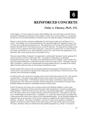
Development of Tsunami Design Provisions forthe ASCE/SEI 7-16 StandardIan N. Robertson, S.E., ianrob@hawaii.eduProfessor of Structural Engineering, UH ManoaMichael Mahoney, mike.mahoney@fema.dhs.govSenior Geophysicist, Federal Emergency Management AgencyTohoku Tsunami photograph at Minami Soma by Sadatsugu Tomizawa
ASCE/SEI 7-10 Minimum Design Loads forBuildings and Other Structuresby American Society of CivilEngineers’ (ASCE) StructuralEngineering Institute (SEI). Consensus design standardupdated every 5 years usingANSI-approved process. ASCE/SEI 7-10 is adopted byreference by the 2012 and 2015International Building Codes(IBC), and therefore most USjurisdictions.
ASCE/SEI 7-10Minimum Design Loads for Buildings and OtherStructures Chap 1 & 2 – General and load combinations Chap 3 - Dead, soil and hydrostatic loads Chap 4 - Live loads Chap 5 - Flood loads (riverine and storm surge) Chap 6 - Vacant Chap 7 - Snow loads Chap 8 - Rain loads Chap 10 - Ice loads Chap 11 – 23 - Seismic Design Chap 26 – 31 - Wind Loads
ASCE/SEI 7-10Minimum Design Loads for Buildings and OtherStructures Chap 1 & 2 – General and load combinations Chap 3 - Dead, soil and hydrostatic loads Chap 4 - Live loads Chap 5 - Flood loads (riverine and storm surge) Chap 6 - Vacant Chap 7 - Snow loads Chap 8 - Rain loads Chap 10 - Ice loads Chap 11 – 23 - Seismic Design Chap 26 – 31 - Wind Loads
ASCE/SEI 7-16Minimum Design Loads for Buildings and OtherStructures Chap 1 & 2 – General and load combinations Chap 3 - Dead, soil and hydrostatic loads Chap 4 - Live loads Chap 5 - Flood loads (riverine and storm surge) Chap 6 – Tsunami Loads and Effects Chap 7 - Snow loads Chap 8 - Rain loads Chap 10 - Ice loads Chap 11 – 23 - Seismic Design Chap 26 – 31 - Wind Loads
ASCE/SEI 7 Tsunami Loads and Effects Subcommittee of 16 members and 14 associatemembers formed in February 2011.– One month before Tohoku tsunami. Subcommittee met 4-5 times per year for three years. Processed 8 consensus ballots through ASCE/SEI 7-16Main Committee, addressing over 1500 comments. Final version issued for public comment in Fall 2015. Officially approved for ASCE/SEI 7-16 March 11, 2016. ASCE/SEI 7-16 accepted by International Code Councilfor inclusion in IBC 2018 in December 2017. ASCE/SEI will also be publishing a companion designguide in late 2017 with numerous design examples.
Tsunami-Resilient Engineering Subject MatterIncorporated in ASCE 7Scope ofASCE/SEI 7Chapter 6Sources and FrequencyConsensus onSeismic SourceAssessment by USGSTsunami GenerationDistant and Local Subduction ZonesTsunamiInundationModeling toDefineTsunamiDesign ZonesLoads l, andGeotechnicalEngineeringOpen Ocean PropagationOffshore Tsunami AmplitudeMaps based onProbabilisticTsunami HazardAnalysis (PTHA)Coastal Inundation and FlowVelocitiesFluid-Structure InteractionStructural LoadingStructural ResponseScour and ErosionPerformance by RiskCategoryConsequences(Life and economic losses)Warning and Societal ImpactAssessment forthe Five WesternStates by USGS
ASCE 7 Chapter 6- Tsunami Loads and Effects 6.1 General Requirements6.2-6.3 Definitions, Symbols and Notation6.4 Tsunami Risk Categories6.5 Analysis of Design Inundation Depth and Velocity6.6 Inundation Depth and Flow Velocity Based on Runup6.7 Inundation Depth and Flow Velocity Based on Site-SpecificProbabilistic Tsunami Hazard Analysis6.8 Structural Design Procedures for Tsunami Effects6.9 Hydrostatic Loads6.10 Hydrodynamic Loads6.11 Debris Impact Loads6.12 Foundation Design6.13 Structural Countermeasures for Tsunami Loading6.14 Tsunami Vertical Evacuation Refuge Structures6.15 Designated Nonstructural Systems6.16 Non-Building Structures
ASCE 7 Chapter 6- Tsunami Loads and Effects 6.1 General Requirements6.2-6.3 Definitions, Symbols and Notation6.4 Tsunami Risk Categories6.5 Analysis of Design Inundation Depth and Velocity6.6 Inundation Depth and Flow Velocity Based on Runup6.7 Inundation Depth and Flow Velocity Based on Site-SpecificProbabilistic Tsunami Hazard Analysis6.8 Structural Design Procedures for Tsunami Effects6.9 Hydrostatic Loads6.10 Hydrodynamic Loads6.11 Debris Impact Loads6.12 Foundation Design6.13 Structural Countermeasures for Tsunami Loading6.14 Tsunami Vertical Evacuation Refuge Structures6.15 Designated Nonstructural Systems6.16 Non-Building Structures
MCT and Tsunami Design Zone ASCE 7 Tsunami Loads and Effects Chapter is applicableonly to the states of Alaska, Washington, Oregon,California, and Hawaii, which have quantifiable tsunamihazards. The Maximum Considered Tsunami (MCT) has a 2%probability of being exceeded in a 50-year period, or a 2500 year average return period. The MCT is the design basis event, characterized by theinundation depths and flow velocities at the stages ofin-flow and out-flow most critical to the structure. The Tsunami Design Zone is the area vulnerable tobeing flooded or inundated by the MaximumConsidered Tsunami.
Consequence Guidance on RiskCategories of Buildings Per ASCE/SEI 7Risk Category IUp to 2 persons affectedRisk Category II(Tsunami DesignOptional)Risk Category III(Tsunami DesignRequired)Approximately 3 to 300 persons affectedRisk Category IV(Tsunami DesignRequired)(e.g., agricultural and minor storage facilities, etc.)(e.g., Office buildings, condominiums, hotels, etc.)Approximately 300 to 5,000 affected(e.g., Public assembly halls, arenas, high occupancy educationalfacilities, public utility facilities, etc.)Over 5,000 persons affected(e.g., hospitals and emergency shelters, emergency operationscenters, first responder facilities, air traffic control, toxic materialstorage, etc.)Visual 20.11
ASCE 7 Chapter 6- Tsunami Loads and Effects 6.1 General Requirements6.2-6.3 Definitions, Symbols and Notation6.4 Tsunami Risk Categories6.5 Analysis of Design Inundation Depth and Velocity6.6 Inundation Depth and Flow Velocity Based on Runup6.7 Inundation Depth and Flow Velocity Based on Site-SpecificProbabilistic Tsunami Hazard Analysis6.8 Structural Design Procedures for Tsunami Effects6.9 Hydrostatic Loads6.10 Hydrodynamic Loads6.11 Debris Impact Loads6.12 Foundation Design6.13 Structural Countermeasures for Tsunami Loading6.14 Tsunami Vertical Evacuation Refuge Structures6.15 Designated Nonstructural Systems6.16 Non-Building Structures
PTHA Derived MCT Probabilistic hazard identification required in order to be in the model code. The ASCE PTHA procedure was peer reviewed by NTHMP stakeholder group. Subduction Zone Earthquake Sources are consistent with USGS ProbabilisticSeismic Hazard model.
ASCE 7 Chapter 6- Tsunami Loads and Effects 6.1 General Requirements6.2-6.3 Definitions, Symbols and Notation6.4 Tsunami Risk Categories6.5 Analysis of Design Inundation Depth and Velocity6.6 Inundation Depth and Flow Velocity Based on Runup6.7 Inundation Depth and Flow Velocity Based on Site-SpecificProbabilistic Tsunami Hazard Analysis6.8 Structural Design Procedures for Tsunami Effects6.9 Hydrostatic Loads6.10 Hydrodynamic Loads6.11 Debris Impact Loads6.12 Foundation Design6.13 Structural Countermeasures for Tsunami Loading6.14 Tsunami Vertical Evacuation Refuge Structures6.15 Designated Nonstructural Systems6.16 Non-Building Structures
Tsunami Flow CharacteristicsTwo approaches to determine flow depth and velocity Energy Grade Line Analysis method based on precalculated runup from the Tsunami Design Zonemaps– Required for all TRC III and IV buildings Site-Specific Probabilistic Hazard Analysis– Required for TRC IV buildings– Optional for other TRCs– Velocity lower limit of 75-90% EGL method
ASCE 7 Chapter 6- Tsunami Loads and Effects 6.1 General Requirements6.2-6.3 Definitions, Symbols and Notation6.4 Tsunami Risk Categories6.5 Analysis of Design Inundation Depth and Velocity6.6 Inundation Depth and Flow Velocity Based on Runup6.7 Inundation Depth and Flow Velocity Based on Site-SpecificProbabilistic Tsunami Hazard Analysis6.8 Structural Design Procedures for Tsunami Effects6.9 Hydrostatic Loads6.10 Hydrodynamic Loads6.11 Debris Impact Loads6.12 Foundation Design6.13 Structural Countermeasures for Tsunami Loading6.14 Tsunami Vertical Evacuation Refuge Structures6.15 Designated Nonstructural Systems6.16 Non-Building Structures
ASCE 7 Chapter 6- Tsunami Loads and Effects 6.1 General Requirements6.2-6.3 Definitions, Symbols and Notation6.4 Tsunami Risk Categories6.5 Analysis of Design Inundation Depth and Velocity6.6 Inundation Depth and Flow Velocity Based on Runup6.7 Inundation Depth and Flow Velocity Based on Site-SpecificProbabilistic Tsunami Hazard Analysis6.8 Structural Design Procedures for Tsunami Effects6.9 Hydrostatic Loads6.10 Hydrodynamic Loads6.11 Debris Impact Loads6.12 Foundation Design6.13 Structural Countermeasures for Tsunami Loading6.14 Tsunami Vertical Evacuation Refuge Structures6.15 Designated Nonstructural Systems6.16 Non-Building Structures
Tsunami Load Conditions Hydrostatic Forces (equations of the form ksρswgh)– Unbalanced Lateral Forces at initial flooding– Buoyant Uplift based on displaced volume– Residual Water Surcharge Loads on Elevated Floors Hydrodynamic Forces (equations of the form ½ ksρsw(hu2)––––Drag Forces – per drag coefficient Cd based on size and elementLateral Impulsive Forces of Tsunami Bores on Broad Walls: Factor of 1.5Hydrodynamic Pressurization by Stagnated Flow – per BenoulliShock pressure effect of entrapped bore Waterborne Debris Impact Forces (flow speed and k m)– Poles, passenger vehicles, medium boulders always applied– Shipping containers, boats if structure is in proximity to hazard zone– Extraordinary impacts of ships only where in proximity to Risk Category III& IV structures
ASCE 7 Chapter 6- Tsunami Loads and Effects 6.1 General Requirements6.2-6.3 Definitions, Symbols and Notation6.4 Tsunami Risk Categories6.5 Analysis of Design Inundation Depth and Velocity6.6 Inundation Depth and Flow Velocity Based on Runup6.7 Inundation Depth and Flow Velocity Based on Site-SpecificProbabilistic Tsunami Hazard Analysis6.8 Structural Design Procedures for Tsunami Effects6.9 Hydrostatic Loads6.10 Hydrodynamic Loads6.11 Debris Impact Loads6.12 Foundation Design6.13 Structural Countermeasures for Tsunami Loading6.14 Tsunami Vertical Evacuation Refuge Structures6.15 Designated Nonstructural Systems6.16 Non-Building Structures
ASCE 7 Chapter 6- Tsunami Loads and Effects 6.1 General Requirements6.2-6.3 Definitions, Symbols and Notation6.4 Tsunami Risk Categories6.5 Analysis of Design Inundation Depth and Velocity6.6 Inundation Depth and Flow Velocity Based on Runup6.7 Inundation Depth and Flow Velocity Based on Site-SpecificProbabilistic Tsunami Hazard Analysis6.8 Structural Design Procedures for Tsunami Effects6.9 Hydrostatic Loads6.10 Hydrodynamic Loads6.11 Debris Impact Loads6.12 Foundation Design6.13 Structural Countermeasures for Tsunami Loading6.14 Tsunami Vertical Evacuation Refuge Structures6.15 Designated Nonstructural Systems6.16 Non-Building Structures
Tsunami Vertical Evacuation Refuge Structures Tsunami Vertical Evacuation Refuge Structures - ASCE 7 Chapter6 is intended to supersede both FEMA P646 structural guidelinesand IBC Appendix M Additional reliability (99%) is achieved through site-specificinundation analysis and an increase in the design inundationelevationFigure 6.14-1. Minimum Refuge Elevation21
ASCE 7 Chapter 6- Tsunami Loads and Effects 6.1 General Requirements6.2-6.3 Definitions, Symbols and Notation6.4 Tsunami Risk Categories6.5 Analysis of Design Inundation Depth and Velocity6.6 Inundation Depth and Flow Velocity Based on Runup6.7 Inundation Depth and Flow Velocity Based on Site-SpecificProbabilistic Tsunami Hazard Analysis6.8 Structural Design Procedures for Tsunami Effects6.9 Hydrostatic Loads6.10 Hydrodynamic Loads6.11 Debris Impact Loads6.12 Foundation Design6.13 Structural Countermeasures for Tsunami Loading6.14 Tsunami Vertical Evacuation Refuge Structures6.15 Designated Nonstructural Systems6.16 Non-Building Structures
Summary ASCE/SEI 7 Chapter 6 provides a comprehensive method forreliable tsunami structural resilience, making tsunamis arequired consideration in planning, siting, and design ofcoastal structures in the five western states. Probabilistic Tsunami Hazard Analysis is the basis for thedevelopment of 2475-yr MRI Tsunami Design Zone maps. Specified design procedures are provided for all possibleloading conditions. Coastal communities are encouraged to require tsunamidesign for taller Risk Category II buildings to provide a greaternumber of buildings that will be disaster-resilient. ASCE/SEI 7-16 (and Chapter 6) still need to be adopted by the5 western States into their State building codes.
IBC Appendix M IBC Appendix M, Tsunami Generated Flood Hazard, wasoriginally submitted using the analysis and structural designaspects of FEMA P-646, Guidelines for Design of Structures forVertical Evacuation from Tsunamis. However, this much of the technical provisions have beensuperseded by Chapter 6 of ASCE/SEI 7-2016. A proposal to update Appendix M for the 2018 IBC wassubmitted by FEMA and ASCE so it now only refers to thetsunami evacuation and site planning criteria of FEMA P-646. It will now defer to the tsunami hazard mapping andstructural design guidelines of ASCE/SEI 7-16 Chapter 6. The title of Appendix M was also revised to focus only ontsunami vertical evacuation refuge structures.
APPENDIX M TSUNAMI-GENERATED FLOOD HAZARD SECTIONM101 REFUGE STRUCTURES FOR VERTICAL EVACUATION FROM TSUNAMIGENERATED FLOOD HAZARDM101.1 General. The purpose of this appendix is to provide tsunami verticalevacuation planning criteria for those coastal communities that have atsunami hazard as shown in a Tsunami Design Zone Map.M101.2 Definitions. The following words and terms shall, for the purposes ofthis appendix, have the meanings shown herein. Refer to Chapter 2 of thiscode for general definitions.TSUNAMI HAZARD DESIGN ZONE MAP.A map that designates the extent of inundation by a MaximumConsidered Tsunami as defined by ASCE 7-16 Standard.M101.3 Establishment of tsunami design zone. Where applicable, theTsunami Design Zone Map shall meet or exceed the inundation limit given bythe ASCE 7 Tsunami Design Geodatabase.M101.4 Planning of tsunami vertical evacuation refuge structures within thetsunami design zone. Tsunami Vertical Evacuation Refuge Structures locatedin a tsunami design zone shall be planned, sited and developed in generalaccordance with the planning criteria of FEMA P646-12.Exception: These criteria shall not be considered mandatory forevaluation of existing buildings for evacuation planning purposes.
FEMA P-646 Vertical Refuge Guide The April 2012 edition of FEMA P646contains information now in conflictwith ASCE/SEI 7-16 Chapter 6 and mustbe updated to remove those conflicts. Funding for a full update was notavailable from either NOAA/NTHMP orFEMA/NEHRP. A “low cost” update has been added toan existing task order and is currentlybeing performed by Ian Robertson. The final draft due this spring and willbe sent out for review; includingNTHMP MES State and territorialrepresentatives.Guidelines for Designof Structures for VerticalEvacuation From Tsunamis
Thank-YouQuestions?
ASCE/SEI 7-10 is the current standard for all loads used in the design of new buildings and other structures in the US. It is \൲eferenced by the International Building Code, IBC-2012, which is the official buildin