Transcription
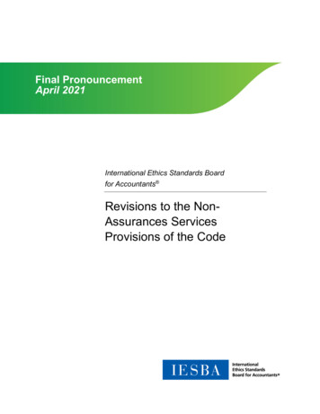
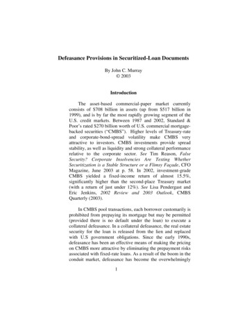
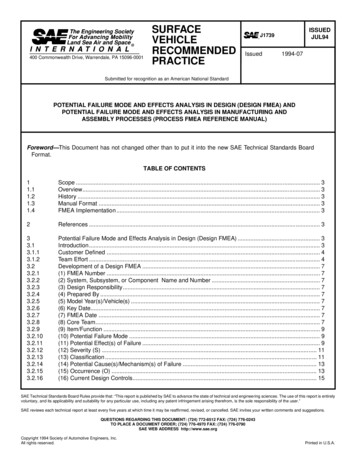
6REINFORCED CONCRETEFinley A. Charney, Ph.D., P.E.In this chapter, a 12-story reinforced concrete office building with some retail shops on the first floor isdesigned for both high and moderate seismic loadings. For the more extreme loading, it is assumed thatthe structure will be located in Berkeley, California, and for the moderate loading, in Honolulu, Hawaii.Figure 6-1 shows the basic structural configuration for each location in plan view and Figure 6-2, insection. The building, to be constructed primarily from sand-lightweight (LW) aggregate concrete, has12 stories above grade and one basement level. The typical bays are 30 ft long in the north-south (N-S)direction and either 40 ft or 20 ft long in the east-west (E-W) direction. The main gravity framing systemconsists of seven continuous 30-ft spans of pan joists. These joists are spaced 36 in. on center and havean average web thickness of 6 in. and a depth below slab of 16 in. Due to fire code requirements, a 4-in.thick floor slab is used, giving the joists a total depth of 20 in.The joists along Gridlines 2 through 7 are supported by variable depth "haunched" girders spanning 40 ftin the exterior bays and 20 ft in the interior bays. The girders are haunched to accommodatemechanical-electrical systems. The girders are not haunched on exterior Gridlines 1 and 8, and the 40-ftspans have been divided into two equal parts forming a total of five spans of 20 ft. The girders along allspans of Gridlines A and D are of constant depth, but along Gridlines B and C, the depth of the end baygirders has been reduced to allow for the passage of mechanical systems.Normal weight (NW) concrete walls are located around the entire perimeter of the basement level. NWconcrete also is used for the first (ground) floor framing and, as described later, for the lower levels of thestructural walls in the Berkeley building.For both locations, the seismic-force-resisting system in the N-S direction consists of four 7-bay momentresisting frames. The interior frames differ from the exterior frames only in the end bays where thegirders are of reduced depth. At the Berkeley location, these frames are detailed as special momentresisting frames. Due to the lower seismicity and lower demand for system ductility, the frames of theHonolulu building are detailed as intermediate moment-resisting frames.In the E-W direction, the seismic-force-resisting system for the Berkeley building is a dual systemcomposed of a combination of frames and frame-walls (walls integrated into a moment-resisting frame).Along Gridlines 1 and 8, the frames have five 20-ft bays with constant depth girders. Along Gridlines 2and 7, the frames consist of two exterior 40-ft bays and one 20-ft interior bay. The girders in each spanare of variable depth as described earlier. At Gridlines 3, 4, 5 and 6, the interior bay has been filled witha shear panel and the exterior bays consist of 40-ft-long haunched girders. For the Honolulu building, thestructural walls are not necessary so E-W seismic resistance is supplied by the moment frames alongGridlines 1 through 8. The frames on Gridlines 1 and 8 are five-bay frames and those on Gridlines 2through 7 are three-bay frames with the exterior bays having a 40-ft span and the interior bay having a20-ft span. Hereafter, frames are referred to by their gridline designation (e.g., Frame 1 is located on6-1
FEMA 451, NEHRP Recommended Provisions: Design ExamplesGridline 1). It is assumed that the structure for both the Berkeley and Honolulu locations is founded onvery dense soil (shear wave velocity of approximately 2000 ft/sec).''NFigure 6-2B7 at 30'-0"216'-0"Figure 6-2A5 at 20'-0"102'-6"Figure 6-1 Typical floor plan of the Berkeley building. The Honolulu building issimilar but without structural walls (1.0 ft 0.3048 m).6-2
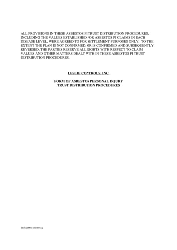
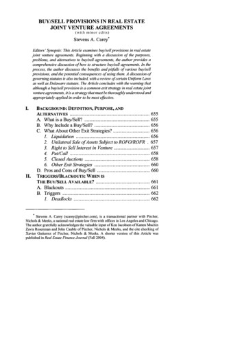
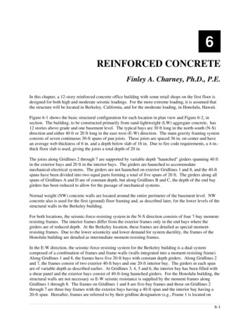
Chapter 6, Reinforced Concrete18'-0" 15'-0"B. Section at Frame40'-0"BA. Section at oryLevel20'-0"'G18'-0" 15'-0"11 at '-0"20'-0"'11 at 12'-6"Figure 6-2 Typical elevations of the Berkeley building; the Honolulu building issimilar but without structural walls (1.0 ft 0.3048 m).6-3
FEMA 451, NEHRP Recommended Provisions: Design ExamplesThe calculations herein are intended to provide a reference for the direct application of the designrequirements presented in the 2000 NEHRP Recommended Provisions (hereafter, the Provisions) and toassist the reader in developing a better understanding of the principles behind the Provisions.Because a single building configuration is designed for both high and moderate levels of seismicity, twodifferent sets of calculations are required. Instead of providing one full set of calculations for theBerkeley building and then another for the Honolulu building, portions of the calculations are presentedin parallel. For example, the development of seismic forces for the Berkeley and Honolulu buildings arepresented before structural design is considered for either building. The full design then is given for theBerkeley building followed by the design of the Honolulu building. Each major section (development offorces, structural design, etc.) is followed by discussion. In this context, the following portions of thedesign process are presented in varying amounts of detail for each structure:1. Development and computation of seismic forces;2. Structural analysis and interpretation of structural behavior;3. Design of structural members including typical girder in Frame 1, typical interior column in Frame 1,typical beam-column joint in Frame 1, typical girder in Frame 3, typical exterior column in Frame 3,typical beam-column joint in Frame 3, boundary elements of structural wall (Berkeley building only)and panel of structural wall (Berkeley building only).The design presented represents the first cycle of an iterative design process based on the equivalentlateral force (ELF) procedure according to Provisions Chapter 5. For final design, the Provisions mayrequire that a modal response spectrum analysis or time history analysis be used. The decision to usemore advanced analysis can not be made a priori because several calculations are required that cannot becompleted without a preliminary design. Hence, the preliminary design based on an ELF analysis is anatural place to start. The ELF analysis is useful even if the final design is based on a more sophisticatedanalysis (e.g., forces from an ELF analysis are used to apply accidental torsion and to scale the resultsfrom the more advanced analysis and are useful as a check on a modal response spectrum or time-historyanalysis).In addition to the Provisions, ACI 318 is the other main reference in this example. Except for very minorexceptions, the seismic-force-resisting system design requirements of ACI 318 have been adopted in theirentirety by the Provisions. Cases where requirements of the Provisions and ACI 318 differ are pointedout as they occur. ASCE 7 is cited when discussions involve live load reduction, wind load, and loadcombinations.Other recent works related to earthquake resistant design of reinforced concrete buildings include:ACI 318American Concrete Institute. 1999 [2002]. Building Code Requirements andCommentary for Structural Concrete.ASCE 7American Society of Civil Engineers. 1998 [2002]. Minimum Design Loads forBuildings and Other Structures.FanellaFanella, D.A., and M. Munshi. 1997. Design of Low-Rise Concrete Buildings forEarthquake Forces, 2nd Edition. Portland Cement Association, Skokie, Illinois.ACI 318 Notes Fanella, D.A., J. A. Munshi, and B. G. Rabbat, Editors. 1999. Notes on ACI 318-99Building Code Requirements for Structural Concrete with Design Applications. PortlandCement Association, Skokie, Illinois.6-4
Chapter 6, Reinforced ConcreteACI SP127Ghosh, S. K., Editor. 1991. Earthquake-Resistant Concrete Structures InelasticResponse and Design, ACI SP127. American Concrete Institute, Detroit, Michigan.GhoshGhosh, S. K., A. W. Domel, and D. A. Fanella. 1995. Design of Concrete Buildings forEarthquake and Wind Forces, 2nd Edition. Portland Cement Association, Skokie, Illinois.PaulayPaulay, T., and M. J. N. Priestley. 1992. Seismic Design of Reinforced Concrete andMasonry Buildings. John Wiley & Sons, New York.The Portland Cement Association’s notes on ACI 318 contain an excellent discussion of the principlesbehind the ACI 318 design requirements and an example of the design and detailing of a frame-wallstructure. The notes are based on the requirements of the 1997 Uniform Building Code (InternationalConference of Building Officials) instead of the Provisions. The other publications cited above provideadditional background for the design of earthquake-resistant reinforced concrete structures.Most of the large-scale structural analysis for this chapter was carried out using the ETABS BuildingAnalysis Program developed by Computers and Structures, Inc., Berkeley, California. Smaller portionsof the structure were modeled using the SAP2000 Finite Element Analysis Program, also developed byComputers and Structures. Column capacity and design curves were computed using Microsoft Excel,with some verification using the PCACOL program created and developed by the Portland CementAssociation.Although this volume of design examples is based on the 2000 Provisions, it has been annotated to reflectchanges made to the 2003 Provisions. Annotations within brackets, [ ], indicate both organizationalchanges (as a result of a reformat of all of the chapters of the 2003 Provisions) and substantive technicalchanges to the 2003 Provisions and its primary reference documents. While the general concepts of thechanges are described, the design examples and calculations have not been revised to reflect the changesto the 2003 Provisions.The changes related to reinforced concrete in Chapter 9 of the 2003 Provisions are generally intended tomaintaining compatibility between the Provisions and the ACI 318-02. Portions of the 2000 Provisionshave been removed because they were incorporated into ACI 318-02. Other chances to Chapter 9 arerelated to precast concrete (as discussed in Chapter 7 of this volume of design examples).Some general technical changes in the 2003 Provisions that relate to the calculations and/or design in thischapter include updated seismic hazard maps, revisions to the redundancy requirements, revisions to theminimum base shear equation, and revisions several of the system factors (R, Ω0, Cd) for dual systems.Where they affect the design examples in this chapter, other significant changes to the 2003 Provisionsand primary reference documents are noted. However, some minor changes to the 2003 Provisions andthe reference documents may not be noted.Note that these examples illustrate comparisons between seismic and wind loading for illustrativepurposes. Wind load calculations are based on ASCE 7-98 as referenced in the 2000 Provisions, andthere have not been any comparisons or annotations related to ASCE 7-02.6-5
FEMA 451, NEHRP Recommended Provisions: Design Examples6.1 DEVELOPMENT OF SEISMIC LOADS AND DESIGN REQUIREMENTS6.1.1 SeismicityUsing Provisions Maps 7 and 8 [Figures 3.3-3 and 3.3-4] for Berkeley, California, the short period andone-second period spectral response acceleration parameters SS and S1 are 1.65 and 0.68, respectively.[The 2003 Provisions have adopted the 2002 USGS probabilistic seismic hazard maps, and the maps havebeen added to the body of the 2003 Provisions as figures in Chapter 3 (instead of the previously usedseparate map package.] For the very dense soil conditions, Site Class C is appropriate as described inProvisions Sec. 4.1.2.1 [3.5.1]. Using SS 1.65 and Site Class C, Provisions Table 4.1.2.4a [3.3-1] lists ashort period site coefficient Fa of 1.0. For S1 0.5 and Site Class C, Provisions Table 4.1.2.4b [3.3-2]gives a velocity based site coefficient Fv of 1.3. Using Provisions Eq. 4.1.2.4-1 and 4.1.2.4-2 [3.3-1 and3.3-2], the maximum considered spectral response acceleration parameters for the Berkeley building are:SMS FaSS 1.0 x 1.65 1.65SM1 FvS1 1.3 x 0.68 0.884The design spectral response acceleration parameters are given by Provisions Eq. 4.1.2.5-1 and 4.1.2.5-2[3.3-3 and 3.3-4]:SDS (2/3) SMS (2/3) 1.65 1.10SD1 (2/3) SM1 (2/3) 0.884 0.589The transition period (Ts) for the Berkeley response spectrum is:Ts S D1 0.589 0.535 secS DS1.10Ts is the period where the horizontal (constant acceleration) portion of the design response spectrumintersects the descending (constant velocity or acceleration inversely proportional to T) portion of thespectrum. It is used later in this example as a parameter in determining the type of analysis that isrequired for final design.For Honolulu, Provisions Maps 19 and 20 [Figure 3.3-10] give the short-period and 1-sec period spectralresponse acceleration parameters of 0.61 and 0.178, respectively. For the very dense soil/firm rock sitecondition, the site is classified as Site Class C. Interpolating from Provisions Table 4.1.4.2a [3.3-1], theshort-period site coefficient (Fa) is 1.16 and, from Provisions Table 4.1.2.4b [3.3-2], the interpolatedlong-period site coefficient (Fv) is 1.62. The maximum considered spectral response accelerationparameters for the Honolulu building are:SMS FaSS 1.16 x 0.61 0.708SM1 FvS1 1.62 x 0.178 0.288and the design spectral response acceleration parameters are:SDS (2/3) SMS (2/3) 0.708 0.472SD1 (2/3) SM1 (2/3) 0.288 0.192The transition period (Ts) for the Honolulu response spectrum is:6-6
Chapter 6, Reinforced ConcreteTs S D1 0.192 0.407 secS DS 0.4726.1.2 Structural Design RequirementsAccording to Provisions Sec. 1.3 [1.2], both the Berkeley and the Honolulu buildings are classified asSeismic Use Group I. Provisions Table 1.4 [1.3] assigns an occupancy importance factor (I) of 1.0 to allSeismic Use Group I buildings.According to Provisions T
In addition to the Provisions, ACI 318 is the other main reference in this example. Except for very minor exceptions, the seismic-force-resisting system design requirements of ACI 318 have been adopted in their entirety by the Provisions. Cases where requirements of the Provisions and ACI 318 differ are pointed out as they occur. ASCE 7 is cited when discussions involve live load reduction .