Transcription
Rack Project Design:Resources &Frequently AskedQuestionsSponsored by:Presented by:Simon Brain – Husky Rack & WireDaniel Clapp – Frazier IndustrialArlin Keck - Steel King Industries 2015 MHI Copyright claimed for audiovisual works andsound recordings of seminar sessions. All rights reserved.
DThis Presentation Will Be About: The Rack Manufacturers Institutea few of the Storage Rack Specification Highlightssome of the Important Frequently Asked Questions
SAbout RMI Not-For-Profit Trade Association Founded in 1958 Members are manufacturers of industrial steel storage racks andstructural rack decking products Accredited Developer of American National Standards R&D programs for nearly 55 years resulting in virtually alladvancements to the state of the art R-Mark Certification Program for both the storage rack and thewire decks Extensive National and International Liaison Programs Wide array of education and research programs Special Note – RMI has completed an extensive planning and usedocument that will add useful guidance.
SRacks As Part Of The Operational SystemRack structures are actually a sub -system that, to perform asintended, must operate as part of a fully integrated operationalsystem. System components will generally include, but, certainlynot be limited to: The building The flooring and sub -soil The racking Anchorage The load platform (pallets, etc.) Decking, load support and fall protection Handling equipment
SRacks As Part Of The Operational System Load containment and confinement protocolsGuarding of workers and structuresLoad notices and safety labelingLighting and HVACFire safetyInspection and maintenanceWorker trainingAnd others suited to or unique to a specific site or operation
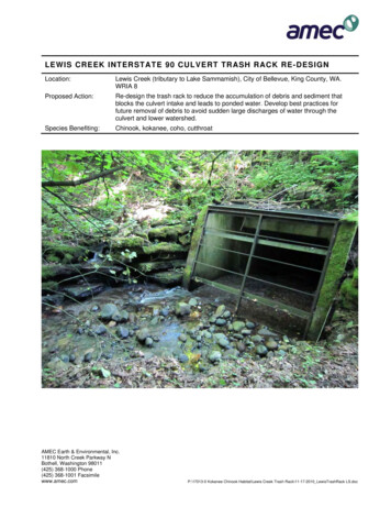
ACodes and Standards International Building Code (IBC – 2012)o Editorial Note: Model Building Codes (formerly ICBO, BOCAI,SBCCI) ASCE7 - xx (minimum design loads) RMI/ANSI MH16.1-2012 and MH26.2-2007 AISI (Spec. for Design of Cold -Formed Steel Structures) AISC (like AISI, except for structural steel shapes) AWS (welding) ACI 318 (concrete flooring) NFPA 5000 (building construction and safety) NFPA 13 (sprinkler systems ) FEMA 460 (Guidelines and seismicconsiderations for racking accessible to the public) NEHRP Recommended Provisions (Seismic)
ACodes and Standards
AHighlights:RMI/ANSI MH16.1-2012 & MH26.2-2007While a design guide, this American National Standard incorporatesprovisions that end users will find important in developingoperational protocols on many levels. Among the provisions are: A detailing of owner responsibilitiesFloor loadingPick-module designStair designHandrail and guardrail designDiscussion of product fall protection
DHighlights:RMI/ANSI MH16.1-2012 & MH26.2-2007Load Notices (Plaques) – Load Generalities
DHighlights:RMI/ANSI MH16.1-2012 & MH26.2-2007L o a d A p p lic a tio n a n d R a c k C o n f ig ur atio n D r aw in gsC o n f ig u r atio n Sp e c if ics
DHighlights:RMI/ANSI MH16.1-2012 & MH26.2-2007 Loads on racksLoad combinationsDetails of base-plates and shimmingPerformance of shelf -connection locking deviceShelf-beam deflection limitsSystem plumb and straight requirementsRequirements for cross -aisle tying and anchoringSeismic design requirementsAnd many more
Frequently Asked Questions
AWhat is a uniformly distributed load (UDL) vs. apoint load? Why is this important?The definition of UDL: Any static load which is evenly distributed over theentire surface on the rack deck. (Ref MH26.2). This means that theproduct being stored on the deck must cover the entire deck from side toside and front to back. General capacity ratings are based upon a UDLstored on the deck.Point Load - any static load that is concentrated to particular points on thedeck. (i.e. A container with four small feet (point load) versus a containerwith two runner bars running the entire length of the container(concentrated load).
DWhy should racks be anchored?The ANSI/RMI Specification requires that all rack columns should beanchored. This means that both the aisle column and the interior or rearcolumns must be anchored on all frames according to the instructions from themanufacturer and applies to all rack frames all the time. If there is a specificapplication where the racks can’t be anchored, the user should get permissionfrom the manufacturer’s engineer to waive the requirement. Anchors arerequired to resist many forces at the base of the columns and to maintain theposition of the rack column.
SThere are two holes in the footplate, why? Doesthat mean I need two anchors per footplate ?Not necessarily. Racks must always be anchored to the floor as shown on theLoad Application and Rack Configuration drawings. The RMI Specificationrequires at least one anchor per column. The rack manufacturer will oftenprovide extra holes in the base plate as alternate holes that can be used incase floor reinforcing interference is encountered when drilling the floor.
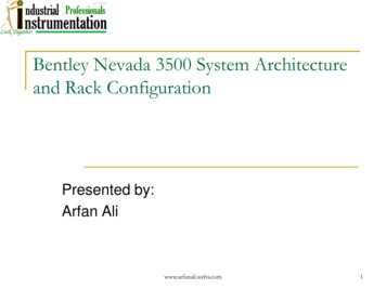
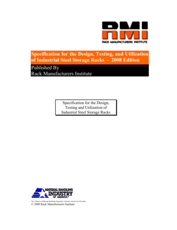
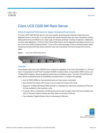
AHow far out of plumb can your racks be?The ANSI/RMI Specification permits the maximum out-of-plumb ratio for a loaded rack column to be 1/2” per10 feet of height. Columns whose out-of-plumb ratio exceeds this limit must be unloaded and re-plumbed. Anydamaged parts must be repaired or replaced. This ratio could be used for straightness also. In other words,the out-of-straightness limit between any two points on a column should not exceed 0.05” per foot of length(1/2” per 10 feet).An out-of-plumb or out-of-straight condition will reduce the capacity of a rack column. The reduction can besignificant. A rack that is out-of-plumb from top to bottom or a rack column that is not straight is likely tobecome further out-of-plumb or out-of-straight when it is loaded.The out-of-straight limit is given to prevent excessive “bows” or “dogleg” conditions that may exist in a rackcolumn. A column could be plumb from top to bottom but have an unacceptable bow at mid-height (see figure(a)), or a 20 ft. high column could be out 1” from top to bottom, which could be acceptable using a simple topto-bottom out-of-plumb measurement, but the entire out-of-plumb could be between the floor and the 5 ft. level(see figure (b)). This dogleg condition would be very harmful. This condition could be caused by fork truckimpact. The column could have a sine wave shape and be out of straight as shown in figure(c). A columncould also become bent and exceed this limit (see figure (d)). As re-written the specification now preventsthese situations from being acceptable if they exceed the 0.05" per foot out of straight limit.
AHow far out ofplumb can yourracks be?
DCan you tie racks to the building structure?It is generally not a good idea to tie racks to the wall because forces from thebuilding can be transferred to the racks and because forces from the rackscan be transferred to the building, although wall ties are sometimes used inlow seismic areas. If wall ties are used, there must be proper coordinationbetween the building engineer and the rack engineer to ensure that the tiesand any transmitted forces will not damage the rack or the building structures.The connection to the wall must be capable of transferring the required forces,and the connectors must be compatible with the wall material. The seismicanalysis of the rack and the building being tied together is extremely complex,and the connection is best avoided. If the height to depth ratio is such that asingle row needs extra stability, heavy-duty anchor patterns with larger baseplates or cross aisle tie configurations could be used rather than wall ties.
AWhat should you know about height -to-depthratios?The RMI defines the height-to-depth ratio for a single row of pallet rack to be the ratio of thedistance from the floor to the top beam level divided by the depth of the frame. Normalanchoring as is used for double rows is usually adequate for racks whose ratio is 6 to 1 or less.If the height-to-depth ratio exceeds 6 to 1, the anchors and the base plates should be designedto resist overturning. The ANSI/RMI Specification in section 8.1 provides for the anchorage toresist an overturning force of 350# applied at the topmost shelf level (to an empty rack). If theLRFD method of design is used, this force should be treated as a live load and multiplied by1.6.If the height-to-depth ratio exceeds 8 to 1, the racks should be stabilized using overhead ties. Ifanchoring is used for this extreme case, the design of the anchors must be certified by anengineer. All of these ratios and requirements are for a typical rack frame. If a set back leg orslope leg upright were to move the center of gravity from the frame’s midpoint, these ratio limitsdo not apply, and a rack engineer should approve the configuration. Slope or setback legsshould generally be avoided in single rows.
SAre there recommended clearances between palletloads?In the storage rack system planning, clearance around the loads is second only tothe size and shape of the loads. Too little clearance will result in damage to both theloads and the storage racks. In an effort to minimize the damage operators will slowdown the movement of the loads and greatly add to the operation cost of thewarehouse. Too much clearance will waste space and increase the costs ofconstruction, and, in some cases, the cost of the rack system.Automated Storage and Retrieval Systems have tighter operating tolerances and,therefore, may be able to function with tighter clearances. The user of theinstallation is responsible for assuring that these operating clearances are conveyedto the rack designer.
SAre there recommended clearancesbetween pallet loads?For normal load size, shape (and misshape) and weights asingle-selective pallet storage rack might be configured with4 inches (102 mm) clearance between the rack column andthe load and 5 inches (127 mm) between two adjacent loadson a beam. In a single deep storage configuration 6 inches(152 mm) lift-off clearance might be typical. For a doubledeep storage configuration more clearance would berequired. For push-back type pallet storage operations lessclearance may be used for pallets resting on moving carts,but care must be used to assure that the pallets can getunder all interior obstructions when accounting for the carttrack slope.
DHow much beam/shelf deflection is acceptable?At normal design working loads, beams are typically designed to accommodatevertical deflections that do not exceed 1/180 (or 0.55 percent) of the horizontalbeam length as measured with respect to the ends of the beams. Some usersmay specify a lesser-deflection requirement for visual appearance or cosmeticpurposes. Still other users with systems intended to use more preciseautomated storage and retrieval equipment may specify a lesser-deflectionrequirement. (See ANSI/RMI Specification section 5.3, Commentary section5.3).
SWhat does the load capacity on a Wire Deck reallymean? How should it be applied to the real world ?The load capacity assigned to a specific make and model of a wire deck is based on atesting protocol from MH26.2. This test is designed to evaluate the capacity (both strengthand deflection) of the wire decking when the deck is subjected to a uniformly distributed load.The test protocol is designed to have the entire load weight supported by the deckingcomponents. The test does not allow any of the weight to be supported by the shelf beamsor members other than the decking components.This test protocol is intended to allow the end user to compare the load carrying capacities ofdissimilar decking construction on an equal basis.The actual loading of a rack deck may or may not be uniformly distributed. Evaluation of thespecific loading and the deck’s ability to safely carry that load should be evaluated by anengineer who is familiar with the design of storage rack decks.
SWhy should you not walk on a wire deck?Wire decking is not designed to be walked or stood upon. Walking and/or standing on a wiredeck creates both dynamic (moving and varying) and concentrated loads. Wire decking isdesigned and assigned a load carrying capacity based on carrying uniformly distributed, staticloads. While there is a safety factor designed and built into wire decking, dynamic andconcentrated loading as a result of standing or walking on a wire deck is a use which fallsoutside its intended purpose. In addition, the surface of a wire mesh deck is flexible andirregular and the open areas within the mesh may cause a person to trip. Furthermore, whensubjected to lateral motion decks may slide upon the supporting rack beams or tip upward andbecome dislodged when loaded in a concentrated fashion on the outer extremities (beyond theoutermost support members).
DWhat is an acceptable repair?Upon any visible damage, the pertinent portions of the rack shall be immediatelyisolated by the user until the damaged portion is evaluated by a storage rackdesign professional. Before allowing the rack to be placed back into service thedesign professional must certify that the rack system and/or the repairedcomponents have been restored to at least their original design capacity.The detail used to make an acceptable repair should be designed or reviewedby a qualified design engineer and installed by people who are qualified tomake the repair. The rack repair should be reviewed for compliance to theANSI/RMI MH 16.1 Specification. A good repair will result in a structuralmember or connection that is at least as strong as the original.When welding is prescribed, the welders must be certified for the types ofwelded joint required.
AWhat should you know about used or repurposedracks?Racks that do not conform to the ANSI/RMI Specifications may not be as safe as racks thatconform to the specification. The Rack Manufacturer’s Specification is the only recognized U.S.specification for the design, testing
RMI/ANSI MH16.1-2012 & MH26.2-2007 While a design guide, this American National Standard incorporates provisions that end users will find important in developing operational protocols on many levels. Among the provisions are: A detailing of owner responsibilities Floor loading Pick-module design Stair design