Transcription
VIBRATION ANALYSIS OF PCBS AND ELECTRONIC COMPONENTSA THESIS SUBMITTED TOTHE GRADUATE SCHOOL OF NATURAL AND APPLIED SCIENCESOFMIDDLE EAST TECHNICAL UNIVERSITYBYBANU AYTEKİNIN PARTIAL FULFILLMENT OF THE REQUIREMENTSFORTHE DEGREE OF MASTER OF SCIENCEINMECHANICAL ENGINEERINGAPRIL 2008
Approval of the thesis:VIBRATION ANALYSIS OF PCBS AND ELECTRONIC COMPONENTSsubmitted by BANU AYTEKİN in partial fulfillment of requirements for the degreeof Master of Science in Mechanical Engineering Department, Middle EastTechnical University by,Prof. Dr. Canan ÖzgenDean, Graduate School of Natural and Applied SciencesProf. Dr. S. Kemal İderHead of Department, Mechanical EngineeringProf. Dr. H. Nevzat ÖzgüvenSupervisor, Mechanical Engineering Dept., METUExamining Committee MembersProf. Dr. Y. Samim ÜnlüsoyMechanical Engineering Dept., METUProf. Dr. H. Nevzat ÖzgüvenMechanical Engineering Dept., METUProf. Dr. Mehmet ÇalışkanMechanical Engineering Dept., METUAsst. Prof. Dr. Yiğit YazıcıoğluMechanical Engineering Dept., METUDr. Mutlu D. CömertTÜBİTAK-SAGEDate:
I hereby declare that all information in this document has been obtained andpresented in accordance with academic rules and ethical conduct. I also declarethat, as required by these rules and conduct, I have fully cited and referencedall material and results that are not original to this work.Name, Last name: Banu AytekinSignature:iii
ABSTRACTVIBRATION ANALYSIS OF PCBS AND ELECTRONIC COMPONENTSAytekin, BanuM.S., Department of Mechanical EngineeringSupervisor: Prof. Dr. H. Nevzat ÖzgüvenApril 2008, 118 PagesIn this thesis, vibration analyses of electronic assemblies that consist of an electronicbox, printed circuit board and electronic components are presented. A detailedvibration analysis of a real electronic assembly is performed by finite elementmethods and vibration tests. Effects of component addition and component modelingare investigated by finite element analysis in detail. Results are compared in order toidentify the most efficient, reliable and suitable method depending on the type ofproblem. Experimental results for the vibration of an electronic box, PCB andcomponents are presented and discussed. Furthermore, an analytical model thatrepresents a printed circuit board and electronic component is suggested for fixedand simply supported boundary conditions of the PCB. Different types of electroniccomponents are modeled analytically to observe different dynamic characteristics.The validity of the analytical model is computationally checked by comparing resultswith those of finite element solution.Keywords: Electronic Assembly, Printed Circuit Board, Electronic System Vibrationiv
ÖZELEKTRONİK KARTLARIN VE PARÇALARIN TİTREŞİM ANALİZİAytekin, BanuYüksek Lisans, Makina Mühendisliği BölümüTez Yöneticisi : Prof. Dr. H. Nevzat ÖZGÜVENNisan 2008, 118 SayfaBu çalışmada; kart kutusu, elektronik kart ve elektronik parçaların oluşturduğu birelektronik bütünün titreşim analizleri gerçekleştirilmiştir. Gerçek bir sistemdekullanılan elektronik bütünün sonlu eleman yöntemi ve titreşim testleri ile yapılanayrıntılı titreşim analizleri sunulmuştur. Kart üzerine elektronik parça eklenmesininve bu parçaların modellenmesinin titreşim karakteristiğine etkileri sonlu elemanlaranalizleri ile detaylı şekilde incelenmiştir. Elde edilen sonuçlar en etkin, güvenilir veuygun çözüm yöntemini problem tiplerine göre belirleyebilmek artveelektronikparçalariçingerçekleştirilen titreşim testleri sunulmuş ve sonuçlar değerlendirilmiştir. Buçalışmaların sonrasında, belirli sınır koşullarına sahip elektronik kartı ve üzerineyerleştirilmiş elektronik parçayı temsil eden analitik bir yöntem sunulmuştur.Değişik özelliklerdeki elektronik parçalar modellenerek dinamik davranışları eldeedilmiştir. Analitik modelin geçerliliği, sonlu eleman çözümlemelerinin sonuçlarıkullanılarak doğrulanmıştır.Anahtar Kelimeler: Elektronik Bütünler, Elektronik Kartlar, Elektronik SistemlerinTitreşimiv
To My Gorgeous Mothervi
ACKNOWLEDGMENTSThe author wishes to express her deepest gratitude to her supervisor Prof. Dr. ce,advice,criticism,encouragements and insight throughout the research.The author would like to express her appreciation to Mümtaz Afşın Esi for hisguidance and unlimited help during the research.The author would like to thank to her colleagues in TUBITAK-SAGE, especially toMehmet Sinan Hasanoğlu and Ethem Bozkurt for their support.The author would also like to express her gratefulness to her friends Çiğdem, Filiz,Nevra, Özge, Serdar and İlke for their support throughout the research.The author would like to express her gratitude to Tolga Tekşen for his faith in me,patience, consideration and great support during the research.The author would like to thank her family, especially her mother Naciye Aytekin forher support and patience throughout the research.The facilities and support provided by TÜBİTAK-SAGE are kindly appreciated.Domestic Master of Science Scholarship provided for the author by the Scientificand Technological Research Council of Turkey (TUBİTAK) is gratefullyacknowledged.vii
TABLE OF CONTENTSABSTRACT. ivÖZ . vACKNOWLEDGMENTS .viiTABLE OF CONTENTS.viiiLIST OF TABLES . xiLIST OF FIGURES .xiiiLIST OF SYMBOLS AND ABBREVIATIONS . xviCHAPTERS1. INTRODUCTION . 11.1 Printed Circuit Board . 11.1.1 PCB Usage in Industry. 11.1.2 Printed Circuit Board Materials . 21.1.3 Printed Circuit Board Assembly Elements . 41.1.4 Mounting of Printed Circuit Boards . 41.2 Electronic Component Mounting. 81.3 Failure Modes of Electronic Devices. 91.4 Vibration of Electronic Assemblies . 101.4.1 Failure of Electronic Assemblies due to Vibration. 101.5 Objective of the Study . 121.6 Scope of Thesis . 132. LITERATURE REVIEW . 153. FINITE ELEMENT VIBRATION ANALYSES OF ELECTRONIC BOXAND PCB . 233.1 Finite Element Vibration Analysis of Electronic Box . 243.1.1 Finite Element Vibration Analysis of Base of Electronic Box . 263.1.2 Finite Element Vibration Analysis of Electronic Box with FrontCover. 27viii
3.1.3 Finite Element Vibration Analysis of Electronic Box with Frontand Top Covers . 293.2 Finite Element Vibration Analysis of Printed Circuit Board. 333.2.1 Analysis of the Connector Mounted Edges . 353.2.2 Printed Circuit Board with Components Added . 433.2.3 Analysis of PCB Mounted in Electronic Box . 483.3 Finite Element Vibration Analysis of Electronic Assembly. 504. EXPERIMENTAL ANALYSIS. 554.1 Experimental Setup. 554.2 Experiment 1. 614.3 Experiment 2. 624.4 Experiment 3. 634.5 Experiment 4. 654.6 Experiment 5. 664.7 Experiment 6. 684.8 Comparison of Finite Element and Experimental Results. 705. ANALYTICAL MODEL . 755.1 Electronic Box Vibration as a Rigid Body . 755.2 Printed Circuit Board Vibration. 765.2.1 The Natural Frequency of a Plate . 765.2.2 Sandwich Plates . 775.2.3 PCB Geometry and Material Properties. 785.2.4 Discrete Modeling of PCB. 815.2.4.1 PCB with Fixed Edges . 815.2.4.2 PCB with Simply Supported Edges . 835.3 Discrete Modeling of Electronic Component . 885.3.1 Case Study I-An Oscillator . 895.3.2 Case Study II-An Integrated Circuit . 945.4 Random Vibration Analysis of the Analytical Model . 985.4.1 Transmission of Random Vibration. 99ix
5.5 Validation of the Model . 1036. SUMMARY AND CONCLUSIONS. 1086.1 Finite Element Modeling . 1086.2 Experimental Study. 1096.3 Analytical Model . 1106.4 Design Guidelines. 1126.5 Suggestions for Future Research . 113REFERENCES. 114x
LIST OF TABLESTable 1. PCB laminate materials and common applications [4]. 3Table 2. Electronic box dimensions . 25Table 3. First two natural frequencies of the base . 26Table 4. First two natural frequencies of the box with front cover. 28Table 5. Natural frequencies of the box with its covers. 30Table 6. PCB dimensions. 34Table 7. PCB dimensions-without connectors . 39Table 8. Natural frequencies of the actual and assumed models . 40Table 9. First mode comparison with real and assumed configurations . 41Table 10. Second mode comparison with real and assumed configurations. 42Table 11. Component masses. 45Table 12. Natural frequencies and mode shapes of component added PCB. 46Table 13. Natural frequencies of the PCB and box assembly. 49Table 14. First natural frequencies of PCB configurations. 51Table 15. Natural frequencies and mode shapes of electronic assembly with differentcomponent modeling approaches. 52Table 16. Transmissibility of the fixture at natural frequencies . 58Table 17. Summary of sine sweep testing conditions . 58Table 18. Summary of sine sweep testing configurations. 59Table 19. Transmissibility of the top cover at natural frequencies - Experiment 4 . 66Table 20. Transmissibility of the largest component -Experiment 5 . 67Table 21. Transmissibility of component and PCB at natural frequenciesExperiment 6 . 70Table 22. Natural frequencies and mode shapes of the test item with differentcomponent modeling approaches. 72Table 23. PCB dimensions. 80Table 24. Material properties of PCB laminas. 80xi
Table 25. First natural frequency and vibration parameter of PCB with fixed edges 83Table 26. The equivalent stiffness, equivalent mass and first natural frequency ofPCB with simply supported edges . 87Table 27. Analytical and finite element solution comparison of PCB naturalfrequencies . 88Table 28. Oscillator properties. 90Table 29. Oscillator properties. 90Table 30. Natural frequency values for integrated circuit. 92Table 31. Natural frequency values for oscillator and PCB system . 93Table 32. First natural frequency values for integrated circuit and PCB systemobtained by lumped mass model . 93Table 33. Lead wire properties. 95Table 34. Spring constant for IC’s lead wire . 96Table 35. Natural frequency values for integrated circuit. 97Table 36. Natural frequency result of analytical model. 102Table 37. Natural frequency comparison between analytical and finite elementsolution. 106Table 38. Acceleration PSD comparison between analytical and finite elementsolution. 106xii
LIST OF FIGURESFigure 1. An example of a a) PCB [2] b) PCB assembly [3] . 1Figure 2. An example of an electronic box-1 [5] . 5Figure 3. An example of an electronic box-2 [6] . 5Figure 4. Card-lok retainer [7] . 5Figure 5. PCB mounting elements [8] . 6Figure 6. PCB mounting elements [9] . 6Figure 7. PCB mounting elements [10] . 6Figure 8. PCB mounting elements [11] . 7Figure 9. An example of a backplane [12]. 7Figure 10. Through-hole mounting . 8Figure 11. Types of surface mounting . 8Figure 12. Failure mode distribution [13] . 9Figure 13. Ruptured lead wires due to fatigue [15] . 11Figure 14. Solder joint fatigue failure [16] . 11Figure 15. Solder joint crack initiation [16]. 12Figure 16. Dynamic model of vibration - isolated electronic box containing PCB[20] . 17Figure 17. Model of CCGA on PCB [38] . 21Figure 18. Electronic box components and assembly. 24Figure 19. First mode shape of the base of the electronic box. 27Figure 20. First mode shape of the base with front cover. 28Figure 21. a) Second mode shape of the base with front cover b) Same mode withfront cover hidden . 29Figure 22. a) First mode shape b) Second mode shape of the base with front and topcovers . 31Figure 23. a) Third mode shape b) Fourth mode shape of the base with front and topcovers . 31Figure 24. Fifth mode shape of the base with front and top covers . 32xiii
Figure 25. PCB connection points-top view . 32Figure 26. PCB geometry. 33Figure 27. PCB layers . 34Figure 28. Connector. 35Figure 29. PCB Connection Points . 36Figure 30. Displacement of PCB through path-1. 37Figure 31. Displacement of PCB through path-2. 37Figure 32. Displacement of PCB through path-3. 38Figure 33. Assumed configurations of PCB without connectors. 39Figure 34. Schematic view of components on the PCB. 45Figure 35. Second mode shape of the lumped model at 1905 Hz. 47Figure 36. Fourth mode shape of the assembly-contour plot in z direction (front andtop cover hidden). 50Figure 37. a) Second (1631 Hz) and b) third (1748 Hz) mode shapes of the PCB withlumped components (top cover hidden). 53Figure 38. Shakers and slip table [41]. 56Figure 39. LMS SCADAS III data acquisition hardware [41] . 56Figure 40. Transmissibility of the fixture . 57Figure 41. Transmissibility of the base of the box (Experiment 1) . 61Figure 42.Transmissibility of the box (Experiment 2). 63Figure 43.Transmissibility of base of the box (Experiment 3) . 64Figure 44. Transmissibility of the top cover (Experiment 4). 65Figure 45. Transmissibility of the largest component (Experiment 5) . 67Figure 46. Transmissibility of the PCB and the largest component (Experiment 6) . 69Figure 47. a) Second (1621 Hz) and b) third (1732 Hz) mode shapes of the PCB withlumped components in electronic box. 73Figure 48. Sandwich plate [42] . 77Figure 49. PCB layers . 79Figure 50. PCB geometry. 79Figure 51. Point Load on the PCB with Fixed Edges . 82xiv
Figure 52. Point Load on the PCB with Simply Supported Edges . 84Figure 53. Oscillator front view . 89Figure 54. Three dof model of oscillator . 91Figure 55. Discrete model of PCB and oscillator . 92Figure 56. Integrated Circuit Top View [28] . 94Figure 57. Lead wire geometry of the integrated circuit [44] . 95Figure 58. Three dof model of integrated circuit . 96Figure 59. Side view of lead wire deflection for large components . 98Figure 60. Random vibration input . 99Figure 61. PCB and component 2 dof model. 100Figure 62. Random vibration response of oscillator bonded over fixed PCB . 102Figure 63. Random vibration response of oscillator bonded over simply supportedPCB . 103Figure 64. Finite element model of oscillator bonded over PCB. 104Figure 65. Oscillator response comparison of analytical model and finite elementsolution for fixed PCB . 104Figure 66. Oscillator response comparison of analytical model and finite elementsolution for simply supported PCB . 105xv
LIST OF SYMBOLS AND ABBREVIATIONSc: Damping constantCEM-1: Composite Epoxy Material 1CEM-3: Composite Epoxy Material 3[C]: Damping matrixCCGA: Ceramic Column Grid Arraydof: Degree of freedomD: Flexural RigidityE: Young’s Modulusf: Frequency in HzF: Fixed endFR-2: Flame Resistant 2FR-3: Flame Resistant 3FR-4: Flame Retardant 4g: gramsGI: Glass filled polyimideGT: Glass filled TeflonH(ω): Frequency response functionI: Area moment of inertiaIPC: Interconnecting and Packaging Electronic Circuitsk: Spring constant[K]: Stiffness matrixxvi
m: Mass[M]: Mass matrixPCB: Printed Circuit BoardPSD: Power Spectral DensityPWB: Printed Wiring BoardSS: Simply supported edgeS(ω): Spectral densityT: Kinetic energyw: Deflection of a plateν: Poisson’s ratioγ: Mass per unit areaμ: Densityω: Frequency in radian per secondδ: Deflection of a beamε: Strainσ: Stressxvii
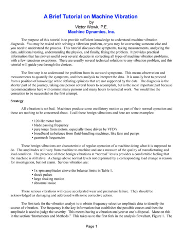
CHAPTER 1Equation Chapter 1 Section 1INTRODUCTION1.1Printed Circuit BoardPrinted circuit board (PCB), which is also referred as printed wiring board (PWB), isused primarily to create a connection between components, such as resistors,integrated circuits, and connectors [1]. It becomes an electrical circuit whencomponents are attached and soldered to it, which then is called printed circuit boardassembly (Figure 1).a)b)Figure 1. An example of a a) PCB [2] b) PCB assembly [3]1.1.1PCB Usage in IndustrySerious use of printed circuit assemblies began shortly before the end of World WarII. One of the first applications for these assemblies was in a radio set. Another type1
of circuit board was designed for use in proximity fuzes. By the end of the war, thesewere being produced successfully in very large quantities [4].In today’s world, all high technology devices contain printed circuit boards. Theirsizes, shapes, properties and endurances vary depending on where they are utilized.Standards developed by the Institute for Interconnecting and Packaging ElectronicCircuits (IPC) identify the following three classes of electronic products in whichprinted circuit board assemblies are used [4]: Class 1: General products, including consumer items, computers andperipherals, and some military systems. Class 2: Dedicated service products, including communication equipment,business machinery, industrial controls, instruments, and military systems,where extended life and reliable service is needed. Class 3: High-reliability products, including equipment and systems wherecontinuous performance or performance on demand is essential.1.1.2Printed Circuit Board MaterialsA printed circuit board is a composite structure. Many types of copper-clad materialsare available, but the ones used most commonly for PCBs are FR-4, FR-2, FR-3,CEM-1, CEM-3, GI and GT. Table 1 contains basic features of various laminatematerials [4]:2
Table 1. PCB laminate materials and common applications [4]TypeFR-4ConstructionApplicationsMultiple layers of wovenWidely used inglass cloth impregnatedcomputers, industrialwith epoxy resin; firecontrols,retardanttelecommunications andmilitary/space systemsFR-3Multiple layers of paperFound in consumerimpregnated with flame-products such asretardant epoxy resincomputers, TVs, andaudio equipmentFR-2CEM-1CEM-3GIGTMultiple layers of paperMainly used in consumerimpregnated with flame-electronics such as games,retardant phenolic resinradios and calculatorsGlass cloth impregnatedUsed extensively inwith epoxy on outerindustrial electronics,surfaces of paper coresmoke detectors and forimpregnated with epoxyautomotive devicesGlass cloth impregnatedUsed in appliances,with epoxy on outerautomobiles andsurfaces of fiberglass corecommercialimpregnated with epoxycommunication equipmentMultiple layers of wovenUsed in products exposedglass cloth impregnatedto high-temperaturewith polyimide resinenvironmentsGlass fabric base withApplied where lowTeflon resindielectric constant isneeded for high-frequencycircuits.3
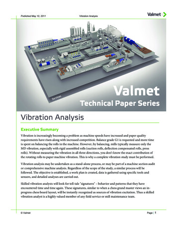
1.1.3Printed Circuit Board Assembly ElementsPrinted circuit board assemblies are commonly composed of a similar set of basicelements. These are [4] Electronic components that perform the intended circuit functions desinterconnections between them One or more connectors that are used as an electrical interface between theprinted circuit board assembly and the rest of the system Mechanical parts for mounting parts and hardware to the board, attachingPCB to the system, providing thermal paths and supporting and stiffening theassembly1.1.4Mounting of Printed Circuit BoardsPCBs are very sensitive to environmental conditions. Depending on the device typein which a PCB is utilized, different requirements come into existence such asmechanical integrity of a system, durability against thermal loading and preventionof electromagnetic interference (EMI). In order to meet such requirements PCBs aremounted onto frames or into box-like structures.Electronic boxes are usually composed of one or more covers and a body whereprinted circuit boards are mounted. Examples of an electronic box are given inFigure 2-3.4
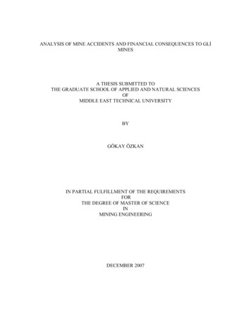
Figure 2. An example of an electronic box-1 [5]Figure 3. An example of an electronic box-2 [6]PCBs are usually connected to an electronic box by screws or card-lok retainers.Screws occupy less space on a PCB compared to card-lok retainers. However, morerigid connections are often provided by card-lok retainers especially for larger PCBs.An example of a card-lok retainer is given in Figure 4.Figure 4. Card-lok retainer [7]5
There are also many products to increase rigidity of a PCB mounted with screws.These additional mechanical parts are designed for absorbing mechanical loadsapplied to PCB connection points. Some examples of PCB mounting elements aregiven in Figures 5-8.Figure 5. PCB mounting elements [8]Figure 6. PCB mounting elements [9]Figure 7. PCB mounting elements [10]6
Figure 8. PCB mounting elements [11]Another important issue about printed
Approval of the thesis: VIBRATION ANALYSIS OF PCBS AND ELECTRONIC COMPONENTS submitted by BANU AYTEKİN in partial fulfillment of requirements for the degree of Master of Science in Mechanical Engineering Department, Middle East Technical University by, Prof. Dr. Canan Özgen Dean, Graduate Schoo