Transcription
Application NotesVibration Diagnostics for Industrial Electric Motor DrivesThe induction motor is the most widely employed industrial electric-drive. Identifying the vibration problems that canoccur in induction-motor drives have an added complexity due to the rotating magnetic-fields in the machine. Abasic understanding of the principles involved, together with a simple trouble-shooting guide and the right analysisinstrumentation, should be invaluable to the maintenance engineer.
Vibration Diagnostics for Industrial Electric Motor Drivesby Glenn H. Bate, B.Sc, M.Sc, Dip. UCL. Bruel&KjcerIntroductionBy far the most widely employed electric motor in industrial drives, is theinduction motor and this applicationnote applies to this type of electricmotor. Engineers should be able to relate some of the principles to synchronous motors or generators etc., but, forbrevity, only the induction motor isspecifically discussed. The effects ofelectronic variable speed drives* arenot discussed either; operation on amains frequency supply is assumed.5'Magnetic' or 'Mechanical ?The vibration problems relating to theinduction motor are a combination oftwo groups which can be called 'mechanicaV and 'magnetic', according tohow they arise (this is made clear inthe following sections).To help determine which of the twogroups of vibration are present, themaintenance engineer can listen forbeats. A beat is identified as an oscillatory amplitude of vibration, due toclosely spaced frequency componentsalternately reinforcing then cancellingeach other, as their relative phase varies. The absence of beats may indicatethere is only a 'mechanical' problem.Their presence can indicate a 'mechanical' problem and 'magnetic' onecombined. For example, such compo, r,i j, ,nents in a z-poieinduction motor,1'tude modulation of a single frequency7component, due to a 'magnetic problem alone. How amplitude modulationcomponents and beat frequency components can appear in the inductionmotor is explained later.More can be discovered about theproblem by disconnecting the electricsupply (a 'power trip test'). This willdistinguish the 'mechanical' and the'magnetic' components of vibration,since 'magnetic' components will disappear immediatelyafter electricalpower is removed. The effect of thepower trip test should be observed bystudying the changing amplitude ofthe vibration on a spectrum analyzer.Spectrum AnalysisFurther analysis of the vibration spectra is required to separate out specificfaults, and therefore to determine theappropriate rectification action. Thiscan be done using a high resolutionspectrum analyzer: typically an F F T(Fast Fourier Transform) analyzerwith an increased resolution 'zoom' facility. The resolution is needed to pickout the narrow-band and sidebandsignatures of all the vibration problems occurring with induction motordrives. This application note describeswhat these signatures are and how ori, /» j ,i,i-iwhere to find them using the analyzer.J COUld OCCUr a t c l o s e l y S p a c e d f r e q u e n -cies of twice rotational speed andtwice the supply frequency respectiveily.JNotice that an oscillatory amplitudeof vibration also occurs with ampli2A Complex ProblemThis short application note concen, i,i , jiimitrates on the magneticproblems,thet ftreatment of the 'mechanical' vibration problems relating to the rotatingshaft is brief, concentrating on the resuits rather than the causes. The 'resuits' are often seen in associationwith some of the 'magnetic' vibrationproblems, because 'mechanical' problems such as unbalance, misalignmentand looseness can affect the inductionmotor magnetic circuit, by causingvariations in the air-gap. The problemis further complicated since industrialelectric drives are often mounted onrails or box structures as commonbases to the driven equipment. Thismeans that measured spectra can contain components due to gearing, bearings etc., transmitted via the structure. Also any spectrum componentwill vary depending on the mobility ofthe path from the various vibrationsources to each measurement point.The answer to this complex problemis to identify the specific vibration signatures, and while this applicationnote provides information on only induction motor vibration, Briiel&Kjaerare publishing a series of applicationnotes relating to vibrations in shafts,gears, bearings etc.* Electronic variable speed drives such as d.c.link invertors or cyclo-convertors achieve, , t,/,u . rspeed control through synthesis oi a varyingfrequency supply by electronic switching. Dueto this, the current supplied has a degree ofharmonic distortion, depending on the sophistication of the electronics, filters etc. The dis,tortion,. oi,,,the current, waveform'„ .reflects in iUthevibration spectrum, this relationship is madeclear in this application note.
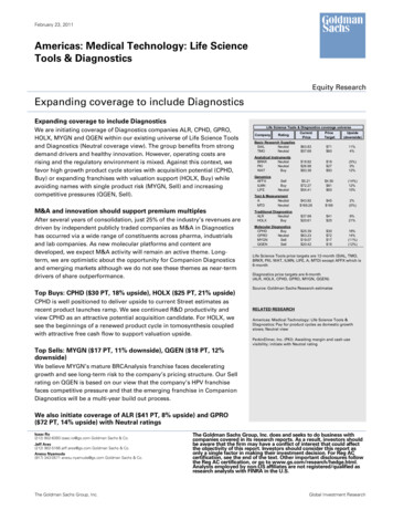
'Magnetic'VibrationInduction MotorsinPrinciplesThe induction machine is shown insimplified form in Fig. 1. Current isproduced in the rotor conductors,which is proportional to the differencein speed between the rotating field,produced by the current in the 3phase stator windings, and the rotoritself. This current produces a rotorfield which interacts with the statorfield to generate force on the rotor.The field in the rotor rotates in syn chronism with the rotating field in thestator; both advance 2-pole pitches relative to the stator, for each cycle ofline frequency, i.e. at synchronousspeed. The rotor of the induction mo tor does not rotate at synchronousLOUSspeed, but instead slips backwardsthrough the rotating field. The rate ofslip is the difference between synchro nous speed and rotor speed.Since synchronous speed dependson the line frequency and the numberof poles in the machine, it is conve nient to use the per-unit slip as de fined in Fig. 1., and define slip frequency as per-unit slip x line frequen cy. This definition of slip frequencyapplies to all motors regardless ofthe number of poles. The slip fre quency is the actual frequency of thecurrent in the rotor conductors, andthe rotating fields advance relative tothe rotor by 2-pole pitches for eachcycle of slip frequency.Motor torque is produced where bal anced forces exist on either side of therotor. If the forces of attraction are notbalanced, then vibration results. Thiscan be related to current or air-gapvariations in induction motors.Current Variations Due to Rotor orStator FaultsConsider a simple coil rotatingthrough a magnetic field as shown inFig. 2. It is well known that the forceon a current carrying conductor in amagnetic field can be obtained fromthe vector cross product of the currentvector and the flux density vector.This can of course be applied to thecoil in Fig. 2, but here another moregeneral expression of the force on thecoil is given, relating to the total flux #linking the coil. The relationship givenin Fig. 2. shows that the force on thecoil, in any arbitrary direction 'x', isdirectly proportional to the current inthe coil and the rate of change of themagnetic flux in the direction of theforce (and not the flux itself). TheFig. 1. The induction motor stator, rotor & air-gapFig, 2, The force on a current carrying coil moving in a magnetic fieldterm NI is called the magnetomotiveforce (MMF) and the rotating field inthe induction motor can be defined asan MMF wave in the conductors, giving rise to a flux wave in the air-gap.By likening conductors on either sideof the rotor to the two sides of the coil,a number of broken bars can be considered as introducing an unbalance ofMMF and thus force between the twosides of the rotor. This force unbalancerotates with the rotor. The equationgiven in Fig. 2 however, reveals thatthe force unbalance is obtained from amultiplication of the MMF unbalanceand the rate of change of magneticflux in the direction of the force. If theproblem can be simplified by neglect-3
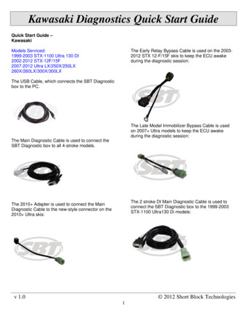
ing other than fundamental components of the MMF wave, then the unbalance force can be described by theproduct of two alternating terms offundamental frequency, but which arenot necessarily in phase, of the form:k sin sa?t sin(sa t 6)or,(/e/2)(cos - cos(2scvt 0))where,to the line frequencys the per-unit slipk an amplitude value0 a phase anglei.e. the vibration has a constant partand a 2 x slip frequency alternatingpart. Transforming this to a stationary reference frame requires a frequency multiplication of 1 x RPM. Astationary transducer, positioned forinstance on the rotor shaft bearinghousing, will therefore measure a vibration with components of 1 x RPMand 2 x slip frequency sidebandsabout a centre frequency of 1 x RPM.By similar reasoning, if the currentdiscontinuity is due to a fault in thestator windings, e.g. shorted statorturns, then the resulting force unbalance does not rotate, and is of theform:(fe/2)(cos# - cos(2o 6))i.e. The vibration has a constant component and a component at 2 x linefrequency.A i r - g a p V a r i a t i o n s D u e t o EccentricityNow consider the relationship given inFig. 2 with regard to air-gap variations. The flux in the air-gap is generated by the total MMF of the magnetic circuit, such that the flux:same MMF will result in greater flux.T h e travelling sinusoidal flux wavewill thus experience a greater rate ofchange as it enters this region of theair-gap. The effects of a varying airgap may thus be similar to the effectsof current variations. The same relationship for the unbalance force resuits, where only fundamental frequency components of MMF are considered. Static eccentricity refers to aneccentricity which does not travel (e.g.due to bearing wear or misshapen stator), this will produce a vibration forcewith components at d.c. and 2 x linefrequency. Dynamic eccentricity travels with the rotor (e.g. due to rotorbow), this will produce a vibrationforce a t 1 x RPM a n d 2 x slip frequency sidebands on 1 x RPM. Indeed these statements are justified bypractical results, but consideration ofthe variation of the reluctance as aperiodic function (of space, in the caseof static eccentricity, and of time andspace, in the case of dynamic eccentricity), suggests different componentsto look for as the best indication ofeccentricity. This is dealt with in thesection "Advanced Analysis & OtherTechniques" later in this applicationnote.the inertia constant of the rotor shaft,some speed variation may result. Thespeed variation will be larger for lowinertias, and this can therefore cause afrequency modulation of the vibrationcomponents whose frequency is referenced to rotor speed. For high inertiasthe speed variation and therefore thedegree of frequency modulation willbe less.Where sidebands are generatedthen, the general case is somewherebetween pure amplitude modulationand frequency modulation. The spacing between each sideband componentis still the modulating frequency, however, in the case of frequency modulation the number of sidebands can bemuch greater than two, depending onthe modulation index, i.e. the ratio ofthe peak frequency (or speed) deviation to the modulating frequency (orthe frequency of the torque variations). See Fig. 3.Slot F r e q u e n c i e sThe slots carrying the conductors inthe induction motor, also generate avibration force as they create unbalanced magnetic forces of attraction,resulting from an effective variation ofreluctance in the magnetic circuit as afunction of the rate of stator and rotorslot passing. The components will bepresent in a 'healthy' motor of course,since the slots are part of the design,and these will always tend to concentrate the magnetic field in the slotteeth rather than the slot channel, dueto higher magnetic permeability in thematerial in the teeth than in the conductors in t h e channels. T h e vibrations occur at the frequencies given bythe equation in Fig. 4, which represents the principal harmonic contentof the resulting force function.'Rotating' or 'Stationary'?The 'magnetic' problems discussed sofar, can also be classified as either a'rotating' or a 'stationary' problem, according to the vibration produced. Apresentation of this with some typicalcauses is given in Table 1.Frequency Modulation D u e toSpeed VariationsT h e discontinuities in the magneticforces of attraction giving rise to vibration as discussed, also cause variations in motor torque. Depending on# F IRwhere,Fm the total MMFRm the total magnetic reluc tance in the circuitAny eccentricity in the air-gap resultsin a variation of the magnetic reluc tance, which depends on the radial' rX . «. . ,air-gap length. I his effect is particu,i4. J *K.\ 1lType ofuDmkmProblemProblemI I71 ZSymptomatic Frequency„«\#;K,„*i of VibrationAir-gap VariationsVariationsCurrent Variations2 x line frequencyZJLStaticeccentricity,Static eccentricity,weaknessof statorweaknesssupport of statorStatorStatorfaultsIthen the reluctance decreases and theTable 1. 'Rotating' and 'stationary'4StationaryRotatinaRotatingTunirai r a n TypicalCauselypicaiuause1of Vibrationlarly apparent in induction motors, asthese require a very narrow air-gap,compared to synchronous motors ordirect current machines. Thereforesmall defects can result in relativelylarger reluctance variations in induetion motorsIf the air-gap narrows for instance,Stationary12 x line frequencysupportDynamicDynamic11 XxRRPMP M w withi t h 2 2x x slip frequen- tricityslipfrequen- tricityCcysidebandsLooserotorY sidebandsLoose rotorI„Iecceneccenbar(s)bar(s)'magnetic' vibration in inductionwindingwindingfaultsBrokencrackedBroken oror crackedrotorbar(s),orrotor bar(s), orshortedrotorlamishorted rotor laminationsITYi iOQQt Of}TmRQvnmnmotors
Fig. 3. Amplitude spectra of sidebands for frequency modulation with various values of modulation index ftThe 'Mechanical' VibrationProblems of the RotatingShaftA brief description of the 'mechanical'vibration problems resulting fromfaults occurring on the rotating shaftis appropriate, since these problemsare often interdependent with 'mag netic' vibrations as described alr
Further analysis of the vibration spec- sources to each measurement point. To help determine which of the two tra is required to separate out specific The answer to this complex problem groups of vibration are present, the faults, and therefore to determine the is to identify the specific vibration sig- maintenance engineer can listen for appropriate rectification action. This natures, and .