Transcription
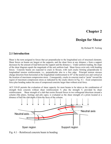
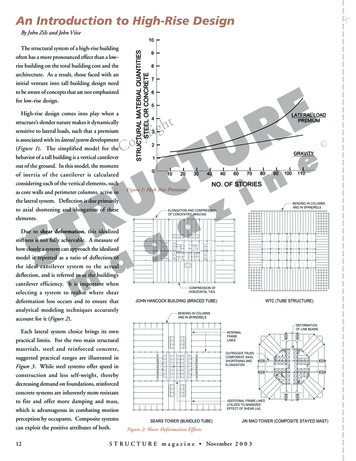
Keynote AddressRock Dumps 2008 — A. Fourie (ed) 2008 Australian Centre for Geomechanics, Perth, ISBN 02 1 Barton/Shear Strength of Rockfill, Interfaces and Rock Joints, and their Pointsof Contact in Rock Dump DesignN.R. Barton Nick Barton and Associates, NorwayAbstractThe peak shear strength of rock joints obtained from direct shear tests, and the peak shear strength ofrockfill, as interpreted from large-scale triaxial tests, have common non-linear strength envelopes. Anextremely low stress index test for rock joints, the tilt test, with an apparent normal stress as low as0.001 MPa when sliding occurs, can also be performed to characterise rockfill. However for rockfill or rockdumps, larger samples with relevant particle sizes are desirable. Some full-scale tests at a dam site in Italy,using a 2x2x5 m tilt-shear test, were able to sample the as-compacted-as-built rockfill, with no need forusing parallel (model) grading curves with reduced-sized particles. Interfaces between the rockfill or rockdump and eventual rock foundations, can be handled with similar shear strength estimation methods. In eachcase, a low-stress index test result is extrapolated to full scale and to engineering stress level by related nonlinear strength laws. It is possible to estimate each through inexpensive characterisation. The non-linear,stress-dependent friction angles suggest that large rock dumps with constant slope angle will have stronglyreducing factors of safety from top to bottom and from outside to inside.1IntroductionThe real contact stress levels are believed to be close to compressive failure where rock joint asperities androckfill stones are in contact (e.g. Figure 1 for the case of rock joints). Therefore it is perhaps possible to usea common form of constitutive equation for extrapolating the strength measured at very low (index test)normal stress levels, to stress levels of engineering interest, as inside a large rockfill dam, inside a rock dumpor under a rock slope formed of jointed rock.Figure 1When peak shear strength is approached (joints and rockfill), the actual rock-to-rockcontact stress levels are extremely high, due to small contact areasIt is believed that the real ratios of σcn /JCS (contact normal stress/joint wall compressive strength, in the caseof rock joints) and σcn /S (contact normal stress/particle strength,in the case of rockfill) are equal to the ratioA0 / A1 representing the ratio of true contact area/assumed contact area. The terms JCS and S represent thejoint compressive strength and the particle strength, respectively. In other words, contact area is a rockstrength or particle strength regulated phenomenon at peak strength.Tilt tests are performed on a regular basis to characterise the roughness of rock joints. A schematic exampleof tilt testing for rock joints is shown in Figure 2, while a suggested method for testing rockfill at full scale(without needing parallel grading curves) is shown in Figure 3, from Barton and Kjærnsli (1981).Rock Dumps 2008, Perth, Australia3
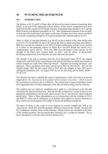
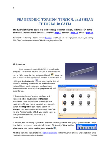
Shear Strength of Rockfill, Interfaces and Rock Joints, and their Pointsof Contact in Rock Dump DesignFigure 2N.R. BartonTilt test (or self-weight gravity shear test) for characterising rock joints. Note measurementof basic friction angle on unweathered, smooth (but not polished) pieces of coreThe equation for back-calculating the effective roughness (R) of rockfill particles is shown in Figure 3(diagram 5). Exactly the same format is used to back-calculate the joint roughness coefficient (JRC) for rockjoints:JRC (αo- φr) / log (JCS/σno)(1)where σno represents the very low normal stress acting when sliding occurs between the two halves of amating rock joint, at tilt angle αo. In the case of tilt tests on laboratory-scale joint samples, the normal stressis often as low as 0.001 MPa. In the case of the 5 m long tilt test performed at a dam site in Italy (one of10 such tests using compacted rockfill, filter material or sand), the normal stress was closer to 0.01 or0.02 MPa, resulting from the 1 meter thickness of the upper shear box (Figure 4).4Rock Dumps 2008, Perth, Australia
Geotechnical Issues – Strength, Stability and SeepageFigure 3Illustration of the tilt test principle for rockfill (Barton and Kjærnsli, 1981)Figure 4In situ 5 m long rockfill tilt test being performed during dam construction in Italy (Strøm,1987)2The shear strength of rock jointsA basic set of peak and residual shear strength laws that are frequently used in rock mechanics are illustratedin Figure 5. In this paper, focus will be on the third equation, due to specific treatment of joint roughness(JRC), joint wall compressive strength (JCS) and residual friction angle φr, as determined from index testsshown in Figure 6.Rock Dumps 2008, Perth, Australia5
Shear Strength of Rockfill, Interfaces and Rock Joints, and their Pointsof Contact in Rock Dump DesignFigure 56N.R. BartonThree shear strength criteria for rock joints: 1 Mohr Coulomb, 2 Patton and 3 Barton.Note that the ‘i’ value of Patton is replaced by a roughness term (JRC), and strength/stressratio JCS/σn in the case of the non-linear modelRock Dumps 2008, Perth, Australia
Geotechnical Issues – Strength, Stability and SeepageFigure 6A variety of index tests for characterising the strength components of rock joints, withparticular emphasis on roughness (Barton, 1999). Subscripts ‘o’ and ‘n’ in the histograms,refer to laboratory and in situ scale respectivelyExamples of peak shear strength measurements for rock joints are shown in Figures 7, 8 and 9. These testswere performed as 130 DST tests on 130 joint samples (not multi-stage testing). The peak strength of eachsample was therefore determined.Figure 7Ten typical (and increasingly rough) joint surfaces, as tested by Barton and Choubey, 1977(Note that #10 is an artificial tension fracture in soapstone)A range of index tests has been developed for estimating the shear strength of rock joints, so that a statisticalrange of roughness and strength values can be accommodated in design, without the need for an equallylarge number of direct shear (box) tests, or DST. Besides tilt testing, the index tests illustrated in Figure 6Rock Dumps 2008, Perth, Australia7
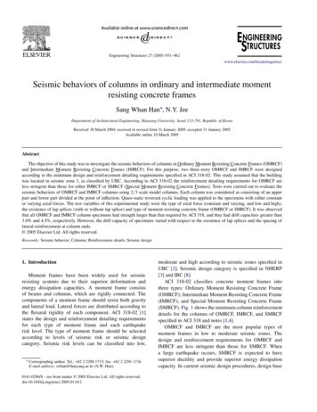
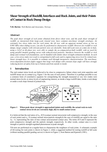
Shear Strength of Rockfill, Interfaces and Rock Joints, and their Pointsof Contact in Rock Dump DesignN.R. Bartonalso show roughness profiling, which is not only useful for rock joint characterisation, but also useful forinterface strength investigations.It can be noted from Figure 6 that the Schmidt hammer index test is used on rock joints to register what maybe a thin ‘skin’ of weathered rock with lower joint wall strength (JCS) than the ‘fresh’ rock uniaxialcompressive strength σc. This index test can also be used with advantage on rockfill materials, if stones aresuitably clamped when small enough to move under the impact of the spring-loaded ‘hammer’.Figure 83The range of joint roughness profiles tested, and their JRC values, based on the peak shearstrength of 130 rock joints. Note the characteristics (JRC, JCS, φr) of three examplestrength envelopes (Barton and Choubey, 1977). The units of JCS are (also) MPaThe shear strength of rockfill as measuredLeps (1970) is responsible for assembling a significant number of large-scale triaxial shear test data forrockfills of various types. The interpreted peak effective friction angles as a function of the estimatedeffective normal stress are shown in Figure 9a. We can ‘fit’ familiar values of JRC and JCS for rock joints(Figure 9b) that closely match the stress-dependent friction angles that (also) describe the shear strength ofrockfills. Mid-range JRC values (to correspond to an R-range of about 5 to 10, and low-to-high range JCSvalues (to correspond to an S-range of about 10 to 100 MPa) generated by medium weak to medium strongrock are seen to fit the test data. The more conventionally plotted shear stress versus effective stress curvesfor rockfill, shown in Figure 10 from Marsal (1973), also confirm the similarities of the peak shear strengthof rock joints and rockfill.8Rock Dumps 2008, Perth, Australia
Geotechnical Issues – Strength, Stability and SeepageFigure 9Left: Assembly of peak shear strength data for rockfills, from Leps (1970). Right:Comparative JRC or R, and JCS or S values used to generate similar gradients to Leps1970 data for rockfill. R 5 to 10, and S 10 to 100 MPa appear to cover the range ofstrengths assembled by Leps. Less compacted rock dump materials will tend to have lower‘R-values’ than the ‘tightly-packed’ particles, since there will generally be less interlockingFigure 10 The peak shear strength envelopes for rockfill have remarkable similarity to those formedium rough, medium strength rock joints. Large-scale test data from Marsal (1973)Rock Dumps 2008, Perth, Australia9
Shear Strength of Rockfill, Interfaces and Rock Joints, and their Pointsof Contact in Rock Dump DesignN.R. BartonFigure 11 Large rock dumps are a familiar feature of mines in the Chilean Andes. Large-scaletriaxial shear tests performed in Chile, with important results (black dots and Mohrcircles) showing non-linear stress-dependent friction angles (Linero and Palma (2006),reproduced with kind permission)The large scale measurement of frictional strength of rock dump materials obtained from mines in theChilean Andes shown in Figure 11 tend to further reinforce the idea of non-linear stress-dependent frictionangles that are likely to apply to rock dumps in general (priv. comm., Sandra Linero, SRK).10Rock Dumps 2008, Perth, Australia
Geotechnical Issues – Strength, Stability and SeepageFigure 12 The same non-linearity with effective stress level is seen in large-scale triaxial testsperformed at NGI (Strøm, 1974, 1975, 1978), with particle size-dependence, rock strengthdependence, and porosity effects also indicatedFor comparison, Figure 13 shows shear strength envelopes for rock joints that have been generated with theJRC-JCS model introduced in Figure 5. The strongly varying peak dilation angles, part of the reason for thenon-linearity, are also shown on each envelope, except at lowest stress, where they may exceed 30 .Figure 13 Shear strength envelopes (and peak dilation angles) predicted for rock joints, using theJRC-JCS non-linear model of Figure 5. Rockfill generally lies between curves #2 and #3Rock Dumps 2008, Perth, Australia11
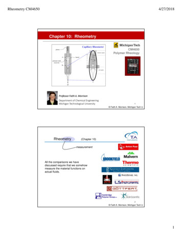
Shear Strength of Rockfill, Interfaces and Rock Joints, and their Pointsof Contact in Rock Dump Design4N.R. BartonEstimating the shear strength of rockfillAs emphasised in all reports of rockfill shear strength, including Barton and Kjærnsli (1981), the degree ofcompaction and porosity achieved when building a dam or when preparing relevant laboratory samples is allimportant. The particle roughness and smoothness is also fundamental. Figure 14 illustrates an empiricalscheme developed by the writer, for estimating the likely R-value for rockfills, whether for rounded gravelsor for rough quarried rock. The high (relatively uncompacted) porosities in mining rock dumps clearly placessuch dumps in the middle-to right-hand areas of this diagram, and even sharp angular particles (relevant forwaste rock, but perhaps not always for tailings) are unlikely to generate ‘R-values’ above 5 to 7, as alsosuggested in Figure 9.Figure 14 An empirical method for estimating the equivalent roughness R of rockfill as a function ofporosity and particle origin, roundedness and smoothness. Barton and Kjærnsli (1981)As a result of the literature survey of numerous rockfill test data, Barton, 1980 and Barton and Kjærnsli,1981 developed a simple strength factoring scheme for estimating S as a function of UCS (or σc), whenparticle size (d50) varied over a wide range. The points A and B in Figure 15 were used to illustrate S-valueestimation for a rock with UCS 150 MPa, when d50 was 23 mm (S 0.3x150 50 MPa) and when d50 was240 mm (S 0.2x150 30 MPa), in the case of interpreting triaxial strength data. Note the higher factorsapparently needed when planar (and large-scale) shear is involved. Friction angles are typically several12Rock Dumps 2008, Perth, Australia
Geotechnical Issues – Strength, Stability and Seepagedegrees higher (e.g. about 2 to 4 ) when plane tests are compared with triaxial tests on the same material.There is noticeably less crushing of particles: hence the two empirical curves in Figure 15.Figure 15 Particle size strongly effects the strength of contacts points in rockfill. Triaxial or planeshear also influences behaviour. Empirical S/UCS reduction factors for estimating S whenevaluating equation 3.5Interface shear strengthInterface shear strength, as between a (too smooth) rock foundation and a rockfill dam, seems to be governedby the ‘weakest link’ rule. If the roughness JRC of the interface, registered by amplitude/length profiling, istoo low in relation to particle size (d50), the interface strength is controlled by JRC, and sliding occurs alongthe interface, as along the bottom face of a rock joint. If on the other hand, the interface roughness issufficient to give good interlock to the rockfill particles, sliding will occur preferentially within the rockfill,in an ‘R-controlled’ particle smoothness or roughness dependent manner, with influence also of the porosity.A schematic illustration of the interface problem, and (probable) relevant controlling parameters is shown inFigure 16.Rock Dumps 2008, Perth, Australia13
Shear Strength of Rockfill, Interfaces and Rock Joints, and their Pointsof Contact in Rock Dump DesignN.R. BartonFigure 16 Asperity contact across stressed rock joints, and rockfill inter-particle contact, and rockfilllying on a rock foundation, are each examples of point-contact stress levels that areprobably close to compressive failure, when peak shear strength is approached. For thisreason the three cases have many points in common, including similar non-linear shearstrength envelopesThe peak shear strengths for rock joints, rockfill and interfaces are respectively:Rock joints:τ σ n tan ( JRC log JCS / σ n φ r )(2)τ σ n tan (R log S / σ n φ r )(3)τ σ n tan ( JRC log S / σ n φ r )(4)Rockfill:Interface:If the rockfill particles are not weaker than the rock foundation, as assumed in equation 4, then S JCS, andthe strength is determined by the weak foundation. In the case of rockfill or waste rock that is freshly blasted,the residual friction angle φr assumed, can (initially) be replaced by φb, which is usually a few degrees higherthan the weathered value. Conservative, long-term design strength may nevertheless demand the use of φr for‘permanent’ rock dumps and rockfill dams, as suggested in all three equations.14Rock Dumps 2008, Perth, Australia
Geotechnical Issues – Strength, Stability and Seepage5.1R-controlled or JRC-controlled behaviourAs indicated above, the relative magnitudes of the interface parameters, and their possible contrast to theshear strength of the rockfill, will determine whether the interface (if very rough) causes ‘R-controlled’behaviour – meaning preferential failure through the rockfill, or ‘JRC-controlled’ behaviour, meaningpreferential shear along the interface. A review of interface tests, performed by Barton (1980) in response todoubts about the strength of a glacially-smoothed dam foundation in Norway, resulted in the separation ofperformance identified in Figure 17.Figure 17 A review of interface shear tests was performed in response to concern over insufficientroughness for the rockfill dam foundation, in the glaciated mountain terrain in Norway.This review resulted in the JRC-R separation seen here. Squares and circles are datapoints derived from interpretation of relevant tests reported in the literature(Barton, 1980)Rock Dumps 2008, Perth, Australia15
Shear Strength of Rockfill, Interfaces and Rock Joints, and their Pointsof Contact in Rock Dump DesignN.R. BartonFigure 18 Simple demonstration of the differences between JRC-controlled and R-controlledbehaviour, which can also be demonstrated by tilt testingFigure 19 The Svartevann dam in Norway has limited roughness in parts of its steep glaciatedabutments. The a/L versus d50 ratios for this dam are not known however. These governingparameters were estimated for the Oddatjørn dam in another actually less glaciatedlocation (Barton, 1980)16Rock Dumps 2008, Perth, Australia
Geotechnical Issues – Strength, Stability and SeepageConclusions Rock joints, rockfill (and rock dumps), and interfaces between rock and rockfill have relatedgeotechnical behaviour, because they have ‘points-of-contact’ in common. The common denominator is very high rock-to-rock contact stress at the numerous points of contact. The important geotechnical result is a shared tendency for very non-linear, stress-dependent shearstrength. It is therefore extremely likely that rock dumps of different heights will have widely different factorsof safety – if formed with equal slope angles.ReferencesBarton, N. and Choubey, V. (1977) The shear strength of rock joints in theory and practice. Rock Mechanics 1/2:1-54.Vienna: Springer.Barton, N. (1980) Evaluation of shear strength in rockfill and between rockfills and rock foundations. NGI report53101-2, 67 p. (In Norwegian).Barton, N. and Kjærnsli, B. (1981) Shear strength of rockfill. J. of the Geotech. Eng. Div., Proc. of ASCE, Vol. 107:GT7: 873-891. Proc. Paper 16374, July.Barton, N. (1999) General report concerning some 20th Century lessons and 21st Century challenges in applied rockmechanics, safety and control of the environment. Proc. of 9th ISRM Congress, Paris, 3: 1659-1679, Balkema,Netherlands.Leps, T.M. (1970) Review of the shearing strength of rockfill. J. of Soil Mech. and Found. Div., ASCE, Vol.96, No.SM4, Proc. Paper 7394, July 1970, 1159-1170.Linero, S. and Palma, C. (2006) Caracterización geotecnica de materiales estériles para diseño de depósitos mineros degran altura. (Geotechnical characterization of rock materials for design of high rock dumps). Proc. of VI th SouthAmerican Rock Mechanics Congress., Cartagena, Colombia.Marsal, R.J. (1973) Mechanical properties of rockfill. Embankment-Dam Engineering, Casagrande Volume, eds.Hirschfeld and Poulos, J. Wiley and Sons, New York, pp. 109-200.Strøm, E. (1974), (1975) and (1978) NGI internal reports on triaxial testing of rockfill for various dams in Norway.Rock Dumps 2008, Perth, Australia17
Shear Strength of Rockfill, Interfaces and Rock Joints, and their Points of Contact in Rock Dump Design N.R. Barton Nick Barton and Associates, Norway Abstract The peak shear strength of rock joints obtaine