Transcription
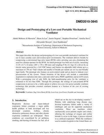
Proceedings of the 2010 Design of Medical Devices ConferenceDMD2010April 13-15, 2010, Minneapolis, MN, USAProceedings of the 2010 Design of Medical Devices ConferenceDMD2010April 13-15, 2010, Minneapolis, MN, USADMD2010-3845DMD2010-3845Design and Prototyping of a Low-cost Portable MechanicalVentilatorAbdul Mohsen Al Husseini1, Heon Ju Lee1, Justin Negrete1, Stephen Powelson1, Amelia Servi1,Alexander Slocum1, Jussi Saukkonen21Massachusetts Institute of Technology, Department of Mechanical Engineering2Boston University, School of MedicineAbstractThis paper describes the design and prototyping of a low-cost portable mechanical ventilator foruse in mass casualty cases and resource-poor environments. The ventilator delivers breaths bycompressing a conventional bag-valve mask (BVM) with a pivoting cam arm, eliminating theneed for a human operator for the BVM. An initial prototype was built out of acrylic, measuring11.25 x 6.7 x 8 inches (285 x 170 x 200 mm) and weighing 9 lbs (4.1 kg). It is driven by anelectric motor powered by a 14.8 VDC battery and features an adjustable tidal volume up to amaximum of 750 ml. Tidal volume and number of breaths per minute are set via user-friendlyinput knobs. The prototype also features an assist-control mode and an alarm to indicate overpressurization of the system. Future iterations of the device will include a controllableinspiration to expiration time ratio, a pressure relief valve, PEEP capabilities and an LCD screen.With a prototyping cost of only 420, the bulk-manufacturing price for the ventilator isestimated to be less than 200. Through this prototype, the strategy of cam-actuated BVMcompression is proven to be a viable option to achieve low-cost, low-power portable ventilatortechnology that provides essential ventilator features at a fraction of the cost of existingtechnology.Keywords: Ventilator, Bag Valve Mask (BVM), Low-Cost, Low-Power, Portable and Automatic1. IntroductionRespiratory diseases and injury-inducedrespiratory failure constitute a major publichealth problem in both developed and lessdevelopedcountries.Asthma,chronicobstructive pulmonary disease and other chronicrespiratory conditions are widespread. Theseconditions are exacerbated by air pollution,smoking, and burning of biomass for fuel, all ofwhich are on the rise in developing countries1,2Patients with underlying lung disease maydevelop respiratory failure under a variety ofchallenges and can be supported mechanicalventilation. These are machines whichmechanically assist patients inspire and exhale,allowing the exchange of oxygen and carbondioxide to occur in the lungs, a process referredto as artificial respiration3. While the ventilatorsused in modern hospitals in the United States are1Reprinted with permission ofAbdul Mohsen Al Husseini, Heon Ju Lee, Justin Negrete, Stephen Powelson, Amelia Servi, Alexander Slocum, Jussi Saukkonen
inexpensive portable ventilator forproduction can be scaled up on icated, their acquisition costs arecorrespondingly high (as much as 30,000).High costs render such yexpensive for use in resource-poor countries.Additionally, these ventilators are often fragileand vulnerable during continued use, . In developing countries, this hasled to practices such as sharing of ventilatorsamong hospitals and purchasing of less reliablerefurbished units. Since medical resources inthese countries are concentrated in major urbancenters, in some cases rural and outlying areashave no access at all to mechanical ventilators.The need for an inexpensive transport ventilatoris therefore paramount.which1.1. Prior ArtWhile many emergency and portable ventilatorsare on the market, an adequate low-costventilator is lacking. A cost-performancedistribution is depicted in Figure 1 withmanually operated BVMs on the low end of costand performance, and full-featured hospitalventilators on the other extreme. The middlesection of the chart includes the existing portableventilators which can be broadly categorized aspneumatic and electric. Pneumatic ventilatorsare actuated using the energy of compressed gas,often a standard 50 psi (345 kPa) pressuresource normally available in hospitals. Theseventilators have prices ranging from 700-1000.This category includes products such as theVORTRAN Automatic Resuscitator (VAR ), asingle patient, disposable resuscitator, and thereusable Lifesaving Systems Inc.'s Oxylator, OTwo CAREvent Handheld Resuscitators andAmbu Matic. However, these systems cost anorder of magnitude more than our target priceand depend on external pressurized air, aresource to which our target market may nothave access.In the developed world, where well-stockedmedical centers are widely available, theproblem is of a different nature. While there areenough ventilators for regular use, there is a lackof preparedness for cases of mass casualty suchas influenza pandemics, natural disasters andmassive toxic chemical releases. The costs ofstockpiling and deployment of state-of-the-artmechanical ventilators for mass casualty settingsin developed countries are prohibitive.According to the national preparedness planissued by President Bush in November 2005, theUnited States would need as many as 742,500ventilators in a worst-case pandemic. Whencompared to the 100,000 presently in use, it isclear that the system is lacking4. One exampleof this shortage occurred during HurricaneKatrina, when there were insufficient numbersof ventilators 5 , and personnel were forced toresort to manual BVM ventilation6. Measures toimprove preparedness have since been enacted;most notably the Center for Disease Control andPrevention (CDC) recently purchased 4,500portable emergency ventilators for the strategicnational stockpile 7 . However, considering thelow number of stocked ventilators and theircurrently high cost, there is a need for anFigure 1: Cost-performance distribution of ventilators2
of mechanical, medical, economic, s were developed. These include theASTM F920-93 standard requirements9, and aresummarized in Table 1.Electric ventilators are capable of operatinganywhere, and thus are not bound by thisconstraint. Ventilators of this type such asCareFusion LTV 1200 were the choice of theCDC for the Strategic National Stockpile. TheLTV 1200 weighs 13.9 lbs (6.3 kg) andincludes standard features as well as thecapability to slowly discontinue or wean offmechanical ventilator support. Its complexityelevates its cost to several thousands of dollars,an order of magnitude above our target retailprice.Medical-The United States Department of Defense hasalso developed several rugged, portable electricventilators. One such ventilator is the JohnsHopkins University (JHU) Applied PhysicsLaboratory (APL) Mini Ventilation Unit(JAMU), which weighs 6.6 lbs (3.0 kg),measures 220 cubic inches (3,600 cubic cm) andcan operate up to 30 minutes on a battery. Thisdevice was patented by JHU/APL, and licensedto AutoMedx. The commercial device featuressingle-knob operation. Its simplicity comes witha compromise, as the tidal volume, breath rateand other parameters cannot be adjusted by theuser, making it not suitable for many patientswho cannot tolerate the fixed tidal volume, rateor minute ventilation. It also cannot be operatedfor long periods in a resource-poor environment.Additionally, with a price tag over 2000, itcosts several times more than our target price.Another device, the FFLSS, weighs 26.5 lbs (12kg) and is capable of one hour of operationpowered by a battery. It also includes additionalphysiologic sensors, and fits in a standard U.S.Army backpack 8 . While these devices arefunctionally adequate, their compressors requirehigh power which limits battery life. In addition,their many pneumatic components are costly andare not easily repairable in a nterfaceRepeatability-User-specified breath/mininsp./exp ratio, tidal volumeAssist controlPositive end-expiratorypressure (PEEP)Maximum pressure limitingHumidity exchangeInfection controlLimited dead-spacePortableStandalone operationRobust mechanical,electrical and softwaresystemsReadily sourced andrepairable partsMinimal power requirementBattery-poweredLow-cost ( 500)Alarms for loss of power,loss of breathing circuitintegrity,highairwaypressure and low batterylifeDisplay of settings andstatusStandard connection portsIndicators within 10% ofcorrect readingBreath frequency accurateto one breath per minuteTable 1: Device functional requirements2. Device Design2.1. Air Delivery TechniqueTwo main strategies were identified for theventilator’s air delivery system. One strategy1.2. Medical Device RequirementsIn light of the aforementioned constraints, a set3
uses a constant pressure source to intermittentlydeliver air while the other delivers breaths bycompressing an air reservoir. The latter approachwas adopted as it eliminates the need for thecontinuous operation of a positive pressuresource. This reduces power requirements andthe need for expensive and difficult to repairpneumatic components.space. Other compression techniques weresought to take advantage of the cylindrical BVMshape. However, since BVMs were designed formanual operation, their compressible outersurface is made from high-friction material tomaintain hand-contact with minimal slippage.This eliminates the option of tightening a strapwrapped around the bag as a means of actuation.To avoid the problems associated with highsurface friction, the two main candidates foractuation were a roller chain and camcompression. These options employ rollingcontact with the bag rather than sliding contact,eliminating losses due to kinetic frictionbetween the actuator and the bag.Where most emergency and portable ventilatorsare designed with all custom mechanicalcomponents, we chose to take an orthogonalapproach by building on the inexpensive BVM,an existing technology which is the . Due to the simplicity of their designand their production in large volumes, BVMsare very inexpensive (approximately 10) andare frequently used in hospitals and ambulances.They are also readily available in developingcountries. Equipped with an air reservoir and acomplete valve system, they inherently providethe basic needs required for a ventilator.2.2.1. Roller-chain ConceptThe roller-chain concept utilizes roller-chainswith roller diameters larger than link width.(Figure 2) The chain wraps around thecircumference of the bag, and as a result is veryspace efficient. A sprocket connects to the motorshaft; its clockwise/anticlockwise rotationcompressing and expanding the bag for breathdelivery.The main drawback with BVMs is their manualoperation requiring continuous operatorengagement to hold the mask on the patient andsqueeze the bag. This operating procedureinduces fatigue during long operations, andeffectively limits the usefulness of these bags totemporary relief. Moreover, an untrainedoperator can easily damage a patient’s lungs byover compression of the bag. Our methodology,therefore, was to design a mechanical device toactuate the BVM. This approach results in aninexpensive machine providing the basicfunctionality required by mechanical ventilatorstandards.2.2. Compression MechanismThe most obvious means to actuate a BVM is tomimic the hand motion for which the bag wasdesigned. This requires the use of linearactuation mechanisms (e.g. lead screw or rackand pinion) which despite being simple toimplement, require linear bearings and extraFigure 2: Sketch of roller-chain deviceWhile this idea seemed initially feasible,preliminary experiments revealed that radialcompression of a BVM requires significantlyhigher force than the vertical compression forwhich the bag was designed. Additionally, its4
3. Prototype Designoperation was noisy, and the bag crumpledunder radial compression, inhibiting the desiredpure rolling motion, and preventing an accurateand repeatable tidal volume from beingdelivered.3.1. First Prototype DesignWith the cam concept selected as the bestmethod for BVM compression, an initialprototype was built to measure force and powerrequirements. The enclosure’s frame consists offour vertically mounted sections of ½” (12.5 mm)clear acrylic, each mounted on the bottomsection of the frame with interlocking mates.The material is easily laser cut and allows forvisibility of the internal components. The twoinner sections (ribs) have U-shaped slots madeto conform to BVM’s surface contour, while theend sections feature openings to accommodatethe BVM’s valve neck and oxygen reservoir.The pivoting cam assembly was mounted on topof the hinged aluminum lid, and consisted of two2.5" (63.5 mm) radius crescent-shaped piecesattached to a 5/16" (8 mm) aluminum shaftmounted with nylon bushings.A trade-off was encountered; while smallpitch/roller-diameter chains are more spaceefficient and yield higher angular resolution forcompression, bag crumpling becomes an issue.On the other hand, a higher pitch/roller-diameterchain overcomes crumpling but takes up morespace and decreases angular resolution. In eithercase, the use of roller chains added a significantamount of weight to the system suggesting theneed for a more effective mechanism needing asmaller contact area.2.2.2. CAM ConceptThe cam concept utilizes a crescent-shaped camto compress the BVM, which allows smooth,repeatable deformation to ensure constant airdelivery (Figure 3). As it rotates, the cam makesa rolling contact along the surface of the bag andunlike the roller-chain, achieving low-noise of3.2. First Prototype ExperimentA bench level experiment was conducted on thefirst prototype to determine performancecharacteristics. Data was collected using ourprototype's cam mechanism to compress an adultsized Ambu BVM. The test apparatus includeda spirometer to measure flow-rate (and volume,by integrating over time), a hand dynamometerto measure force exerted on the cam, a rotarymotion sensor to measure cam angulardisplacement, and a pressure sensor to measureinternal air pressure. The experimental setup isdepicted in Figure 4 and 5.Figure 3: Sketch of cam based deviceoperation. By controlling the angle of the cam’sshaft, the amount of air volume delivered can beaccurately controlled. The cam mechanism wasfound to be more space efficient and have alower power requirement than the roller chainconcept, and was therefore the method of choice.Figure 4: Sketch of experiment setup5
of acrylic, and hinges from the side of the unit tobetter constrain the top of the bag. The supportribs inside the enclosure also serve as mountingblocks for camshaft bushings. A potentiometerwas coupled to the end of the shaft for use as aposition feedback sensor. An isometric view ofthe second prototype’s CAD model is shown inFigure 7, and the built device in Figure 8.Figure 5: Actual experiment setupThe air volume delivered was measured as afunction of cam angle by integrating the flowrate over time. Results indicated that the volumedelivered versus cam angle relation isapproximately linear (Figure 6). Data analysisshowed that the peak power required was 30 W,and maximum torque was 1.5 Nm. Themaximum volume delivered per stroke wasapproximately 750 mL. The target tidal volumeis 6-8 ml/kg for adult human use, so this isadequate for most clinical situations.Figure 7: Second prototype CAD modelFigure 8: Second prototypeFigure 6: Volume vs. Cam angle4. Control Implementation4.1.Control designThis ventilator provides assured tidalvolumes using an assist-control (AC) mode.The operator selects the tidal volume appropriateto the patient, usually 6-8 mL/kg of ideal bodyweight and a minimum respiratory rate. Thisprovides a minimum assured minute ventilation(Ve). If the patient is breathing above the set3.3. Second Prototype DesignA second prototype was built in which all themoving components were moved inside theenclosure. Enclosure dimensions were increasedto accommodate the cam arm’s range of motion,and to make space for the motor, microcontrollerand battery pack. The enclosure’s lid was made6
4.3. ntroller board was selected to controlour device. The microcontroller runs a simplecontrol loop to achieve user-prescribedperformance.rate, negative inspiratory pressure that exceeds 2cmH20 vacuum triggers the ventilator to deliverthe set tidal volume.The advantage of AC mode is that the patienthas an assured minute ventilation to meetphysiologic needs for adequate gas exchange. Adisadvantage is that if the patient is tachypneicor breathing too fast, respiratory alkalosis maydevelop or, for those with obstructive lungdisease, air trapping may occur, raising intrathoracic pressure with adverse hemodynamicand gas exchange consequences. However, theseissues are commonly handled with reductions inrespiratory rate and sedation as needed. ACmode, one of the most widely utilizedmechanical ventilator modes, is adequate for themanagement of the majority of most clinicalrespiratory failure scenarios. This ventilator canbe used for patients who are intubated with anendotracheal tube or who would receive noninvasive mechanical ventilation through a maskthat is commonly used for provision ofcontinous positive airway pressure (CPAP).The control loop is triggered by the internaltimer set by user inputs, with the inspiratorystroke initiated at the beginning of the loop.Once the prescribed tidal volume is reached, theactuator returns the cam back to its initialposition and holds until the next breath. Theloop then repeats to deliver intermittent breaths.If the loop is interrupted by a breath attempt bythe patient (sensed through the pressure sensor),the ventilator immediately delivers a breath,interrupting the loop and resetting the timer. Adiagram showing this loop is found in Figure 9.4.2. ParametersThe operator adjusts tidal volume, breath rate,and inspiratory to expiratory time ratio usingthree continuous analog knobs mounted to theoutside of the ventilator. The prototype has arange of 200-750 mL tidal volume and 5-30breaths per minute (bpm).This yields amaximum minute ventilation (Ve) of 21L and aminimum Ve of 1.5L. However, these values donot reflect the limits of the final design only thesettings of the prototype. Theoretically, theventilator is able to deliver anywhere from 0Lminute volume to 60L minute volume. However,this has not been fully tested. I:E ratio was notimplemented on the prototype but theoreticallycould have any desired range within the limitsdetermined by the other parameters. The rangeson the final design will be determined inconsultation with respiration specialists to allowfor the broadest range of safe settings.Figure 9: Ventilator control loop4.4. MotorAccording to initial experiments, a maximumtorque of 1.5 Nm was required for maximumvolume delivery. A PK51 DC gearmotor with astall torque of 2.8 Nm was selected for theprototype. Despite the lower torque valuemeasured in our experiment, we found that thismotor did not provide quite enough torque toeffectively drive the cam at the slower inhalationcycle rates prescribed to some patients. While alarger motor will be necessary to achieve betterspeed control, this motor functioned acceptably7
at the proof-of-concept phase. It was desirablefor its gear reduction ratio of 51:1, and anoperating speed in the required range of 50-70rpm.the ventilator can run off of any battery capableof delivering 12-15 volt at least 3.5 Amps. Forthe prototype, we used a 14.8 volt, four-cell LiIon battery pack capable of 4.2 Amps (limitedby protective circuitry), with a capacity of 2200mA-hr.4.5. Motor DriverThe motor driver comprises of two H-Bridgecircuits. These circuits direct current through themotor in opposite directions, depending onwhich set of switches on the circuits areenergized. Speed of the motor is signaled with apwm pin. The power is supplied directly fromthe battery, so the only limit is the currentcapability of the chip and battery.5. Analysis and Testing5.1. Battery-life TestThe battery life for the second prototype wastested by running the ventilator on the test lunguntil the battery voltage dropped to a levelinsufficient for operation. The device was set atmaximum volume and BPM rate (30breaths/minute). The overall duration of the testwas three hours and thirty-five minutes at whichpoint the battery was depleted. Based on thebattery capacity and voltage, the electrical powerconsumption during this test averages to only 9Watts (this includes the inactive time betweenbreaths).We opted to use the Solarbotics motor driver,which is capable of supplying 5 amps of currentto the two circuits. The PK51 motor's stallcurrent is rated at 5.2 amps which means themotor driver will be able to handle therequirements for the system.4.6. User InterfaceThe three user inputs (tidal volume, bpm and I:Eratio) are set via three potentiometer knobs.Future iterations of the device will include theaddition of an LCD display to show the inputsettings as well as airway pressure level andbattery power status.6. ConclusionsA working prototype that can be operated on atest lung has been developed. The prototype hasuser-controlled breath rate and tidal volume. Itfeatures assist control and an over-pressurealarm. It has low power requirements, runningfor 3.5 hours on one battery charge at its mostdemanding setting. It is portable, weighing 9 lbs(4.1 kg) and measuring 11.25 x 6.7 x 8 inches(285 x 170 x 200 mm) , and has a handle andeasy to use latches. The prototype can displaysettings and status on a computer screen.4.7. Safety FeaturesTo ensure that the patient is not injured, theairway pressure is monitored with a pressuresensor connected to a sensor output on the BVM.The same pressure sensor used for initiation ofassist control also triggers an alarm if thepressure rises too high, alerting the physician toattend to the patient. As a further safety measureto prevent over-inflation, future iterations of thedevice will include a mechanical pressure reliefvalve.Further development of this proof-of-concept isplanned. Future iterations will incorporatechanges prompted by the results of our prototypetesting.It will incorporate an adjustableinspiratory to expiratory ratio, an option missingin this prototype due to its underpoweredmotor. We will investigate the effects thatchanging the motor will cause to cost, weight4.8. Power DeliveryAn AC/DC converter can be used to power theventilator directly from a wall outlet or a vehicleinverter. When external power is unavailable,8
create the models for this project.and battery life. We will also incorporate addon features including a PEEP valve, a humidityexchanger and a blow-off valve. Since BVMinfrastructure already supports commercial addons, these components can be easily purchasedand incorporated. Ways to minimize deadspacewill be explored, including the option of using aLaerdal brand BVM whose valves can beplaced at the patient end of the tubing. In lateriterations we hope to be independent fromLaerdal by manufacturing our own bags orcontracting their production. The design will bechanged to be injection molded such that themass-produced a version would cost less than 200 to produce. Weight will be minimized andbattery-life extended.Consideration to apediatric version will also be given. Cam armshape will be optimized to ensure the use of themost efficient rolling contact embodiment. AnLCD screen will be included, and alarmsprogrammed for loss of power, loss of breathingcircuit integrity and low battery life. Extensivetesting of the ventilator's repeatability will beconducted. Finally, we will test the ventilator ona lung model to meet ventilator standards andmarket the product.8. References[1] Aït-Khaled N, Enarson D, Bousquet J (2001)Chronic respiratory diseases in developingcountries: the burden and strategies forprevention and management, Bulletin of theWorld Health Organization, 79 (10)[2] Chan-Yeung M, Aït-Khaled N, White N, Ip MS,Tan WC (2004) The burden and impact ofCOPD in Asia & Africa. Int J Tuberc Lung Dis.[3] Webster's New World Medical DictionaryFirst, Second and Third Editions (May, 2008)John Wiley & Sons, Inc.[4] McNeil, DG (2006) Hospitals short ofventilators if bird flu hits, NYT, May 12[5] Klein KR, Nagel NE (2007) Mass medicalevacuation: Hurricane Katrina and nursingexperiences at the New Orleans airport. DisasterManag Response. 2007 Apr-Jun;5(2):56-61[6] deBoisblanc, B.P. (2005) Black Hawk, pleasecome down: reflections on a hospital's struggleto survive in the wake of Hurricane Katrina. AmJ Respir Crit Care Med. Nov 15;172(10):123940[7] rgency.aspx7. AcknowledgementsThe design and fabrication of this device was aterm project in MIT Course 2.75: PrecisionMachine Design. We are grateful to LynnOsborn and Dr. Tom Brady of The Centerfor Integration of Medicine and InnovativeTechnology www.cimit.org for providingsupport for course 2.75 and this project; and theVA Medical Center-West Roxbury. CIMITsupport comes from DOD funds with FAR52.277-11. Special thanks are due to Prof. AlexSlocum, Nevan Hanumara, Conor Walsh andDave Custer for continuous guidance for theproject. We are also thankful to Dr. BarbaraHughey for her help with instrumentation for ourbench level experiments. The authors would alsolike to thank SolidWorks Corporation forproviding the solid model software used to[8] Kerechanin CW, Cytcgusm PN, Vincent JA,Smith DG, Wenstrand DS (2004) Developmentof Field Portable Ventilator Systems forDomestic and Military Emergency MedicalResponse, John Hopkins Apl. Tech. Digest Vol25, Number 3[9] ASTM F920-93(1999)23456789
1.1. Prior Art While many emergency and portable ventilators are on the market, an adequate low-cost ventilator is lacking. A cost-performance distribution is depicted in Figure 1 with manually operated BVMs on the low end of cost and performance, and full-featured hospital ventilators on the other extreme. The middle