Transcription
DIRECT SHEAR TESTSOIL MECHANICSSOIL MECHANICS LABORATORYDEPARTMENT OF CIVILENGINEERINGUNIVERSITY OF MORATUWASRI LANKA
DIRECT SHEAR TESTOBJEVTIVESTo determine the shear strength parameters for a given soil using the direct shear test.INTRODUCTIONThe test is carried out on either undisturbed samples or remoulded samples. To facilitate theremoulding purpose, a soil sample may be compacted at optimum moisture content in acompaction mould. Then specimen for the direct shear test could be obtained using the correctcutter provided. Alternatively, sand sample can be placed in a dry state at a required density, inthe assembled shear box.A normal load is applied to the specimen and the specimen is sheared across the pre-determinedhorizontal plane between the two halves of the shear box. Measurements of shear load, sheardisplacement and normal displacement are recorded. The test is repeated foe two or moreidentical specimens under different normal loads. From the results, the shear strength parameterscan be determined.THEORYThe strength of a soil depends of its resistance to shearing stresses. It is made up of basically thecomponents;1. Frictional – due to friction between individual particles.2. Cohesive - due to adhesion between the soil particlesThe two components are combined in Colulomb’s shear strength equation,τf c σf tan øWhere τf shearing resistance of soil at failurec apparent cohesion of soilσf total normal stress on failure planeø angle of shearing resistance of soil (angle of internal friction)This equation can also be written in terms of effective stresses.
τf c’ σ’f tan ø’Where c’ apparent cohesion of soil in terms of effective stressesσ'f effective normal stress on failure planeø’ angle of shearing resistance of soil in terms of effective stressesσ'f σf - ufuf pore water pressure on failure planePROCEDURE1. Assemble the shear box2. Compact the soil sample in mould after bringing it to optimum moisture condition3. Carefully transfer the sample into shear box
4. Place the loading plate on top of the upper porous plate. After recording the weight of theloading carrier place it is on the loading cap.5. Position all dial gauges and set the readings to zero. Remove the alignment screws whichhold two halves of the shear box together6. Tighten the remaining, two diagonally opposite screws, until there is a small gap betweenupper and lower boxes to reduce the frictional force7. Apply the desired normal load. If there is any vertical displacement, wait till the dialgauges indicate a constant reading and then reset the dial gauge to zero8. Check that screws have been removed and then start the motor to produce the desiredconstant rate of shearing
9. Take readings of,a) Shear load from the proving ringb) Shear displacement (i.e. Horizontal displacement)c) Vertical displacement at every 10 division increment in horizontal dial gauge10. Stop the test when the shear load starts to reduce or remains constant for at least threereadings11. Remove the soil and repeat the procedure with different normal loads at least for anothertwo samplesCOMPUTATION1. For each specimen plot the following;a. Shear stress Vs shear displacementb. Normal displacement Vs shear displacementc. Void ratio Vs shear displacement2. Plot the graph of shear strength Vs normal stress for the three specimens and calculate theshear strength parameters for the soil.REPORTYour report should include a brief but accurate description of the test procedure and all the abovementioned graphs. Also it should include a discussion of the followings;a) Importance of the shear strength in soilb) The normal displacement behavior of the specimen during shearingc) Different types of shear testsd) The main advantages and disadvantages of shear box teste) Reliability of the results and the factors most likely to influence the reliability
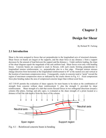
Department of Civil EngineeringUniversity of MoratuwaDirect Shear Test ResultsLoad Deformation ReadingsProject:Sample No. :Type of Test :Proving reading Constant Vertical Dial Gauge Constant:Normal Load Applied Horizontal Dial Gauge Constant :MoistureContent Mass of Wet sample Can (g) DeterminationMass of Dry sample Can (g) Mass of Can (g) Moisture Content (%) Shear Disp. ProvingVerticalChange in Void Ratio Shear force Sheardiv.RingDis.Void 25150175200225250275300325350375400425450475500
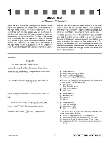
TEST :3Normal Stress 150 kN/m2Observations :Weight of shear box without sandWeight of shear box with sandTop plate dimensionsBottom plate dimensionsShear box dimensionsInternal height of the shear box(without sand)Internal height of the shear box(with sand)W1W2Ht1,Ht2Hb1,Hb2H1 60mm X 60 mm H2 Calculations:Thickness of the soil sample, H H1-H2-( Hb2- Hb1)/2- Ht2 (Ht2- Ht1)/2 Volume of the soil, V Weight of the soil sample, W W1-W2Dry Density of Soil sample, γd W/V Initial Void ratio, e0 GSγw/ γd – 1; GS 2.65 Specimen calculation for Vertical displacement/ Void ratio01 div. of vertical dial gauge readingCorresponding Void ratio change, eCorresponding Void ratio e e0 – eSpecimen calculation for Shear displacement 0.001x25.4mm 0.0254mm H (1 e0)/H
01 div. of horizontal dial gauge reading 0.01mmSpecimen calculation for Shear Force/ Shear stress01 div. of Proving ring reading Area correction for shear displacement Eg. For shear displacement div area Corresponding proving ring reading is Shear stress
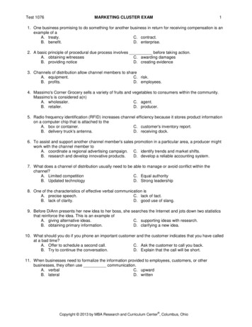
TEST :1Normal Stress 50 kN/mm2Observations :Weight of shear box without sandWeight of shear box with sandTop plate dimensionsBottom plate dimensionsShear box dimensionsInternal height of the shear box(without sand)Internal height of the shear box(with sand)W1W2Ht1,Ht2Hb1,Hb2H1 2.6652.9101.70mm, 3.44mm1.74mm, 3.26mm60mm X 60 mm43.60 mmH2 0mm H1-H2-( Hb2- Hb1)/2- Ht2 (Ht2- Ht1)/2 43.60-(3.26-1.74)/2-3.44 (3.44-1.70)/2 40.27mm 60x60x40.27 mm3 1.45x10⁻⁴ m3 W1-W2 2.910-2.665 kgDry Density of Soil sample, γd W/VInitial Void ratio, e0 GSγw/ γd – 1; GS 2.65 2.65x10³/1689.66 - 1 0.568Calculations:Thickness of the soil sample, HVolume of the soil, VWeight of the soil sample, W 0.245 /1.45x10-4 kg/ m3Specimen calculation for Vertical displacement/ Void ratio01 div. of vertical dial gauge readingCorresponding Void ratio change, eSpecimen calculation for Shear displacementCorresponding Void ratio e e0 – e 0.245 kg0.001x25.4mm0.0254mm H (1 e0)/H0.0254(1 0.568)/40.270.989x10-30.568 - 0.989x10-30.567
01 div. of horizontal dial gauge reading 0.01mmSpecimen calculation for Shear Force/ Shear stress01 div. of Proving ring reading 0.6lbs 0.6/2.206 0.272 kgkgArea correction for shear displacementarea 60 x (60-2) 3480 mm2Eg. For shear displacement 200 div 2mmCorresponding proving ring reading is 6 div 6 x 0.272 kg 1.632 kgShear stress 1.632/3480 kg/mm2 4.60 kN/ m2
Department of Civil EngineeringUniversity of MoratuwaDirect Shear Test ResultsLoad Deformation ReadingsProject:Sample No. :Type of Test :Proving reading Constant 0.6lbs/div.Vertical Dial Gauge Constant 0.001”2Normal Load Applied 18.34 kg (50 kN/m ) Horizontal Dial Gauge Constant 0.01mmMoisture Content DeterminationMass of Wet sample Can (g) Mass of Dry sample Can (g) Mass of Can (g) Moisture Content (%) ShearProving VerticalVerticalChange in 1914.856884425450475500
Stop the test when the shear load starts to reduce or remains constant for at least three readings 11. Remove the soil and repeat the procedure with different normal loads at least for another two samples COMPUTATION 1. For each specimen plot the following; a. Shear stress Vs shear displacement b. Normal displacement Vs shear displacement c. Void ratio Vs shear displacement 2. Plot the graph .