Transcription
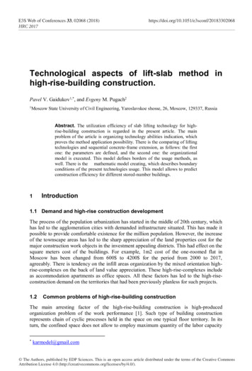
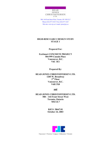
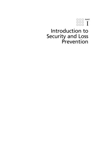
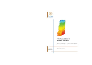
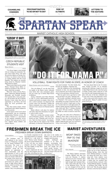
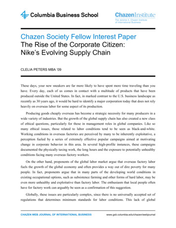
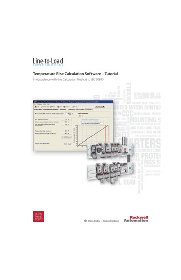
An Introduction to High-Rise DesignBy John Zils and John ViiseThe structural system of a high-rise buildingoften has a more pronounced effect than a lowrise building on the total building cost and thearchitecture. As a result, those faced with aninitial venture into tall building design needto be aware of concepts that are not emphasizedfor low-rise design.High-rise design comes into play when astructure’s slender nature makes it dynamicallysensitive to lateral loads, such that a premiumis associated with its lateral system development(Figure 1). The simplified model for thebehavior of a tall building is a vertical cantileverout of the ground. In this model, the momentof inertia of the cantilever is calculatedconsidering each of the vertical elements, suchas core walls and perimeter columns, active inthe lateral system. Deflection is due primarilyto axial shortening and elongation of theseelements.thgirypoCRTSDue to shear deformation, this idealizedstiffness is not fully achievable. A measure ofhow closely a system can approach the idealizedmodel is reported as a ratio of deflection ofthe ideal cantilever system to the actualdeflection, and is referred to as the building’scantilever efficiency. It is important whenselecting a system to realize where sheardeformation loss occurs and to ensure thatanalytical modeling techniques accuratelyaccount for it (Figure 2).maEach lateral system choice brings its ownpractical limits. For the two main structuralmaterials, steel and reinforced concrete,suggested practical ranges are illustrated inFigure 3. While steel systems offer speed inconstruction and less self-weight, therebydecreasing demand on foundations, reinforcedconcrete systems are inherently more resistantto fire and offer more damping and mass,which is advantageous in combating motionperception by occupants. Composite systemscan exploit the positive attributes of both.12UeT nCUFigure 1: High Rise PremiumgERaizFigure 2: Shear Deformation EffectsS T R U C T U R E m a g a z i n e November 2 0 0 3
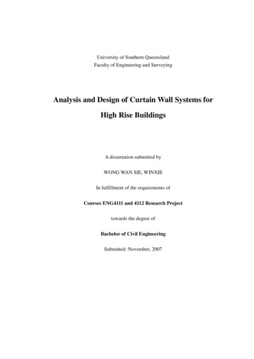
Because code prescribed equivalent staticwind loading cannot accurately predict the gusteffect on tall buildings or turbulence createdby adjoining buildings, wind tunnel tests areroutinely conducted. Gusting effects becomeespecially problematic and pronounced whenpulsating transverse loading, called vor texshedding, is created in tune with fundamentalperiods of the building (Figure 4).thgirypoCSmFigure 3: Practical Limits of Lateral SystemsaAlong with a system’s material choice, theissue of slenderness must also be considered.A measure of a building’s slenderness is theaspect ratio. For core wall only lateral systems,ratios typically range from 10:1 to 13:1. Forlateral systems that engage exterior elements,an aspect ratio up to 8:1 is feasible. Pushingthis ratio up to 10:1 can result in the need forspecial damping devices to mitigate excessivemotion perception. UeT nCURTWind loading is normally the governingloading in design of high-rise lateral systems.Conventionally, a maximum wind drift criteriaof H/500 is used. Drift is more importantwith a tall building due to significant secondorder effects it can produce (the additivegERWind tunnel testing considers appropriateloading for overall lateral system design andcladding design, and predicts motionperception and pedestrian level effects. In awind tunnel test, block models, scaled 1:300to 1:600, are incorporated into a proximitymodel on a turntable which includes buildingsand other obstructions from 300m to 800maround the building site. The turntable isadjusted to measure wind effects on thebuilding model for a full 360 degrees, takinginto account site specific directional behaviorof the winds.a izoverturning effect of the building mass appliedin its deflected shape). In a low-rise building,these effects may be negligible. However, intall building design the impact on deflectionand overturning moment can not beoverlooked. When considering P-delta effectsfor strength checks of the system, total factoredgravity loads are used. When consideringimpact on deflections, all self-weight, cladding,actual superimposed dead load and apercentage of live load, 10psf minimum, isconsidered.See the Wind Tunnel Testing articleon page 24 of this issue.Commonly, a high frequency force-balancetest is used to assess proper design wind loadsfor overall system design. This test measuresbase overturning and torsional moments bymodeling the building as a rigid element, takinginto account its fundamental sway and torsionalmodes of vibration. Intrinsically, the testassumes that the lowest sway modes of thebuilding are linear up the height of thebuilding. Where this is not the case, analyticaladjustments are made to test results.Ultimately, the test yields a series of wind loads(x, y and torsional) at each floor, and loadingdirection cases that take into account dynamiceffects for all wind directions.Although wind tunnel testing offers moreaccurate results, approximate wind and crosswind acceleration equations are included in theCanadian National Building Code. Generally,horizontal accelerations var y inverselyproportional to generalized mass, inverselyproportional to the square root of damping,and are less significantly correlated to theS T R U C T U R E m a g a z i n e November 2 0 0 313
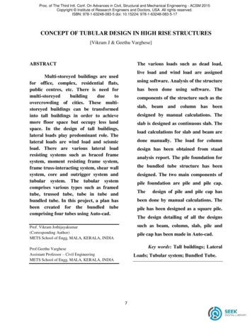
Higher return periods, the average timebetween the magnitude of event considered,are investigated for each component testedbased on the consequence of failure to meetthe design criteria. For example, in the overallsystem strength design, a 100 year wind maybe used while in the case of checking motionperception, a 10 year wind may be used.thgirypoCRTSUeT nCUFigure 4: Vortex Shedding ForcesmagERaThe effects of wind can be minimized byaerodynamic shaping of the building. In thecase of the proposed 2000’ tall 7 South Dearborn building in Chicago, the impact ofdynamic loads due to organized vortexshedding was reduced by rounding buildingedges, varying floor plate size, and introducingbuilding set-backs. One distinctive feature ofthe design introduced building slotdiscontinuities resulting in a reduction ofoverturning moments by approximately 15%(Figure 6).izIntrinsically, tall buildings have longerperiods and are not as sensitive as low-rises tohigh frequency seismic loading. A responsespectrum analysis is usually performed,regardless of the site seismic zone. In higherseismic zones special care is devoted to detailingto ensure system ductility.Once the conceptual lateral system is laidout and governing load cases are established,optimization methods can be employed toensure that structural material is distributedefficiently to lateral system components.Typically building elements are optimized tomeet a given drift target or to tune the buildingto meet a target sway period1,2.Due to the heavier loading, high-risefoundations are a major component of thedesign. Where possible, high-rise foundationsconsist of piles or caissons founded in solid rockor sub grade layers. Where soil conditions areFigure 5: Maximizing Generalized Mass14S T R U C T U R E m a g a z i n e November 2 0 0 3 stiffness and the period of the structure. As aresult, often the most cost-effective way toreduce building accelerations is by maximizinggeneralized mass (Figure 5).
poorer, special attention must be made toensure differential settlement values will nothave a detrimental effect. Differentialsettlement in high-rise foundations isespecially problematic because base rotationsproduce P-delta effects up the height of thebuilding. Pile stiffness, used in design,should accurately account for pile axialshortening, pile creep and shrinkage effectsfor sustained loads, and soil settlement.Foundation stability checks for sliding andoverturning should confirm a minimumfactor of safety of 1.5. In these checks,stabilizing effects of basement walls andpassive soil pressure against foundationelements and basement walls are taken intoaccount.A specified lease span, the distance fromthe core face to the inside face of buildingenclosure, will often be part of a tallbuilding’s design brief. Defined lease spansGlossaryLateral SystemStructural elements which resist seismic, wind and eccentric gravity loading.Braced TubeDistributes gravity and lateral loads along perimeter columns through the use ofconcentric bracing.Bundled TubeSystem of inter-locking frames consisting of closely spaced columns and deepgirders sized to behave as a tube and to limit impact of shear lag.Shear Lag(In a tube system) Loss of effective uniform stress distribution along perimeterframe line flanges as distance from shear frame line increases.Composite Stayed MastInterior reinforced concrete core tied to perimeter columns to increase structuraloverturning stiffness.Core WallReinforced concrete walls that enclose interior circulation core and resist seismic,wind and eccentric gravity loads.poCUeT n Aspect RatioCeiling SandwichFloor-to-floor section, produced in the conceptual phase, which identifiesrequired allowance zones for architectural, structural, and building services.Outrigger Trusses/WallsTrusses/walls which link interior core with perimeter lateral system elements.Usually coupled with belt trusses / walls at double story mechanical levels.Gust EffectExciting effect on a building due to turbulent wind.CUagaiz For Advertiser Information, visit www.structuremag.orgmER(In the context of a building lateral system) Any deformation which reduces thestiffness of the system from the ideal cantilever model.Measure of lateral system slenderness. For core wall only systems, measured as theratio of the building height to minimum dimension of the core wall. For systemsthat engage perimeter columns, ratio of height to the minimum out-to-out ofperimeter columns.RTSthgiryShear DeformationS T R U C T U R E m a g a z i n e November 2 0 0 315
are beneficial because they ensure that coreswill have long faces with aligned walls, therebyoffering maximum depth for lateral corebracing or core wall lines. Once the lease spanis established, optimization of the structuralframing system is important because anyreduction in the structural zone of the ceilingsandwich translates to significant savings overthe height of the building. In addition toefforts to reduce framing depths, options thatincorporate building service allowances withinthe structural zone (such as steel cellular beamsand composite steel floor trusses) are oftenpursued.Unlike most low-rise design, constructionschedules and sequencing can significantlyimpact design assumptions. A good exampleis the phenomenon of creep and shrinkage inreinforced concrete columns and walls. Inreinforced concrete high-rises, an effort is madeto equalize stress level to minimize this effect.Design must take into account adjustments andphasing that will be required, duringconstruction, to ensure a defined design loadflow and ultimate floor levelness.thgirySCUmThough this article is not long enough toaddress all of the issues that one might face inhigh-rise design, it offers a brief summary toget such projects started successfully. Anumber of good additional resources areavailable for those interested in moreinformation4,5. Because tall building designresults in larger computer analysis models as16ga izFigure 6: Aerodynamic Shaping of BuildingsaIssues of robustness and redundancy of ahigh-rise building system are generally left tothe discretion of the designer3. In BritishStandards and other codes such as the NewYork City building code, provisions to preventprogressive collapse are included. Redundancyis addressed by provisions that attempt todevelop alternate load paths in extreme events.Robustness is addressed by identification ofsystem key elements and specification of anextreme loading to be considered in theirdesign.UeT npoCRTER(Courtesy of Skidmore Owings & Merrill, LLP & James Steinkamp, Steinkamp Ballogg)compared to low-rise design, the mostimportant thing to keep in mind isfundamental behavior and to provide “sanitychecks” along the way that ensure analyticalmodeling is accurately depicting the realstructural behavior.John Zils, FAIA, SE, PE, is an AssociatePartner with the firm Skidmore, Owings andMerrill LLP in Chicago. John has been with thefirm since 1966. John Viise, SE, PE, is anAssociate with Skidmore, Owings, and MerrillLLP, and has been with the firm since 1993.References1. Baker, W.F., 1992 Structural Engineering International, Published by IABSE, May 1992,“Energy-Based Design of Lateral Systems”, pp. 99-102.2. Baker, W.F., Novak, L.C., Sinn, R.C. and Viise, J.R., ASCE Structures Congress 2000,“Structural Optimization of 2000’ Tall 7 South Dearborn Building”.3. Abdelrazaq, A.K., Sinn, R.C., ASCE Structures Congress 2000, “Robustness andRedundancy Design for Tall Buildings”.4. Taranath, B.S., 1998, 2nd Edition, Steel, Concrete, & Composite Design of Tall Buildings.5. Smith, B.S., Coull, A., 1991, 1st Edition, Tall Building Structures: Analysis and Design.S T R U C T U R E m a g a z i n e November 2 0 0 3
Bundled Tube System of inter-locking frames consisting of closely spaced columns and deep girders sized to behave as a tube and to limit impact of shear lag. Shear Lag (In a tube system) Loss of effective uniform stress distribution along perimeter frame line flanges as distance from shear frame line increases. Composite Stayed Mast Interior reinforced concrete core tied to perimeter columns .