Transcription
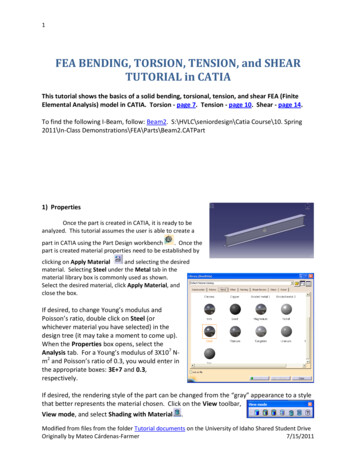
1FEA BENDING, TORSION, TENSION, and SHEARTUTORIAL in CATIAThis tutorial shows the basics of a solid bending, torsional, tension, and shear FEA (FiniteElemental Analysis) model in CATIA. Torsion - page 7. Tension - page 10. Shear - page 14.To find the following I-Beam, follow: Beam2. S:\HVLC\seniordesign\Catia Course\10. Spring2011\In-Class Demonstrations\FEA\Parts\Beam2.CATPart1) PropertiesOnce the part is created in CATIA, it is ready to beanalyzed. This tutorial assumes the user is able to create apart in CATIA using the Part Design workbench. Once thepart is created material properties need to be established byclicking on Apply Materialand selecting the desiredmaterial. Selecting Steel under the Metal tab in thematerial library box is commonly used as shown.Select the desired material, click Apply Material, andclose the box.If desired, to change Young’s modulus andPoisson’s ratio, double click on Steel (orwhichever material you have selected) in thedesign tree (it may take a moment to come up).When the Properties box opens, select theAnalysis tab. For a Young’s modulus of 3X10⁷ Nm2 and Poisson’s ratio of 0.3, you would enter inthe appropriate boxes: 3E 7 and 0.3,respectively.If desired, the rendering style of the part can be changed from the “gray” appearance to a stylethat better represents the material chosen. Click on the View toolbar,View mode, and select Shading with Material.Modified from files from the folder Tutorial documents on the University of Idaho Shared Student DriveOriginally by Mateo Cárdenas-Farmer7/15/2011
22) Analysis CaseTo begin the analysis on the part, select Start Analysis & Simulation GenerativeStructural Analysisworkbench. When the New Analysis Case box appears, keep the StaticAnalysis selection and press OK.Now specify the “size” and “sag”. “Size” simply refers to theelemental size of the mesh seen on the part; and “sag” refers tothe internal distance between the mesh size and the actualgeometry of the part. “Sag” is unique to CATIA, and this tutorialdoes not go into depth.There are two ways to change “size” and “sag”. The first is tosimply double click on their respective icons in the screen asshown.The second method is to double click on the branch OCTREETetrahedron Mesh in the design tree. Both methods willopen up the OCTREE Tetrahedron Mesh box. Set Size and Sagand make sure Absolutesag is checked, whichkeeps the icon in thescreen. You do notnecessarily want Size to betoo small.SagSizeTo view the mesh, right click on Nodes and Elements inthe design tree and click Mesh Visualization. A warningmay appear about recalculating; click OK. The mesh isnow displayed on the part. It may be helpful to selectShading with Edgesfrom the View mode tool bar to better see how the mesh is shaped.3) RestraintsTo unhide the part, right click Links Manager.1 in the design tree and select Hide/Showto show both the mesh and the part superimposed on each other. It should appear similar tothe below image; this will allow you to go ahead and select the surfaces/faces desired you wantrestrained. If you wish to hide the mesh only, in the design tree right click Nodes and Elementsand select Hide/Show. Both the mesh and the part are still activated, but this hides the mesh.If desired, you can also Activate/Deactivate the mesh by right clicking Mesh under Nodes andElements in the design tree. Applying restraints to the part is done through the RestraintsModified from files from the folder Tutorial documents on the University of Idaho Shared Student DriveOriginally by Mateo Cárdenas-Farmer7/15/2011
3toolbar. For this partwe are going to restrain one end usingthe Clamp restraint. Be carefulto select only the bottom face and notany of the edges.4) LoadingTo apply a bending load to the above part, the Loadstoolbaris utilized. Forthe purposes of this tutorial, a distributed load, orforce, will be applied to the other end of the part.Select Distributed Forceand a box of the samename appears. For Supports select the entire backface. Again, like in Restraints, if you are unable toselect the face, right click Links Manager.1 in theDesign tree and select Hide/Show. This will allow you to select theface(s)/edge(s) desired. Then, to apply a 2000 N force to the end,enter 2000 N in the Norm box, then Tab down to the X directionbelow it, enter “0”, then Tab down into the next text box Y and enter2000 N, and finally Tab into the Z; this allows the loads to take effect.Click OK. The negative sign in the Y-direction simply points the forcein the negative Y-direction, as shown. Of course, the forces anddirections are up to the user’s decision depending on the particularproject.The FEA analysis now needs to be performed. Click Computewhich opens the Compute box, leave the selection at All, and click OK.NOTE: It may be necessary to use the Compute command afteropening the analysis project again in order to perform the Postprocessing functions mentioned later in the tutorial.CATIA then brings up theComputation Resources Estimationwhich shows the resources used tocomplete the analysis. Click Yes tocontinue the computation.Modified from files from the folder Tutorial documents on the University of Idaho Shared Student DriveOriginally by Mateo Cárdenas-Farmer7/15/2011
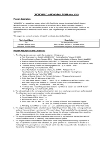
45) Post processingTo view the various post processing features, such as: Deformation, Scaling, von Misesstresses, and Displacement, use the Image toolbarshape, click Deformation. For example, to deform theand the following appears:However, this displacement is scaled and not a true representation of the actual deformedshape. The scale can be changed using the Amplification Magnitude iconAnalysis Tools toolbar.Amplification Magnitude box appears.Click thelocated in thebutton and theEither the Scaling factor or the Maximum amplitude can beadjusted. The default scaling factor for this analysis is 3.4646 andthe coinciding maximum amplitude, or deflection length, is 73.421mm. The bar can be manually adjusted, or a value can be inputtedfor the desired scaling factor or maximum amplitude.Modified from files from the folder Tutorial documents on the University of Idaho Shared Student DriveOriginally by Mateo Cárdenas-Farmer7/15/2011
5From the Imagetoolbarselectthe Displacementcommandwhich shows adisplacementvector field.Double click on oneof the arrows tobring up the Image Edition box, select Average iso, andclick OK.The image below is still in the Shading with Matieralview mode. The view Shading with edgesmesh.shows theSelect the View ModeCustomization button, whichopens a box of the same name, andcheck everything shown to the left.The result is shown on the next page.Modified from files from the folder Tutorial documents on the University of Idaho Shared Student DriveOriginally by Mateo Cárdenas-Farmer7/15/2011
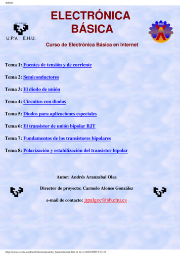
6To view the von Mises stress, click the von Mises Stresscommand that will display therespective stresses shown below.To view animations of the deflections or stresses, cut planes, maximum/minimums, or thefeatures use the Analysis Toolstoolbar.Modified from files from the folder Tutorial documents on the University of Idaho Shared Student DriveOriginally by Mateo Cárdenas-Farmer7/15/2011
7FEA TORSION TUTORIAL in CATIAThe following tutorial shows how to attach a torsion moment onto a part, assumingknowledge from previous tutorials.If I-Beam is no longer open, follow: Beam2. S:\HVLC\seniordesign\Catia Course\10. Spring2011\In-Class Demonstrations\FEA\Parts\Beam2.CATPart1) New Static CaseStart out byadding a new StaticCase if the part isalready in thedrawing area. Thisallows a new loadto be added to thepart. Select StaticCase under Insertin the Main menu.There are othercases, but this tutorial onlyshows the static case.Once the Static Case boxappears, select OK and youwill notice that the designtree expands with anotherStatic Case.2) RestraintsAdd Restraintsas before in the bending tutorial. The User-definedRestraint buttonmay be used to select where restraints are desired on the part.Once selected, a box of the same name appears that shows Translation and Rotation restraints.The end face of the I-Beam were selected here, however any other face or edge may beselected. Again, make sure the part resembled that shown by right clicking in Links Manager.1is selecting Hide/Show.Modified from files from the folder Tutorial documents on the University of Idaho Shared Student DriveOriginally by Mateo Cárdenas-Farmer7/15/2011
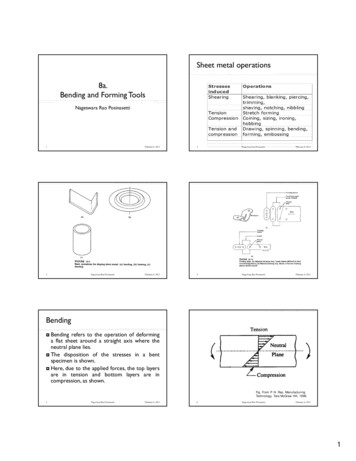
83) LoadingIn the Loads toolbarselect the Moment command. When the box appears,specify a moment. Similar for bending select the face onlyfor Supports. The units are force X length. To apply atorsion load to the beam with its current orientation, themoment has to be applied about the X-axis. To input amoment of 1500 N-m, input 1500Nxm in Norm, Tab down toX, input -1500Nxm, and then Tab into the Y-direction. Thisallows the moment to take effect. Click OK.You may need to check mesh and sag if not continuedfrom bending example.Click Computeas before. A message may appearconcerning restraining the part further; you may click OK.Select Deformationfrom the Imagetoolbar to see how the beam twists.Modified from files from the folder Tutorial documents on the University of Idaho Shared Student DriveOriginally by Mateo Cárdenas-Farmer7/15/2011
94) Post ProcessingThe other analyses from the Image toolbar may be appliedas before.Modified from files from the folder Tutorial documents on the University of Idaho Shared Student DriveOriginally by Mateo Cárdenas-Farmer7/15/2011
10FEA TENSION TUTORIAL in CATIAThe following tutorial shows how to set up tension due to displacement onto a part,assuming knowledge from previous tutorials.1) Setting Up: Open file Shaft-tensile. S:\HVLC\seniordesign\Catia Course\10.Spring 2011\In-Class Demonstrations\FEA\Parts\Shafttensile.CATPart Open the Generative Structural Analysis workbench. SelectStart Analysis & Simulation Generative StructuralAnalysis. A Warning Window will pop up saying that the material is notdefined. Select ok.Select static case from the pop up windowSelect the apply material icon. Select the metal tab and thenselect steel. Click on the part in the view window and selectapply.Select the customized view modeand make sure the meshshading and material are both selected.2) Mesh creation: Enable mesh visualization. Rightclink on Nodes and Elements inthe design tree and then selectmesh visualization. A warningwill pop up saying that the meshneeds to be updated. Select ok. If the mesh is not an appropriatesize, you can modify it. ExpandNodes and Elements under thedesign tree and double clink onthe OCTREE Tetrahedron Mesh.1.Input the values of the size andthe sag as shownbelow. And select ok.Notice that the greenand blue symbols onthe part also change.The green symbolrepresents the size ofeach element and theblue symbol representsthe sag.Modified from files from the folder Tutorial documents on the University of Idaho Shared Student DriveOriginally by Mateo Cárdenas-Farmer7/15/2011
11 Notice also that the mesh disappears. Right clink onNodes and Elements and select mesh visualization againto update the mesh. Smaller meshes give more accurateresults but take longer to process.Now deactivate the created mesh. Right clink on Mesh.1under Nodes and Elements in the design tree and selectActivate/Deactivate. This will hide the mesh so restraintscan be applied.3) Apply Restraints: Select surface sliderand select the three faces asshown. This prevents the faces from moving in theirtangential directions. Now the part is fully restrained.Notice how the surface sliders have been added to thedesign tree under restrains in the static case.Modified from files from the folder Tutorial documents on the University of Idaho Shared Student DriveOriginally by Mateo Cárdenas-Farmer7/15/2011
124) Apply loads: To apply an enforced displacement, a restraint must first be applied. Select UserDefined Restraintshown. . And select the end face as shown. Select restrain translation 1 asNext select enforced displacement. Select the restraint that was just created eitherin the design tree or in the design window. Then enter the desired displacement of .2inas shown and select OK.Modified from files from the folder Tutorial documents on the University of Idaho Shared Student DriveOriginally by Mateo Cárdenas-Farmer7/15/2011
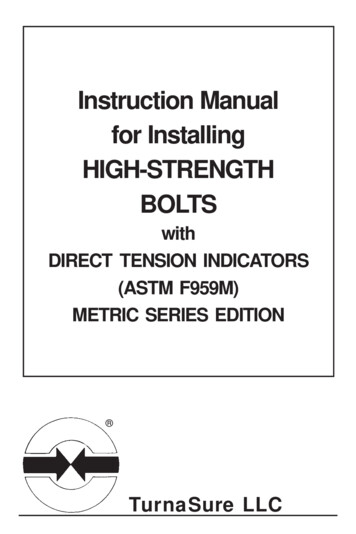
135) Compute solution: Select Compute. A pop up box appears asking what you would like to compute.Make sure “all” is selected and then hit OK. If a warning dialogue box appears, select ok.A computation resource box then appears. Select yes and the computation will begin.6) View Results: Select displacement Select Von Misses Stress Each of these analysis views are stored in the static case solution tab in the design tree.To select which one(s) are viewable right clink on them in the design tree and selectactivate/deactivate.Note that there are multiple ways to go about getting a similar solution.Modified from files from the folder Tutorial documents on the University of Idaho Shared Student DriveOriginally by Mateo Cárdenas-Farmer7/15/2011
14FEA SHEAR TUTORIAL in CATIAThe following tutorial shows how to set up shear analysis for a part, assuming knowledgefrom previous tutorials.7) Setting Up: Open file Shear. S:\HVLC\seniordesign\Catia Course\10.Spring duct Open the Generative Structural Analysis workbench. Selectstart-Analysis and Simulation-Generative StructuralAnalysis. Select static case from the pop up window On the design tree, you will see two icons under the Analysis Manager. The first one isthe Links Manager. This links the Analysis to the specifiedpart(s) or product(s). You will notice that the part hasautomatically been added to the links manager. the material has already been applied to the parts Select the customized view modeand make sure the meshshading and material are both selected.8) Mesh creation: Enable mesh visualization. Right clink on Nodes and Elements inthe design tree and then select mesh visualization. A warningwill pop up saying that the mesh needs to be updated. Selectok. If the mesh is not an appropriate size, you can modify it. ExpandNodes and Elements under the design tree and double clink oneach OCTREETetrahedron Mesh.Input the values of thesize and the sag asshown below to eachmesh and select ok.Notice that the greenand blue symbols onthe part also change.The green symbolrepresents the size ofeach element and theblue symbol representsthe sag. Notice also that themesh disappears. RightModified from files from the folder Tutorial documents on the University of Idaho Shared Student DriveOriginally by Mateo Cárdenas-Farmer7/15/2011
15clink on Nodes and Elements and select mesh visualization again to update the mesh.Smaller meshes give more accurate results but take longer to process. Now deactivate the created mesh. Right clink on Mesh.1 under Nodes and Elements inthe design tree and select Activate/Deactivate. This will hide the mesh so restraints canbe applied.9) Create analysis supports: The supports for this assembly havebeen created in the AssemblyWorkbench. They are simply therestraints. They can be seen byexpanding the links manger in thedesign tree to the contraints and canalso been seen in the design window.For demonstration purposes we willadd one Analysis Support. Thissupport will constrain the contactingfaces of parts A and B. Select the general AnalysisConnection icon. For the firstcomponent and second components,select the contacting faces as shown. Select okModified from files from the folder Tutorial documents on the University of Idaho Shared Student DriveOriginally by Mateo Cárdenas-Farmer7/15/2011
1610) Define connection Properties: Now properties need to be added to the connections which restrain parts A and B tothe pin. Select Contact Connectionfrom the connection properties toolbar. Now expandLinks Manager in the design tree so that the constraints are visible. Select A-pin:1 forthe support and select the friction ratio box. This will restrain the pin from moving in theX direction. Select OK. Repeat the previous step for the two remaining constraints A-pin:2 and B-pin.Now connection properties will be added to constrain the wall contacts of part A and B.One of these connections was made in the Assembly Workbench using a contactrestraint and the other is the one which was previously created. Select Contact Connectionand select A-B:1 in the design tree as shown. A-B:1 is acontact constraint between the walls of parts A and B. Select ok. Select Contact Connection again and now select either the red line in the design windowwhich represents the Analysis connection we previously made or select it in the designtree as shown and select ok.NOTE: FOR MORE INFORMATION ON ASSEMBLY CONNECTIONS GO HERE. T:\CatiaCourse\10. Spring 2011\In-Class Demonstrations\FEA\TUTORIAL 2\FEA AssembliesConnectionsModified from files from the folder Tutorial documents on the University of Idaho Shared Student DriveOriginally by Mateo Cárdenas-Farmer7/15/2011
1711) Apply Restraints: Select clampfrom the restraintstoolbar and select the bottom face ofpart B as shown.12) Apply loads: Select distributed forceand selectthe top face as shown. Enter a value of2000N in the Z direction.13) Compute solution: Select Compute. A pop up boxappears asking what you would like tocompute. Make sure “all” is selectedand then hit OK. If a warning dialoguebox appears, select ok. A computationresource box then appears. Select yesand the computation will begin.If an error box appears as shown. Itusually means that the model is notfully retrained. Select ok and thenModified from files from the folder Tutorial documents on the University of Idaho Shared Student DriveOriginally by Mateo Cárdenas-Farmer7/15/2011
18select the displacement iconto diagnose what is wrong withyour model.14) View Results: Select displacement Select Von Misses Stress.Modified from files from the folder Tutorial documents on the University of Idaho Shared Student DriveOriginally by Mateo Cárdenas-Farmer7/15/2011
TUTORIAL in CATIA This tutorial shows the basics of a solid bending, torsional, tension, and shear FEA (Finite Elemental Analysis) model in CATIA. Torsion - page 7. Tension - page 10. Shear - page 14. To find the following I-Beam, follow: Beam2. S:\HVLC\seniordesign\Catia Course\10. Sp