Transcription
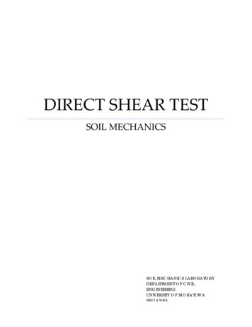
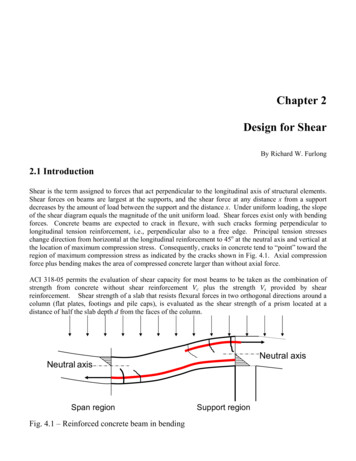
Chapter 2Design for ShearBy Richard W. Furlong2.1 IntroductionShear is the term assigned to forces that act perpendicular to the longitudinal axis of structural elements.Shear forces on beams are largest at the supports, and the shear force at any distance x from a supportdecreases by the amount of load between the support and the distance x. Under uniform loading, the slopeof the shear diagram equals the magnitude of the unit uniform load. Shear forces exist only with bendingforces. Concrete beams are expected to crack in flexure, with such cracks forming perpendicular tolongitudinal tension reinforcement, i.e., perpendicular also to a free edge. Principal tension stresseschange direction from horizontal at the longitudinal reinforcement to 45o at the neutral axis and vertical atthe location of maximum compression stress. Consequently, cracks in concrete tend to “point” toward theregion of maximum compression stress as indicated by the cracks shown in Fig. 4.1. Axial compressionforce plus bending makes the area of compressed concrete larger than without axial force.ACI 318-05 permits the evaluation of shear capacity for most beams to be taken as the combination ofstrength from concrete without shear reinforcement Vc plus the strength Vs provided by shearreinforcement. Shear strength of a slab that resists flexural forces in two orthogonal directions around acolumn (flat plates, footings and pile caps), is evaluated as the shear strength of a prism located at adistance of half the slab depth d from the faces of the column.Neutral axisNeutral axisSpan regionFig. 4.1 – Reinforced concrete beam in bendingSupport region
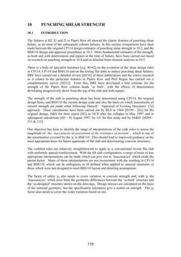
2.2 Shear strength of beamsEquation (11-3) of ACI 318-05, Section 11.3.1.1 permits the shear strength Vc of a beam without shearreinforcement to be taken as the product of an index limit stress of 2 fc’ times a nominal area bwd. Withfc’ expressed in lb/in2 units and beam dimensions in inches, nominal shear strength Vc 2 fc’bwd in unitsof lb. Shear reinforcement is not required for slabs, which can be considered as very wide beams. If thewidth of a beam is more than twice the thickness h of the beam, ACI 318-05, Section 11.5.6.1(c) exemptssuch beams from the requirement of shear reinforcement as long as the shear capacity of the concrete isgreater than the required shear force. A more complex method for determining Vc is given in ACI 318-05,Section 11.3.2.1. The method is demonstrated in SHEAR EXAMPLE 2. A special type of ribbed floorslab known as a joist system can be constructed without any shear reinforcement in the joist ribs. Joistsystem relative dimensions, slab thickness, rib width and spacing between ribs are specified in ACI 31805, Section 8.11.A diagonal crack that might result in shear failure, as suggested in Fig.2.2, can form no closer to the faceof the support than the distance d from the face of the support. Consequently, Section 11.1.3.1 of ACI318-05 permits the maximum required value of shear Vu to be determined at a distance d from the face ofsuch a support when the support provides compression resistance at the face of the beam opposite theloading face. If loads had been suspended from the bottom of the beam, or if the support were no deeperthan the beam itself, maximum required shear must be taken as the shear at the face of the support.The most common form of shear reinforcement is composed of a set of bars bent into U-shaped stirrups asindicated by the vertical bars in Fig. 2.2. The stirrups act as tension hangers with concrete performing ascompression struts.Shear Reinforcement for Beams45o Shear cracks are pinnedVc ddtogether by stirrups.Vs Avfyd/ss s s sStandard U-stirruphas 2 legs.Av 2 AbarFig. 2.2 – Shear reinforcementEach vertical leg of a stirrup has a tension capacity equal to its yield strength, and the most commonstirrup has 2 vertical legs. The shear capacity of vertical stirrups is the tension strength of one stirruptimes the number of stirrups that interrupt potential cracks on a 45-degree angle from the tension steel.Thus, Vs Avfyd/s. A U-stirrup has an area Av 2(area of one stirrup leg). Shear capacity at any locationalong a beam Vn Vc plus Vs.
2.3 Designing stirrup reinforcement for beamsShear reinforcement Av must provide the strength required in addition to the strength of concrete Vc.Thus, the required amount of Av (Vn – Vc)/(fytd/s). The strength reduction factor φ for shear is 0.75. φVnmust be greater than Vu. When the quantities Av, fy and d are known, stirrup spacing s can be computed ass (φAvfytd) / (Vu - φVc)(2.1)ACI 318, Section 11.5.6.1 requires the placement of shear reinforcement in all beams for which therequired strength is more than half the value of φVc. The full development of a critical shear crackbetween stirrups is prevented by ACI 318-05, Section 11.5.5, which sets the maximum spacing of stirrupsat d/2 when Vu 6φVc, but maximum spacing is d/4 when Vu 6φVc. Concrete cannot act effectively ascompression struts if the required amount of Vs exceeds 8Vc 8bwd fc’ regardless of shear reinforcement.Thus, a beam section must be made larger if Vn 10bwd fc’.A graph given in design aid SHEAR 1 displays limits of nominal shear stress values of Vn/(bwd) forconcrete strength fc’ from 3000 psi to 10,000 psi. The graph is not intended for precise evaluation ofmember capacity, as precise strength values are given in other design aids. Rather, the graphs clearlyshow stress ranges for which design requirements change. No shear reinforcement (stirrups) are requiredif Vn/(bwd) is less than 1.0 fc’. The capacity Vc of concrete in sections reinforced for shear is 2.0bwd fc’.The strength of stirrups can be added to the concrete strength Vc to determine the total strength of asection. Required stirrups must be spaced no more than d/2 apart where Vn/(bwd) 6.0 fc’. WhereVn/(bwd) 6.0 fc’, maximum stirrup spacing becomes d/4. The compressive strut capacity of concrete isreached if Vn/(bwd) 10.0 fc’. Additional stirrups cannot increase section shear strength, as the concretestrength is considered exhausted when Vn/(bwd) 10 fc’.Design aid SHEAR 2 consists of 3 tables that may be used to determine shear capacity for rectangularsections of width b or bw from 10 in to 32 in and thickness h from 10 in to 48 in. It is assumed that depthd is 2.5 inches less than thickness for h 30 in, but that larger longitudinal bars would make d h – 3 infor deeper beams.Table 2a gives values Kfc (fc’/4000) to be used as modifiers of Kvc when members are madewith concrete strength different from fc’ 4000 psi. In conjunction with required stirrups, the nominalshear strength of concrete Vc KfcKvc.Table 2b contains values Kvs for determining nominal stirrup capacity Vs Kvs(Av/s).Table 2c gives values Kvc in kips. Kvc is the shear strength of concrete when required stirrupsareused in members made with fc’ 4000 psi concrete.The nominal strength of a rectangular section is the sum of concrete strength Vc and reinforcementstrength Vs to give Vn KfcKvc Kvs(Av/s).SHEAR 3 is a design aid for use if Grade 60 stirrups larger than #5 are to be used, and sections must bedeep enough for tension strength bar development of larger stirrups or closed ties. Required thickness ofsection values are tabulated for concrete strengths from 3000 psi to 10,000 psi and for #6, #7 and #8stirrups. It should be noted that ACI 318–05, Section 11.5.2 limits the yield strength of reinforcing barstirrups to no more than 60,000 psi.ACI 318-05, Section 11.5.6.3 sets lower limits on the amount of shear reinforcement used when suchreinforcement is required for strength. These limits are intended to prevent stirrups from yielding upon3
the formation of a shear crack. The limit amount of Av must exceed 50bws/fy 0.75 fc’bws/fy. The secondquantity governs when fc’ is greater than 4444 lb/in2.The design of shear reinforcement includes the selection of stirrup size and the spacing of stirrups alongthe beam. Design aids SHEAR 4.1 and SHEAR 4.2 give strength values Vs of #3 U stirrups and #4 Ustirrups (two vertical legs) as shear reinforcement tabulated for depth values d from 8 in to 40 in andstirrup spacing s from 2 in to maximum permitted spacing s d/2. Each table also lists the maximumsection width for which each stirrup size may be used without violating the required minimum amount ofshear reinforcement. SHEAR 4.1 applies for Grade 40 stirrups, and SHEAR 4.2 applies for Grade 60stirrups.2.4 Shear strength of two-way slabsLoads applied to a relatively small area of slabs create shear stress perpendicular to the edge(s) of the areaof load application. Columns that support flat plate slabs and columns that are supported by footings arethe most common examples. ACI 318-05, Section 11.12.2.1 provides expressions for determining shearstrength in such conditions for which shear failure is assumed to occur near the face(s) of the columns.Failure is assumed to occur on the face(s) of a prism located at a distance of d/2 from each column face.The perimeter bo of the prism multiplied by the slab depth d is taken as the area of the failure surface.Three expressions are given for computing a critical stress on the failure surface. A coefficient αs 40for interior columns, αs 30 for edge columns and αs 20 for corner columns is used to accommodatecolumns located along the perimeter of slabs. The critical (failure) stress may be taken as the least valueof either 4 fc‘ , (2 4/β) fc‘ , or (αsd/bo 2) fc‘. The quantity β is the ratio of long side to short side ofthe column. The first expression governs for centrally loaded footings and for interior columns unless theratio β exceeds 2 or the quantity 40d/bo is less than 2. Shear strength at edge columns and corner columnsthat support flat plates must be adequate not only for the direct force at the column but also for additionalshear forces associated with moment transfer at such columns.Diagrams for the prism at slab sections for columns are shown with SHEAR EXAMPLES 5, 7 and 8.Design aid SHEAR 5.1 gives shear strength values of two-way slabs at columns as limited by potentialfailure around the column perimeter.Table 5.1a gives values of K1 as a function of slab d and column size b and h.Table 5.1b gives values of the shear stress factor K2 as a function of the ratio βc between thelonger side and the shorter side of rectangular column sections.Table 5.1c gives values of nominal strength Vc as a function of the product K1K2 and the nominalcompressive strength of slab concrete fc’.Design aid SHEAR 5.2 is similar to SHEAR 5.1 for determining slab shear capacity at round columns.For circular columns, there is no influence of an aspect ratio as for rectangular columns, and the designaid is less complex.Table 5.2a gives, for slab d and column diameter h, values of a shape parameter K3 in sq in units.Table 5.2b gives, for K3 and slab concrete fc’, the value of nominal shear capacity Vc in kip units.4
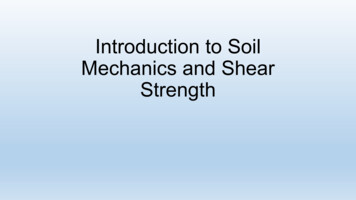
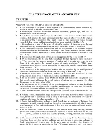
2.5 Shear strength with torsion plus flexural shearTorsion or twisting of a beam creates shear stress that is greatest at the perimeter of sections. The shearstress due to torsion adds to flexural shear stress on one vertical face, but it subtracts from flexural shearon the opposite vertical face. Shear stress due to torsion is negligibly small near the center of sections.ACI 318-05, Section 11.6 provides empirical expressions for torsion strength. It is assumed thatsignificant torsion stress occurs only around the perimeter of sections, and no torsion resistance isattributed to concrete. The definitions of section properties are displayed in Fig. 2.3.DefinitionsAcp area enclosed by outside perimeter ofsection.Ao gross area enclosed by shear flow path.Aoh area enclosed by centerline of closed tie.pcp outside perimeter of concrete section.ph perimeter of centerline of closed tie.bw1¾ inFlexural shear Torsional shearh 1¾ inAohAcppcp1¾ inpcpphAcp bwhpcp 2(bw h)Aoh (h-3.5)(bw-3.5)ph 2[(b-3.5) (h-3.5)]Ao 0.85AohAcp1¾ inMultiple rectanglesFig. 2.3 – Torsion strength definitions of section propertiesConcrete beams properly reinforced for torsion display considerable ductility, continuing to twist withoutfailure after reinforcement yields. Consequently, ACI 318-05, Section 11.6.2.2 permits design for torsionin indeterminate beams to be made for the torsion force that causes cracking. A member is determinate iftorsion forces can be determined from the equations of statics without considering compatibilityrelationships in the structural analysis. A member is indeterminate if torsion forces must be estimatedwith consideration of compatibility conditions, i.e., there exists more than one load path for resistingtorsion. The illustrations in Fig. 2.4 show two conditions of a spandrel beam supporting a brick ledge.The determinate beam in the upper sketch must transfer to columns allof the eccentric load on the ledgeonly through the twisting resistance (torsion) of the beam. In contrast, the indeterminate beam in thelower sketch supports a slab that extends outward to receive the eccentric load on the ledge. Theeccentric load can be transferred to columns both by torsion of the beam and by flexure of thecantilevered slab.5
DETERMINATE TORSIONEccentricity eLoad w/ft nTorque -w e/2Torquew e/2Eccentricity eLoad w/ftINDETERMINATE TORSIONFig. 2,4 – Determinate torsion versus Indeterminate torsionCracking torque Tcr is to be computed without consideration of torsion reinforcement.Tcr 4 fc’(Acp)2 / pcp(2.2)Torques smaller than one-quarter of the cracking torque Tcr will not cause any structurally significantreduction in either the flexural or shear strength and can be ignored. An upper limit to the torqueresistance of concrete functioning as compression struts is taken from ACI 318-05, Eq. (11-18) as:Tmax 17(Aoh)2 fc’ / ph .(2.3)Torsion reinforcement requires both closed ties and longitudinal bars that are located in the periphery ofthe section
ACI 318-05 permits the evaluation of shear capacity for most beams to be taken as the combination of strength from concrete without shear reinforcement Vc plus the strength Vs provided by shear reinforcement. Shear strength of a slab that resists flexural forces in two orthogonal directions around a column (flat plates, footings and pile caps), is evaluated as the shear strength of a prism .