Transcription
Introduction to SoilMechanics and ShearStrength
Learning Objectives Understand different soil types. Understand the basics of soil shear strength. Understand what conditions dictate the type of shear strengththat should be considered.
Definition Soil – an un-cemented aggregate of rock and mineral grainsand decaying organic matter (solid particles) with liquid and/orgas occupying the void space between the solid particles.3
Properties of Solid Particles Particle sizeSmallLargeClay -- Silt -- Sand -- Gravel -- Cobbles -- Boulders 0.075mm 4.75 mm 75mm350mmA quantitative measure of soil particles. Particle shapeRounded -- Subrounded -- Subangular -- AngularA qualitative measure of soil particles.4
Engineering Soil Classification The purpose: Common language for naming soils. Mixtures of particles that vary in mineralogyand particle size. Categorize soils based on their engineeringproperties and characteristics. Based partly on grain size. Based partly on index properties.5
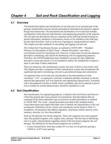
Silts and Clays Particles smaller than we can detect by visual or sieveanalysis methods. Silts are very fine bulky particles like sands – they arerock and mineral fragments – they are reasonably inert. Clays are minerals that are the product of chemicalweathering of feldspar, ferromagnesian, and micaminerals. Clay particles are very small and are chemically active. Silts and Clays exhibit different engineering behavior.6
7
The Plasticity Chart8
How do we determine shear strength ofsoil and rock? Direct Shear Triaxial Shear In-situ testing (Vane Shear, CPT, SPT correlations, SchmidtHammer) Correlations Back-analysis of existing landslide geometry.
Most Important Concept: Effective Stress Effective Stress is arguably the most important concept in soilmechanics. It dictates the relationship between water pressure and the mobilizedstress in a soil matrix. Most simply, it is defined as:Effective Stress Total Stress – Pore Water Pressure𝝈𝝈′ 𝝈𝝈 𝒖𝒖 Effective Stress Actual Contact Forces between Soil Grains Total Stress The total weight of soil and water within a column. Pore Water Pressure The buoyant forces pushing grains apart.
Concept of Effective Stress Let’s take an example that we all remember from childhood: airhockey. When the air is off, the puck doesn’t slide as well. The reaction force, N, is equal to the weight of the puck. Friction is N multiplied by a friction coefficient.Weight, WF, FrictionN, Normal Reaction Force
Concept of Effective Stress If we turn on air on the table, the reaction force is no longerequal to the weight. The normal decreases the by uplift force from air. Thus, friction decreases and the puck slides easily. This is conceptually the same as “buoyancy.”Weight, WF, FrictionU, Uplift from AirN, Normal Reaction ForceU, Uplift from Air
Shear Strength of CoarseGrained Materials
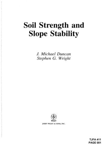
a m p le H e ig hS h e a r L oShear Strength of Cohesionless MaterialsDirect Shear Tests on Dry SandDense SandLoose SandSShear Displacement,S
Effect of Normal StressShear StressNormal Stresscmaxb maxa maxShear Displacement,c bb aa
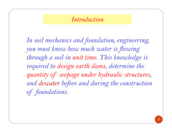
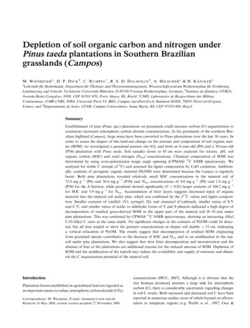
Shear stress[Shear strength for the plotted points]Plot of shear strength versus normal stressScSbEnvelope ofFailure Stress CombinationsEffectiveFrictionAngle'Zone of impossiblestress combinations[i.e. failure]Zone of possible stress combinationsSaabNormal Stressc[Also Effective Normal Stress since there is no water]16
We can represent the strength as related toeffective normal stress.Shear StrengthEffectiveFrictionAngleMohr-Coulomb Strength EquationS ' tan 'Effective Normal Stress′'′𝑆𝑆 𝜎𝜎 tan(𝜙𝜙 )'17
Shear Strength of FineGrained Materials
Similarities to Coarse-Grained Materials Shear strength is a function of effective stress. Shear strength is defined by the MohrCoulomb strength equation in terms ofeffective stress. In some cases the Mohr-Coulomb failureenvelope [the line defined by the equation]passes through the origin.19
Differences In some cases the Mohr-Coulomb failureenvelope will have a shear stress intercept -- itwon’t pass through the origin. It is important to account for how pore waterpressures change with time.20
Pore pressure and drainage response of soilsClay SoilsPore PressureuexcessClays have very highexcess pore pressureNote: excess pore pressures can be negativeas well as positive.Clays and Sands havethe same pore pressureSandsuoSands have nearly zeroexcess pore pressureTimeConstruction Period[Period of Change in Total Stress]21
Total StressIf we put the pore pressure behavior together witheffective stress, we get:oTotal Stress Change from Construction[e.g. placement of a fill, excavation of a slope]Effective StressPore PressureTimeu f(consolidation process)uoKnown Effective Stresso'TimeEffective Stress f(u)But there is a problem!Time22
Drained versus Undrained Behavior Look only at the extreme cases. The “long term” or equilibrium case is thesame as sand – the pore pressures are equalto the ambient values which are a function ofthe ground water table. This is called theDrained Case. The case immediately following loading, istermed the Undrained Case since little of thepore pressure generated in response to theTotal Stress change would have disappeared.23
The Undrained and Drained Strength States-- illustrated in terms of pore pressure.Undrained casePore Pressureu excess[before pore pressures have dissipated]Clay SoilsNote: excess pore pressures can be negativeas well as positive.uoDrained Case[pore pressures in equilibrium]TimeConstruction Period[Period of Change in Total Stress]24
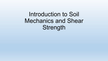
S h e a r S tre sUndrained Shear Strength of Fine-grained Soils.Line tangent to circles has zero slope.Hence this is often referred to as theO 0 caseNormal StressRange in Cell Pressures𝑆𝑆 𝑐𝑐𝑢𝑢25
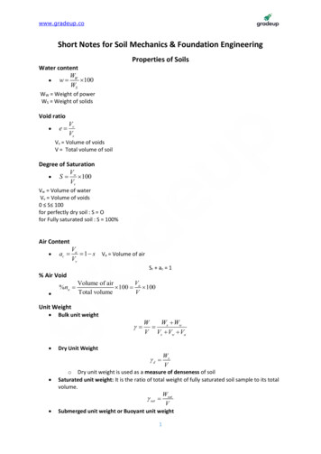
Shear StressTypical drained shear strength for loosely-deposited fine-grained soil.Mohr-Coulomb Envelope[line tangent to failure circles]( 3 )a ( 3 )b′′𝑆𝑆 𝜎𝜎 tan(𝜙𝜙 )( 3 )c ( 1 )aEffectiveFrictionAngle'( 1 )b( 1 )cEffective Normal Stress26
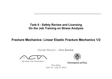
Shear StressTypical drained shear strength for overconsolidated fine-grained soils orcemented soils.EffectiveStrengthenvelope c'intercept′′FrictionAngleMohr-Coulomb Envelope[line tangent to failure circles]( 3)a ( 3)b′𝑆𝑆 𝑐𝑐 𝜎𝜎 tan(𝜙𝜙 )( 3)c ( 1)a'( 1)b( 1)cEffective Normal Stress27
Total Stress, Effective Stress and ShearStrength Parameters Drained field conditions critical: Use effective stressanalysis drained shear strength parameters Undrained field conditions critical: Use total stressanalysis undrained shear strength parameters If in doubt, analyze twice each time using consistentshear strength parameters
Total Stress vs. Effective Stress inStability Analysis Total stress analysis: Only total soil stresses are used PWP is not considered Fast loading (construction, traffic, seismic) Effective stress analysis: Only effective soil stresses are used PWP must be considered Slow loading (rainfall, slow changes, afterconstruction)
Conceptual Process in Stability Analysis1. Consider loading versus time2. Consider PWP versus time3. Consider shear resistance versus time4. Assess the available resistance over driving loadversus time establish critical situation5. Conclude with the type of stress and strengthparameters to use in stability analysis
Justify theseconclusions:EmbankmentClayey foundation1. End ofconstructionis criticalHeight of Fillτ at PPWPat PTimeFOS3. Use undrained shearstrengthparameters(φu 0)τStrengthat P2. Total stressanalysis isappropriatePTimePWP DissipationRapidConstructionPWP Equilibrium
Justify theseconclusions:3. Drained shearstrengthparameters(φ’ and c’)τ at PPWP at PHeight Above PFOS2. Effective stressanalysis isappropriateP Clayey cut slopeInitial GWTTimeFinal GWTStrengthat P1. Long-termstability iscriticalGWTφu 0φ’, c’PWP RedistributionRapidExcavationTimePWP at Equilibrium
SummaryAspectEnd StrengthFree Drainingσ’, φ’, c’σ’, φ’, c’σ’, φ’, c’Analysis/StrengthImpermeableσ, (φu 0, cu)or (φ, c) UU, CUσ, (φu 0, cu) CUσ’, φ’, c’Pore WaterPressureu 0 totalu 0 effectiveu 0 totalu 0 effectiveu 0 effective
The Residual State When soil has sheared significantly (i.e. active landslide terrain), the grainsalign and cemented bonds are broken. Often, the cementation is what provides “cohesion” – this disappears. When the grains align, significantly less friction is mobilized. This occurs well-past peak shear strength Skempton (1970)
Why it matters. Active landslide on Oregon Coast (Schulz et al. 2007). Shear strength properties of undisturbed, cemented material: Cohesion: 2340 psf Friction: 26.7 Residual State: Cohesion: 0 psf Friction: 15.8
Cohesion – is it real? It depends. When unsure, neglect it in the drained, long-termcase. What might seem like cohesion, but is not: Soil suction from not being saturated. Unloading of dense material. Shearing of dense grains. What is actually cohesion: Cemented grains.When in doubt, c’ 0!
Rock Shear Strength Conventionally, Hoek-Brown Model isused for assessing the shear strength ofrock. Developed initially for tunnelingapplications, used for assessment ofrockslope stability and foundations now. Big difference is the incorporation oftensile strength andfracturing/competence of geomaterials. Can be determined from uniaxialcompressive testing of rock cores.
Hoek-Brown Failure Criteria Typical Hoek-Brown failure envelope defined as:𝜎𝜎3 ′𝜎𝜎1 ′ 𝜎𝜎3 𝜎𝜎𝑐𝑐𝑐𝑐 ′ 𝑚𝑚 𝑠𝑠𝜎𝜎𝑐𝑐𝑐𝑐 ′0.5 𝜎𝜎𝑐𝑐𝑐𝑐 ′ is uniaxial compressive strength of intact rock material. m and s are material constants, s 1, m mi for intact rock. For lesscompetent rock:𝑚𝑚 𝑚𝑚𝑖𝑖 exp𝐺𝐺𝐺𝐺𝐺𝐺 10028 14𝐷𝐷and 𝑠𝑠 exp𝐺𝐺𝐺𝐺𝐺𝐺 1009 3𝐷𝐷 GSI is Geological Strength Index, based on field interpretation.
Geological Strength Index Geological strength index, GSI, is afunction of seams, fractures,laminations, weathering. Empirical, semi-quantitative. Rock is a poorly-characterizedgeomaterial.
Questions?
Application of SlopeStability Analysis - Theory
Standard Approach toSlope Stability
Learning Objectives Identify the process for which slope stability analysis isperformed. Understand the influence of soil properties on slope stability. Understand the influence of slope geometry on slope stability.
Concepts of Slope Stability Slope stability is the primary means of quantitatively assessing the level ofstability of a slope, done using a Factor of Safety. Soil tends to fail in shear, these concepts directly govern slope failures. Soil has shear strength, conventionally defined as friction and cohesion. At a given shear surface, there is shear stress, induced by: The gravitational mass of the soil. Water pressures. Overloading, seismicity, etc. Generally, slope stability is a comparison of available shear strength toshear stress:Factor of Safety 𝐹𝐹𝐹𝐹 ��𝐴𝐴𝐴𝐴𝐴 𝑆𝑆𝑆𝑆𝑆𝑆𝑆𝑆𝑆 𝑀𝑀𝑀𝑀𝑀𝑀𝑀𝑀 𝑆𝑆𝑆𝑆𝑆𝑆𝑆𝑆𝑆 𝑆𝑆𝑆𝑆𝑆𝑆𝑆𝑆𝑆𝑆𝑆𝑆
1. Identify the kinematics of the problem Kinematics – the study of the geometry ofmotion without regard for what caused it. For slope stability, the question is: What is the likely initial geometry of motion thata potential slope failure would exhibit? We may want to consider more than onepossible failure.46
TranslationalRotationalCombination?47
2. Construct a free body diagram of the rigid body ofconcern Isolate the Slide Mass. Indentify and show all external forces. Include body forces (weight and if anearthquake force is to be included, inertia).WtTNLAssumedFailureSurfaceExample Free Body Diagramof a sliding wedge.48
3. Evaluate the forces on the free body diagram Be Careful – some forces cannot be evaluated directly. Weight of the body – in 2-dimensions, this will be the area timesthe appropriate unit weight. Boundary Neutral Forces – only present if a portion of the bodyis below the local GWT. Compute the boundary pore pressure distribution. Integrate the distribution to obtain a resultant force. Solve for other forces using equilibrium equations. Usually requires simplifying assumptions. Usually requires solution of simultaneous equations.49
4. Incorporate a Factor of Safety to addresscases where the slide mass is not in a state oflimit equilibrium with soil strength fullymobilized.𝐹𝐹𝐹𝐹 ��𝐴𝐴𝐴𝐴𝐴 𝑆𝑆𝑆𝑆𝑆𝑆𝑆𝑆𝑆 𝑀𝑀𝑀𝑀𝑀𝑀𝑀𝑀 𝑆𝑆𝑆𝑆𝑆𝑆𝑆𝑆𝑆 ��𝐹𝐹𝐹 𝐹𝐹𝐹𝐹𝐹𝐹𝐹𝐹𝐹𝐹𝐹𝐹 𝐹𝐹𝐹𝐹𝐹 𝑀𝑀𝑀 ��𝑅𝑅𝑅𝑅𝑅𝐹𝐹𝐹𝐹 ��𝑀 ��𝐷
5. Analyze other similar free bodies in order todetermine the worst case situation. If failure surface is absolutely known this will not berequired. Failure surface is rarely “absolutely known”. The exception is for existing landslides (forensics). To find the failure geometry of an existinglandslide, we need to perform a fieldinvestigation and monitoring.
SLOPE STABILITYANALYSIS METHODS
SLOPE STABILITY ANALYSIS METHODS1. Use stability charts for simple slopes analysis2. List different limit equilibrium (LE) methods3. Match common LE methods to appropriatefailure modes
List of Typical LE Methods Infinite Slope Culmann Method (Planar Surface Analysis) Ordinary Method of Slice (Fellenius Method) Bishop Method Janbu Rigorous or Simplified Method Morgenstern-Price Method Spencer Method Corps of Engineers Method or Wedge-Method More
Classified LE Methods by Level ofComplexity1. Simple2. Simplified3. Rigorous
Simple LE Methods Satisfyequilibrium Limitedto homogeneous slopes Restrictive Example:slip surface geometryInfinite slope, Planar SurfaceAnalysis (Coulomb), Log Spiral
Simplified LE Methods Donot satisfy equilibrium Can Indeal with layered soilmost cases restrictive slip surface geometry Example:Bishop, Ordinary Method
Slope stability is the primary means of quantitatively assessing the level of stability of a slope, done using a Factor of Safety. Soil tends to fail in shear, these concepts directly govern slope failures. Soil has shear strength, conventionally defined as friction and cohesion.