Transcription
White PaperSpanning Tree Protocol Interoperability WithCisco PVST /PVRST /MSTPContentsIntroduction2List of Acronyms2Supported Spanning Tree Protocols2What Makes PVST Proprietary2What Makes MSTP Proprietary For Cisco4Default Spanning Tree Path Port Channel Behavior5Use Care - Arista MSTP9Interoperability With Cisco PVST 14Interoperability With Cisco MSTP19Interoperability With Cisco PVRST 21Use Care - Arista Rapid-PVST21Interoperability With Cisco PVST 22Interoperability With Cisco MSTP26Interoperability With Cisco PVRST 32Appendix A - Interoperability Matrix32Appendix B - Other Concerns33Multiple MSTIs33Changing The VLAN-To-Instance Mapping35Cisco Bug CSCta1720935arista.com
White PaperIntroductionThe purpose and scope of this white paper is to discuss spanning tree interoperability between Arista and Cisco switches. It iswritten in a manner that assumes the reader has at least a moderate working knowledge of spanning tree protocol configurationand operation. Detailed explanations of the basic functionality of each spanning tree protocol is outside the scope of this document.If you are already familiar with the content of this white paper, you may skip to Appendix A - Interoperability Matrix to quickly reviewthe key points.List of AcronymsBPDU - Bridge Protocol Data UnitCIST - Common and Internal Spanning TreeCST - Common Spanning TreeIEEE - Institute of Electrical and Electronics EngineersISL - Inter-Switch LinkIST - Internal Spanning TreeMAC - Media Access ControlMST - Multiple Spanning TreeMSTI - Multiple Spanning Tree Instance. Ex: MST0 - Multiple Spanning Tree Instance 0 MSTP - Multiple Spanning Tree Protocol (802.1s)PVRST - Per-VLAN Rapid Spanning Tree PlusPVST - Per-VLAN Spanning Tree PlusRSTP - Rapid Spanning Tree Protocol (802.1w)SSTP - Shared Spanning Tree Protocol or Secure Socket Tunneling ProtocolSTP - Spanning Tree ProtocolVLAN - Virtual Local Area NetworkSupported Spanning Tree ProtocolsArista switches use Multiple Spanning Tree Protocol (MSTP/802.1s) by default. However, they also support Rapid Spanning TreeProtocol (RSTP/802.1w), as well as Rapid Per-VLAN Spanning Tree (Rapid-PVST) for vendor interoperability.By nature of the Rapid-PVST protocol being based on RSTP, this also means that Arista switches are backward-compatible with Ciscoswitches utilizing their proprietary Per-VLAN Spanning Tree Plus (PVST ) protocol.What Makes PVST ProprietaryLegacy STP called for a single spanning tree instance which the IEEE referred to as the Common Spanning Tree (CST). Rather thansticking to the standard, Cisco developed PVST which supported a single spanning tree instance per VLAN, but required Cisco Interswitch Link (ISL) be used on trunks - it didn’t support 802.1Q.The “plus” part of PVST can be thought of as Cisco’s compliance with the IEEE standard while still implementing a spanning treeinstance per VLAN. This is achieved by treating VLAN 1 as a CST. To interact properly with the CST, IEEE BPDUs are sent untagged tothe reserved multicast MAC address of 0180.C200.0000. For non-native VLANs, BPDU traffic is sent tagged with a special multicastMAC address of 0100.0CCC.CCCD utilizing a separate and proprietary Shared Spanning Tree Protocol1 (SSTP) BPDU.arista.com2
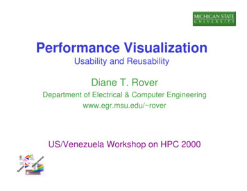
White PaperTo aid in understanding, viewing the behavior in a packet capture can be helpful. This packet capture2 was taken from a VLAN trunkon a Cisco switch where the native VLAN is VLAN 1 (the default), and VLAN 5 is active on it as well. The switch is utilizing PVRST , butthe same behavior applies to PVST in regards to utilization of SSTP.Three different BPDUs are of interest. The first is a standard IEEE BPDU designed to interoperate with the CST. It is untagged and sentto the reserved multicast MAC address of 0180.C200.0000.The second BPDU is a SSTP BPDU. It is tagged as VLAN 5 and sent to the special multicast MAC address of 0100.0CCC.CCCD.In the third BPDU we see an additional SSTP BPDU for VLAN 1, untagged, and sent to the same12This has also been referred to as Secure Socket Tunneling Protocol.Packet capture provided by PacketLife.net - http://www.packetlife.netarista.com3
White Paperspecial multicast MAC address as the second. This represents the native VLAN to other Cisco switches running PVRST or PVST What this accomplishes is a tunneling effect through, for example, an Arista switch environment running MSTP. These SSTP BPDUswould not be understood by the Arista switches, so they would then be flooded as a regular multicast. This allows PVST BPDUs tocross through a MST region and be received by another Cisco PVST switch on the other side while still maintaining the ability tointeract with the CST of a MST environment via IEEE standard BPDUs.What Makes MSTP Proprietary For CiscoCisco switches running MSTP do so without being fully compliant with the 802.1s standard when interacting with non-MST domainsby utilizing a proprietary feature called PVST Simulation3. PVST Simulation was designed for Cisco switches running MST connectedto non- MST domains and is automatically enabled on a per-port basis when non-MST BPDUs are received. BPDUs received on VLAN1 are received and processed normally within MST. BPDUs received on VLANs other than VLAN 1 go through a PVST Simulationcheck.arista.com4
White PaperThis check enforces two rules: If the root bridge for CIST is within a non-MST region (a region where MST isn’t running), the spanning-tree priority of VLANs 2and above within that domain must be better (lesser) than that of VLAN 1. If the root bridge for CIST is within a MST region, VLANs 2 and above defined in the non-MST domains must have theirspanning-tree priorities worse (greater) than that of the CIST root.A violation of these rules will place the port on the Cisco switch port into a non-forwarding state until the “inconsistency” thattriggered the violation is resolved.PVST Simulation is also responsible for the interoperability mechanism that MSTP cannot provide alone when working with Cisco’sPVST or PVRST implementations. MSTP by itself cannot affect root bridge election outside of the CIST. This can be a problem forattached Cisco switches running their per-VLAN spanning tree implementations because SSTP BPDUs would tunnel through a CiscoMSTP environment as described in the “What makes PVST Proprietary” section if it didn’t have this added functionality of PVSTSimulation.PVST Simulation addresses this by taking the bridge information received from a boundary port and sends a BPDU for every activeVLAN on that link. This allows Cisco switches running MST to affect root bridge election on all VLANs when interacting with switchesrunning per-VLAN spanning tree implementations. This is why Cisco recommends starting MST migration from the Enterprisedistribution layer down in a typical 3-tier model with a routed core, and ensuring that the distribution switch is configured to be theroot bridge of the CIST in the example provided in their PVST to MST migration document - because it conforms with the secondrule of the PVST Simulation check.Arista switches implement MSTP per the 802.1s standard without any additional interoperability mechanisms.Default Spanning Tree Path CostsArista switches use default port path costs as defined in IEEE 802.1D-2004:arista.com5
White PaperARISTA.21:27:12#sh spanVL1Spanning tree enabled protocol rapid-pvstRoot IDPriority4097Address001c.730c.25f0This bridge is the rootBridge ID Priority4097 (priority 4096 sys-id-ext 1)Address001c.730c.25f0Hello Time 2.000 sec Max Age 20 sec Forward Delay 15 secInterfaceRoleStateCostPrio.NbrType----------- ---------- ---------- ------ ---------- ----------------Et1designated forwarding 20000128.1P2p Boundary(STP)Et2designated forwarding 20000128.2P2p Boundary(STP)Et4designated forwarding 20000128.4P2p Boundary(STP)Et6designatedforwarding20000128.4P2p Boundary(STP)Cisco switches utilizing PVST or PVRST use port path costs defined in the older IEEE 802.1D-1998 standard by default, which doesnot provide enough granularity for modern networks utilizing 40Gb and 100Gb:CISCO#sh spanVLAN0001Spanning tree enabled protocol rstpRoot IDPriority4097Address001c.730c.25f0This bridge is the rootHello Time 2 sec Max Age 20 sec Forward Delay 15 secBridge ID Priority32769 (priority 32768 sys-id-ext 1)Address001d.a143.f900Hello Time 2 sec Max Age 20 sec Forward Delay 15 secAging Time 300InterfaceRole State Cost Prio.NbrType----------- ---- ----- ---- ---------- ----------------Gi0/1Root FWD4128.1P2pGi0/2Altn BLK4128.2P2pGi0/3Altn BLK4128.3P2pGi0/4arista.comAltnBLK4128.4P2p6
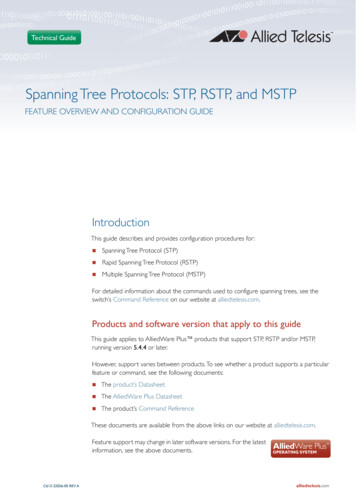
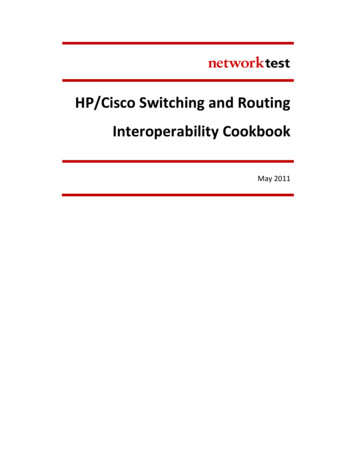
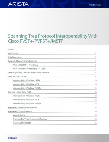
White PaperThis is important to know as it can have effects on path choice in spanning tree environments. For example, in the followingscenario, the upstream Cisco switch influences path choice due to its lower advertised cost to reach the root bridge:This can cause suboptimal traffic forwarding in situations where path speeds are not the same, such as in the following twoscenarios. In both cases, the upstream Cisco switch influences path selection through a less desirable path:either at the Leaf or Spinelayer as appropriate.Figure 4: vEOSarista.com7
White PaperThis issue can be addressed by utilizing the spanning-tree pathcost method long global configuration mode command on a Ciscoswitch running PVST or PVRST .CISCO(config)#spanning-tree pathcost method long!!The Gigabit interfaces on this Cisco switch now have costs that are more in line with IEEE802.1D-2004CISCO#sh spanVLAN0001Spanning tree enabled protocol rstpRoot IDPriority4097Address001c.730c.25f0Cost20000Port1 (GigabitEthernet0/1)Hello Time 2 sec Max Age 20 sec Forward Delay 15 secBridge ID Priority32769 (priority 32768 sys-id-ext 1)Address001d.a143.f900Hello Time 2 sec Max Age 20 sec Forward Delay 15 secAging Time 300Interface Role Sts Cost Prio.Nbr Type--------- ---- --- ----- -------- ----Gi0/1Root FWD 20000 128.1P2pGi0/2Altn BLK 20000 128.2P2pGi0/3Altn BLK 20000 128.3P2pGi0/4AltnBLK20000 128.4P2pLastly, this is not an issue for Cisco switches running MSTP, as the more granular STP path costs are used by default.arista.com8
White PaperPort Channel BehaviorTwo LAGs are configured between the Arista and Cisco switches. Only VLAN 1 is present. Rapid-PVST is utilized on the Arista switchwith PVRST being utilized on the Cisco switch. The Arista switch is configured with a lower priority to become the root bridge.! Note current spanning tree topologyARISTA.10:04:48(config)#sh spanVL1Spanning tree enabled protocol rapid-pvstRoot IDPriority4097Address001c.730c.25f0This bridge is the rootBridge ID Priority4097 (priority 4096 sys-id-ext 1)Address001c.730c.25f0Hello Time 2.000 sec Max Age 20 sec Forward Delay 15 secInterface RoleStateCost Prio.Nbr Type--------- ---------- ---------- ---- -------- ----Po1designated forwarding 19999 128.100 P2pPo2designated forwarding 19999 128.101 P2p!! One item of interest is how the spanning tree port costs are presented differently. Onthe Arista switch, the cost of Po1 and Po2 was 19,999. On the Cisco switch, it is 3CISCO(config)#do sh spanVLAN0001Spanning tree enabled protocol rstpRoot IDPriority4097Address001c.730c.25f0Cost3Port56 (Port-channel1)Hello Time 2 sec Max Age 20 sec Forward Delay 15 secBridge IDPriority32769 (priority 32768 sys-id-ext 1)Address001d.a143.f900Hello Time 2 sec Max Age 20 sec Forward Delay 15 secAging Time 300Interface RoleSts Cost Prio.Nbr Type--------- ------ ---- --- -------- -------Po1RootFWD 3128.56P2pPo2AltnBLK 3128.64P2p!! Now interface Et1 which is a member of Po1 on the Arista switch will be shut down.Observe the resulting spanning tree topologyARISTA.10:05:48(config)#int et1ARISTA.10:38:11(config-if-Et1)#shut!! No change is seen on the Arista switcharista.com9
White PaperARISTA.10:39:15(config)#sh spanVL1Spanning tree enabled protocol rapid-pvstRoot IDPriority4097Address001c.730c.25f0This bridge is the rootBridge ID Priority4097 (priority 4096 sys-id-ext 1)Address001c.730c.25f0Hello Time 2.000 sec Max Age 20 sec Forward Delay 15 secInterface RoleStateCost Prio.Nbr Type--------- ------------- ----- -------- --------Po1designated forwarding 19999 128.100 P2pPo2designated forwarding 19999 128.101 P2p!! The Cisco switch on the other hand updates the cost of Po1 to 4. This in turn causesa change in the spanning tree topology as Po1 is moved into an alternate role, blockingstate. Po2 is moved into a root role, forwarding stateCISCO(config)#do sh spanVLAN0001Spanning tree enabled protocol rstpRoot IDPriority4097Address001c.730c.25f0Cost3Port64 (Port-channel2)Hello Time 2 sec Max Age 20 sec Forward Delay 15 secBridge ID Priority32769 (priority 32768 sys-id-ext 1)Address001d.a143.f900Hello Time 2 sec Max Age 20 sec Forward Delay 15 secAging Time 300Interface Role Sts Cost Prio.Nbr Type--------- ---- ---- --- -------- -------Po1Altn BLK 4128.56P2pPo2Root FWD 3128.64P2pIt is important to note that Arista switches only update the STP cost for a port channel upon its creation to favor the port channelover a single link that has the same speed as one of the port channel’s members. For example, the STP cost for a 1Gb link on an Aristaswitch is 20,000. A port channel on the same switch made up of 1Gb links has a STP cost of 19,999 making it more desirable over asingle 1Gb link.Arista switches do not update the STP cost as of a port channel in the case of a member link failure. This is done to improve stabilityby avoiding STP reconvergence events per the IEEE 802.1D-2004 standard:“Where intermediate link speeds are created as a result of the aggregation of two or more links of the same speed (see IEEE Std802.3-2002), it can be appropriate to modify the recommended values shown in Table 17-3 to reflect the change in link speed.However, as the primary purpose of the Path Cost is to establish the active topology of the network, it can be inappropriate for thePath Cost to track the effective speed of such links too closely, as the resultant active topology could differ from that intended by thenetwork administrator. For example, if the network administrator had chosen an active topology that makes use of aggregated linksfor resilience (rather than for increased data rate), it would be inappropriate to cause a Spanning Tree topology change as a result ofone of the physical links in an aggregation failing. Similarly, with links that can autonegotiate their data rate, reflecting such changesof data rate in changes to Path Cost is not necessarily appropriate, depending upon the intent of the network administrator. As adefault, dynamic changes of data rate shall not automatically cause changes in Port Path Cost.”arista.com10
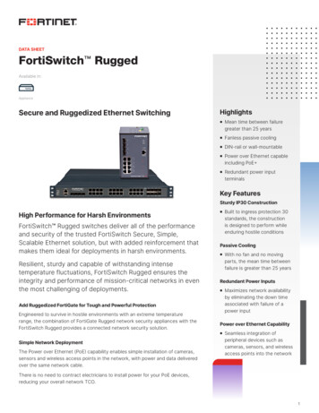
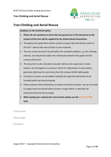
White PaperIn the following scenario, we see how a change in port channel membership due to a faulty link causes an STP reconvergence event:1.Traffic is flowing normally through CISCO1 toward the root bridge.2.A 1Gb member link from the port channel between CISCO1 and the root bridge goes down.3.CISCO1 updates the STP cost to 4, making that path less desirable than through CISC02.4.The switch at the bottom of the diagram begins receiving superior BPDUs on Port 2 due to a lower cost to reach the root bridge.It transitions Port 1 to a blocking state while transitioning Port 2 to a forwarding state. This is a STP reconvergence event.5.Traffic is now forwarded through CISCO2 and will remain that way until the member link issue is resolved, which will causeanother STP reconvergence event as the topology returns back to as it was in Step 1.This is a standard behavior with all spanning tree protocols on IOS-based Cisco switches. NX- OS-based platforms do not follow thismodel and instead base the STP cost of a port channel on its configured members - not their operational status (like Arista switches).Applying the same scenario with Arista switches, it can be observed that the switch at the bottom of the diagram doesn’t see achange. This avoids a STP reconvergence event and maintains a stable topology. This also allows the faulty member link to berepaired without causing further STP reconvergence events.arista.com11
White PaperTo address this issue on an IOS-based Cisco switch, you may configure the spanning tree cost manually on the port channel with thespanning-tree cost interface command. This will make the STP cost of the port channel static regardless of the state of a memberlink:CISCO(config-if)#int po1CISCO(config-if)#spanning-tree cost 19999!! The STP cost of Po1 is now 19,999CISCO(config-if)#do sho span int po1VlanRole Sts Cost---------------- ---- --- --------VLAN0001Root FWD 19999!! One of Po1’s member links is shutCISCO(config)#int gi0/1CISCO(config-if)#shut!! The STP cost of Po1 is unchangedCISCO(config-if)#do sh span int po1Prio.Nbr Type-------- le Sts CostPrio.Nbr Type---------------- ---- --- --------- -------- -------------------------------VLAN0001Root FWD 19999128.56P2pThe downside of this is that you will need to ensure you utilize the correct port cost depending on the situation.Another difference in port channel behavior is the initially-assigned STP cost. On an Arista switch, a port channel made up of two1Gb interfaces or four 1Gb interfaces has the same cost. For Cisco switches, the cost is a function of the aggregated bandwidth ofthat particular port channel’s configured member links. So in most cases, the port channel on a Cisco switch will have better costarista.com12
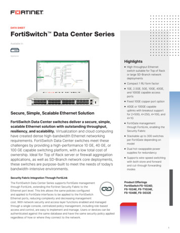
White Paperall things being equal. Take the following scenario for example where the Cisco switch has been configured with the spanning-treepathcost method long command and initially only one 1Gb link is in the port channel:! The Arista switch shows a cost of 19,999 for Po1ARISTA.10:12:56(config)#sh span int po1InstanceRoleStateCostPrio.Nbr Type---------------- ---------- ---------- --------- -------- -------------------VL1designated forwarding 19999128.100 P2p!! The Cisco switch shows a cost of 20,000 for Po1CISCO#sh span int po1VlanRole Sts CostPrio.Nbr Type---------------- ---- --- --------- -------- -------------------------------VLAN0001Altn BLK 20000128.56P2p!! Now the second interface will be added to Po1 on both sidesARISTA.10:16:29(config)#int et2ARISTA.10:19:38(config-if-Et2)#channel-group 1 mode active!CISCO(config)#int gi0/2CISCO(config-if)#channel-group 1 mode active!! The Arista switch still shows a cost of 19,999 for Po1ARISTA.10:19:42(config-if-Et2)#sh span int po1InstanceRoleStateCostPrio.Nbr Type---------------- ---------- ---------- --------- -------- -------------------VL1designated forwarding 19999128.100 P2p!! The Cisco switch however now shows a cost of 10,000CISCO(config-if)#do sh span int po1VlanRole Sts CostPrio.Nbr Type---------------- ---- --- --------- -------- -------------------------------VLAN0001Root FWD 10000128.56P2pThis could also be worked around with the spanning-tree cost interface command on Po1 of the Cisco switch - with the samecaveats.Use Case - Arista MSTPIn these scenarios, an Arista DCS-7048T-4S-F on 4.13.0 is connected to a Cisco C2960 on 12.2(35) SE5, LAN Base via four linksconfigured as trunks initially allowing all VLANs between the two switches. VLANs 1, 10, and 20 are active on both switches. Initially,all configurations are default.arista.com13
White PaperInteroperability With Cisco PVST Arista switches only send MST0 BPDUs on the default VLAN (VLAN 1 by default). When interoperating with PVST , it is important tokeep this in mind when it comes to root bridge election. For example, consider the following scenario: Arista switch is configured with MST, all VLANs are in MST0, and priority is configured for 4,096. VLAN 1, 10, and 20 are active. Cisco switch is attached, configured for PVST , and default priority (32,768). VLAN 1, 10, and 20 are active. The links connecting these two switches are configured as trunks and allow all VLANs.In this case, the Arista switch will be the root bridge for VLAN 1, but the Cisco switch will consider itself the root bridge for VLANs 10and 20 since it will only receive BPDUs from the Arista switch for VLAN 1. Again, an Arista switch configured for MST will only sendBPDUs on the default VLAN.For the following use case, all VLANs on the Arista switch running MST are mapped to MST0. Note spanning tree topology.arista.com14
White Paper! The Arista switch claims itself to be root of MST0, and places all of its ports into adesignated role, forwarding state. Also note that the connected ports between these twoswitches are seen as boundary ports because the Cisco switch is not running MSTARISTA.14:55:10#sh spanning-treeMST0Spanning tree enabled protocol mstpRoot IDPriority32768Address001c.730c.25f0This bridge is the rootBridge ID Priority32768 (priority 32768 sys-id-ext 0)Address001c.730c.25f0Hello Time 2.000 sec Max Age 20 sec Forward Delay 15 secInterfaceRoleStateCostPrio.Nbr Type---------------- ---------- ---------- --------- -------- -------------------Et1designated forwarding 20000128.1P2p Boundary(STP)Et2designated forwarding 20000128.2P2p Boundary(STP)Et4designated forwarding 20000128.4P2p Boundary(STP)Et6designated forwarding 20000128.6P2p Boundary(STP)!! The Cisco switch agrees that the Arista switch is the root bridge for VLAN 1 becausethe Arista switch has a superior bridge priority of 32768. However, it claims itself tobe the root bridge for VLANs 10 and 20. Also note that port Gi0/1 is in a Root port rolefor VLAN 1, but in a Designated port role for VLANs 10 and 20CISCO#sh spanning-treeVLAN0001Spanning tree enabled protocol ieeeRoot IDPriority 32768Address001c.730c.25f0Cost4Port1 (GigabitEthernet0/1)Hello Time 2 sec Max Age 20 sec Forward Delay 15 secBridge ID Priority 32769 (priority 32768 sys-id-ext 1)Address001d.a143.f900Hello Time 2 sec Max Age 20 sec Forward Delay 15 secAging Time 300InterfaceRole Sts CostPrio.Nbr Type---------------- ---- --- --------- -------- -------------------------------Gi0/1Root FWD 4128.1P2pGi0/2Altn BLK 4128.2P2pGi0/3Altn BLK 4128.3P2pGi0/4Altn BLK 4128.4P2pVLAN0010Spanning tree enabled protocol ieeeRoot IDPriority32778Address001d.a143.f900This bridge is the rootHello Time 2 sec Max Age 20 sec Forward Delay 15 secBridge ID Priority32778 (priority 32768 sys-id-ext 10)Address001d.a143.f900Hello Time 2 sec Max Age 20 sec Forward Delay 15 secAging Time 300arista.com15
White -------------------------P2pP2pP2pP2pSpanning tree enabled protocol ieeeRoot IDPriority32788Address001d.a143.f900This bridge is the rootHello Time 2 sec Max Age 20 sec Forward Delay 15 secBridge ID Priority32788 (priority 32768 sys-id-ext 20)Address001d.a143.f900Hello Time 2 sec Max Age 20 sec Forward Delay 15 secAging Time 300InterfaceRole Sts CostPrio.Nbr Type---------------- ---- --- --------- -------- -------------------------------Gi0/1Desg FWD 4128.1P2pGi0/2Back BLK 4128.2P2pGi0/3Back BLK 4128.3P2pGi0/4Back BLK 4128.4P2p!! This reflects the per-VLAN behavior of PVST versus the fact that Arista switchesrunning MST only send BPDUs on the default VLAN (VLAN 1 by default) and that MSTP byitself is not VLAN aware. Even if the Arista switch were to be configured with apriority of 4096 for MST0 (to which VLANs 1, 10, and 20 are mapped), it would have noeffect outside of VLAN 1 in the Cisco switch’s viewARISTA.15:49:35(config)#spanning-tree mst 0 priority 4096!! Note the updated bridge priority for VLAN 1, but no changes to VLAN 10 or 20CISCO#sh spanVLAN0001Spanning tree enabled protocol ieeeRoot IDPriority4096Address001c.730c.25f0Cost4Port1 (GigabitEthernet0/1)Hello Time 2 sec Max Age 20 sec Forward Delay 15 secBridge ID Priority32769 (priority 32768 sys-id-ext 1)Address001d.a143.f900Hello Time 2 sec Max Age 20 sec Forward Delay 15 secAging Time 300InterfaceRole Sts CostPrio.Nbr Type---------------- ---- --- --------- -------- -------------------------------Gi0/1Root FWD 4128.1P2pGi0/2Altn BLK 4128.2P2pGi0/3Altn BLK 4128.3P2pGi0/4Altn BLK 4128.4P2parista.com16
White PaperVLAN0010Spanning tree enabled protocol ieeeRoot IDPriority32778Address001d.a143.f900This bridge is the rootHello Time 2 sec Max Age 20 sec Forward Delay 15 secBridge ID Priority32778 (priority 32768 sys-id-ext 10)Address001d.a143.f900Hello Time 2 sec Max Age 20 sec Forward Delay 15 secAging Time sgBackBackSts--FWDBLKBLKCost--------444Gi0/4Back BLK ----------------P2pP2pP2p128.4P2pVLAN0020Spanning tree enabled protocol ieeeRoot IDPriority 32788Address001d.a143.f900This bridge is the rootHello Time 2 sec Max Age 20 sec Forward Delay 15 secBridge IDPriority 32788 (priority 32768 sys-id-ext 20)Address001d.a143.f900Hello Time 2 sec Max Age 20 sec Forward Delay 15 secAging Time 15InterfaceRole Sts CostPrio.Nbr Type---------------- ---- --- --------- -------- -------------------------------Gi0/1Desg FWD 4128.1P2pGi0/2Back BLK 4128.2P2pGi0/3Back BLK 4128.3P2pGi0/4 Back BLK 4 128.4 P2p!! Now the Arista switch will be returned to default configuration and the Cisco switchwill be configured for a priority of 4096 for all VLANs. Note the resulting spanning treetopologyARISTA.15:49:40(config)#no spanning-tree mst 0 priority 4096!CISCO(config)#spanning-tree vlan 1,10,20 priority 4096!! The results are as expected. The Cisco switch sees itself as the root bridge for allVLANsCISCO#sh spanVLAN0001Spanning tree enabled protocol ieeeRoot IDBridge IDPriority4097Address001d.a143.f900This bridge is the rootHello Time 2 sec Max Age 20 sec Forward Delay 15 secPriority4097 (priority 4096 sys-id-ext 1)Address001d.a143.f900Hello Time 2 sec Max Age 20 sec Forward Delay 15 secAging Timearista.com30017
White PaperInterfaceRole Sts CostPrio.Nbr Type---------------- ---- --- --------- -------- -------------------------------Gi0/1Desg FWD 4128.1P2pGi0/2Desg FWD 4128.2P2pGi0/3Desg FWD 4128.3P2pGi0/4Desg FWD 4128.4P2pVLAN0010Spanning tree enabled protocol ieeeRoot IDPriority4106Address001d.a143.f900This bridge is the rootHello Time 2 sec Max Age 20 sec Forward Delay 15 secBridge ID Priority4106 (priority 4096 sys-id-ext 10)Address001d.a143.f900Hello Time 2 sec Max Age 20 sec Forward Delay 15 secAging Time 300InterfaceRole Sts CostPrio.Nbr Type---------------- ---- --- --------- -------- -------------------------------Gi0/1Desg FWD 4128.1P2pGi0/2Desg FWD 4128.2P2pGi0/3Desg FWD 4128.3P2pGi0/4Desg FWD 4128.4P2pVLAN0020Spanning tree enabled protocol ieeeRoot IDPriority4116Address001d.a143.f900This bridge is the rootHello Time 2 sec Max Age 20 sec Forward Delay 15 secBridge ID Priority4116 (priority 4096 sys-id-ext 20)Address001d.a143.f900Hello Time 2 sec Max Age 20 sec Forward Delay 15 secAging Time 300InterfaceRole Sts CostPrio.Nbr Type---------------- ---- --- --------- -------- -------------------------------Gi0/1Desg FWD 4128.1P2pGi0/2Desg FWD 4128.2P2pGi0/3Desg FWD 4128.3P2pGi0/4Desg FWD 4128.4P2p!! The Arista switch sees the Cisco switch as the root bridge for MST0ARISTA.16:11:50#sh spanMST0Spanning tree enabled protocol mstpRoot IDPriority4097Address001d.a143.f900Cost20000 (Ext) 0 (Int)Port1 (Ethernet1)Hello Time 2.000 sec Max Age 20 sec Forward Delay 15 secBridge ID Priority32768 (priority 32768 sys-id-ext 0)Address001c.730c.25f0Hello Time 2.000 sec Max Age 20 sec Forward Delay 15 secInterfaceRoleStateCostPrio.Nbr Type---------------- ---------- ---------- --------- -------- -------------------Et1rootforwarding 20000128.1P2p Boundary(STP)Et2alternate discarding 20000128.2P2p Boundary(STP)Et4alternate discarding 20000128.4P2p Boundary(STP)Et6arista.comalternatediscarding 20000128.6P2p Boundary(STP)18
White PaperInteroperability With Cisco MSTP! All VLANs on the Arista and Cisco switches are mapped to MST0. Note spanning treetopology. The Arista switch sees itself as the root bridge for MST0ARISTA.10:20:19#sh spanMST0Spanning tree enabled protocol mstpRoot IDPriority32768Address001c.730c.25f0This bridge is the rootBridge ID Priority32768 (priority 32768 sys-id-ext 0)Address001c.730c.25f0Hello Time 2.000 sec Max Age 20 sec Forward Delay 15 secInterfaceRoleStateCostPrio.Nbr Type---------------- ---------- ---------- --------- -------- -------------------Et1designated forwarding 20000128.1P2pEt2designated forwarding 20000128.2P2pEt4designated forwarding 20000128.4P2pEt6designated forwarding 20000128.6P2p!! As expected, the Cisco switch agrees that the Arista switch is the root bridge forMST0, due to the Arista switch having a lower MAC addressCISCO#sh spanning-treeMST0Spanning tree enabled protocol mstpRoot IDPriority32768Address001c.730c.25f0Cost0Port1 (GigabitEthernet0/1)Hello Time 2 sec Max Age 20 sec Forward Delay 15 secBridge ID Priority32768 (priority 32768 sys-id-ext 0)Address001d.a143.f900Hello Time 2 sec Max Age 20 sec Forward Delay 15 secInterfaceRoleStateCostPrio.Nbr Type---------------- ---------- ---------- --------- -------- ltnBLK20000128.4P2p!! Now the Arista switch will be configured to have VLAN 20 in MST1. Note resultingspanning tree topologyARISTA.10:36:47(config)#spanning-tree mst configurationARISTA.10:36:57(config-mst)#instance 1 vlans 20!! The Arista switch sees itself as the root bridge for both MST0 and MST1. Also note theboundary ports due to mismatched MST configuration between the two switches which hasresulted in two discrete MST regions being createdARISTA.10:37:39#sh spanMST0Spanning tree enabled protocol mstpRoot IDPriority32768Address001c.730c.25f0This bridge is the rootarista.com19
White PaperBridge IDPriority32768 (priority 32768 sys-id-ext 0)Address001c.730c.25f0Hello Time 2.000 sec Max Age 20 sec Forward Delay 15 secInterfaceRoleStateCostPrio.Nbr Type---------------- ---------- ---------- --------- -------- -------------------Et1designated forwarding 20000128.1P2p BoundaryEt2desig
802.1D-2004 CISCO#sh span VLAN0001 Spanning tree enabled protocol rstp Root ID Priority 4097 Address 001c.730c.25f0 Cost 20000 Port 1 (GigabitEthernet0/1) Hello Time 2 sec Max Age 20 sec Forward Delay