Transcription
SUGGESTED SPECIFICATIONSteel Pipe for Water TransmissionCement Mortar Lined and CoatedAWWA C200PART 1: GENERAL1.01 DescriptionScope of Work: Provide and install steel pipe of the sizes and in the locations shown on the Plans and asspecified herein.1.02 Quality AssuranceCommercial Standards: Unless otherwise stated, the latest edition for any commercial standards and allmanufacturing tolerances referenced therein shall apply.ANSI/AWS D1.1Structural Welding Code‐ SteelANSI/AWWA C200Steel Water Pipe—6 In. (150 mm) and LargerANSI/AWWA C205Cement mortar Protective Lining and Coating for Steel Water Pipe – 4 In. (100mm) and Larger‐ Shop AppliedANSI/AWWA C206Field Welding of Steel Water PipeANSI/AWWA C207Steel Pipe Flanges for Waterworks Service—Sizes 4 In. Through 144 In. (100 mmthrough 3,600 mm)ANSI/AWWA C208Dimensions for Fabricated Steel Water Pipe FittingsANSI/AWWA C604Installation of Buried Steel Pipe – 4 inch and LargerASME Section IXAWWA M11International Boiler & Pressure Vessel Code: Welding and Brazing QualificationsSteel Water Pipe: A Guide for Design and InstallationNorthwest Pipe CompanySuggested Specification for Steel Pipe for Water Transmission Page 1
SSPC‐PA 2A.Systems and Specifications SSPC Painting Manual, Volume 2 Chapter 7:Measurement of Dry Coating Thickness with Magnetic GagesQualifications1.Manufacturers who are fully experienced, reputable, and qualified in the manufacture of theproducts to be furnished shall furnish all steel pipe and fittings. The pipe and fittings shall bedesigned, constructed and installed in accordance with the best practices and methods and shallcomply with these specifications as applicable.2.Pipe cylinders, lining, coating and fabrication of specials shall be the product of one manufacturerthat has not less than five years successful experience manufacturing pipe of the particular typeand size indicated. The Pipe Manufacturer must have a certified quality assurance program and allmanufacturing, coating or lining operations must be performed at one facility. This certifiedprogram shall be ISO 9001:2000 or other equivalent nationally recognized program as approved bythe Engineer.1.03 SubmittalsA.Shop DrawingsDrawings shall be submitted to the Engineer for approval and shall include the following:B.C.1.Pipeline layout showing stations and elevations.2.Details of standard pipe, joints, specials and fittings.Design1.Calculations for verification of pipe design and fittings reinforcement and/or test data.2.Details of joint bonding and field welded joint restraint calculations.Certifications1.The Contractor shall furnish a certified affidavit of compliance that meets or exceeds therequirements of these specifications for all pipe and fittings furnished.2.Pipe linings in contact with potable water shall be NSF certified.1.04 VerificationA.Inspections1.B.All pipe shall be subject to inspection at the place of manufacture in accordance with the provisionsof AWWA C200 and AWWA coating and lining standard as supplemented by the requirementsherein.TestsNorthwest Pipe CompanySuggested Specification for Steel Pipe for Water Transmission Page 2
C.1.Except as modified herein, all materials used in the manufacture of the pipe shall be tested inaccordance with the requirements of AWWA C200 and AWWA coating and lining standards.2.The Contractor shall perform required tests at no additional cost to the Owner. The Engineer shallhave the right to witness all testing conducted by the Contractor, provided that the Contractor’sschedule is not delayed for the convenience of the Engineer.Welding Requirements1.D.All welding procedures used to fabricate pipe shall be qualified under the provision of ASMESection IX.Welder Qualifications1.Skilled welders, welding operators, and tackers who have had adequate experience in the methodsand materials to be used shall do all welding. Welders shall maintain current qualifications underthe provisions of ASME Section IX. Machines and electrodes similar to those in the work shall beused in qualification tests. The Contractor shall furnish all material and bear the expense ofqualifying welders.1.05 Handling, Storage and ShippingA.Coated pipe shall be shipped on padded bunks with nylon belt tie‐down straps or padded bandinglocated approximately over stulling.B.Coated pipe shall be stored on padded skids, sand or dirt berms, sand bags, old tires or other suitablemeans so that coating will not be damaged or cracked.C.Coated pipe shall be handled with wide belt slings. Chains, cables or other equipment likely to causedamage or cracking to the pipe coating or lining shall not be used.D.Prior to shipment, coated pipe shall be visually inspected for damage to the coating. Repair any damageto coating per AWWA C205.1.06 MarkingsA.The Contractor shall legibly mark all pipes and specials in accordance with the laying schedule andmarking diagram. Each pipe shall be numbered in sequence and said number shall appear on the layingschedule and marking diagram in its proper location for installation. All special pipe sections and fittingsshall be marked at each end with top field centerline.PART 2: PRODUCTS2.01 MaterialsNorthwest Pipe CompanySuggested Specification for Steel Pipe for Water Transmission Page 3
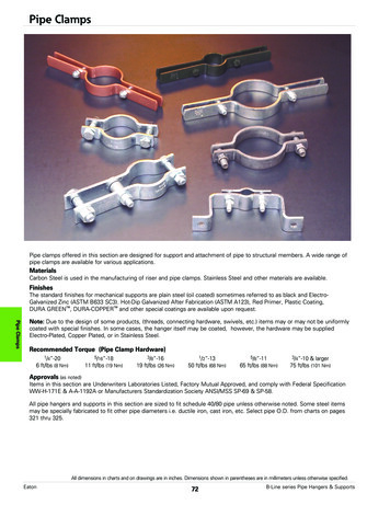
A.PipeSteel pipe shall conform to AWWA C200. Steel plate used in the manufacture and fabrication of steel pipeshall meet the requirements of AWWA C200. All longitudinal and girth seams, whether straight or spiral, shallbe butt‐welded using an approved electric‐fusion‐weld process.1.SPECIFIER OPTION: Pipe shall be designed for psi working pressure with an additionalpsi allowance for surge. Pipe design shall be in accordance with AWWA M11. (in no case shall designbe less than 150 psi or 75 psi for surge)OR:Pipe pressure zones shall be designed for a maximum of 50% of yield at working pressure and 75% of yieldat the maximum pressure (test or transient) as shown on the plans. (In no case shall design pressure be lessthan 150 psi for working or 225 psi for maximum pressure.)B.C.2.Pipe shall be bedded and backfilled per the Plan details utilizing an E’ value for design check perAWWA M11 Chapter 5, External Loads on Buried Pipe.3.Pipe is to be furnished principally in 50‐feet net laying lengths with shorter lengths, field trimpieces and closure pieces as required by Plan and profile for location of elbows, tees, reducers andother in‐line fittings. Or, as required for construction. The pipe fabricator shall prepare a pipe layingschedule showing the location of each piece by mark number with station and invert elevation ateach bell end.Fittings1.Unless otherwise shown on the Plans, all specials and fittings shall conform to AWWA M11 and thedimensions of AWWA C208. Pipe material used in fittings shall be of the same material andpressure class as the adjoining pipe. The radius of elbows shall be 2 ½ times the pipe diameter andthe maximum miter angle on each section of the elbow shall not exceed 11 ¼‐degrees (one cutelbow up to 22 ½‐degrees). If elbow radius is less than 2 ½ times the pipe diameter, stresses shallbe checked per AWWA M‐11.2.Fittings shall be equal in pressure class design as the adjoining pipe. Specials and fittings, unlessotherwise shown on the Plans, shall be made of segmental welded sections from hydrostaticallytested pipe, with ends compatible with the type of joint or coupling specified for the pipe. All weldsmade after hydrostatic testing of the straight sections of pipe shall be tested per the requirementsof AWWA C200.Joints1.Rolled Groove Rubber Gasket JointNorthwest Pipe CompanySuggested Specification for Steel Pipe for Water Transmission Page 4
2.3.4.a.The standard joint shall be a rolled groove rubber gasket joint unless otherwise noted on thePlans. Rolled groove rubber gasket joints shall conform to AWWA C200 and as shown inChapter 6 of AWWA M11.b.The O‐ring gasket shall have sufficient volume to approximately fill the area of the groove andshall conform to AWWA C200.c.The O‐ring gasket joint shall be used where unrestrained joints are shown on the plans. Thedesign maximum joint deflection or offset shall be a 1‐inch joint pull.d.Rolled groove rubber gasket joints may be furnished only by a Manufacturer who hasfurnished pipe with joints of similar design for comparable working pressure and pipediameters has been in successful service for a period of at least five years.Lap Welda.Lap weld joints shall conform to AWWA C200 and as shown in Chapter 6 of AWWA M11.b.Lap field welded joints shall be used where restrained joints are required or indicated on thePlans. The design maximum joint deflection or offset shall be a 1‐inch joint pull.c.Lap welded joints shall be welded either externally or internally. Holdbacks for coating andlinings shall be provided as shown on the approved shop drawings. “Weld‐after‐backfill” ofinterior welds may be performed any time after joint completion and backfilling has beencompleted.d.Unless otherwise shown on the Plans, all field joints shall be lap welded for diameters 78inches and greater.Mechanical Couplingsa.Mechanical couplings where indicated on the Plans shall be Smith Blair Style 411, Baker Style200, Romac Style 400, ClampTite, or equal.b.Insulating mechanical couplings where indicated on the Plans shall be double insulated SmithBlair Style 416, Baker Style 216, or equal for working pressures up to 150 psi.c.Couplings for buried service shall have all metal parts painted with polyurethane paintconforming to AWWA C222 or epoxy per AWWA C210.d.Pipe ends for mechanical couplings shall conform to AWWA C200 and M11. The shop appliedoutside coating shall be held back as required for field assembly of the mechanical coupling.Harness lugs or rings shall be painted with polyurethane conforming to AWWA C222.e.Pipe for use with sleeve‐type couplings shall have plain ends at right angles to the axis.FlangesNorthwest Pipe CompanySuggested Specification for Steel Pipe for Water Transmission Page 5
5.a.Flanges shall be in accordance with AWWA C207 Class D for operating pressures to 175 psi on4‐inch through 12‐inch diameter, and operating pressures to 150 psi on diameters over 12inches.b.Flanges shall be AWWA C207 Class E for operating pressures over 150 psi to 275 psi or shallbe AWWA C207 Class F for pressures to 300 psi (drilling matches ANSI B 16.5 Class 250).c.Shop lining and coating shall be continuous to the end of the pipe or back of the flange.Flange faces shall be shop coated with a soluble rust preventive compound.d.Gaskets shall be per C207 Table 1.Bolts and Nuts for Flangesa.6.Bolts for flanges shall be carbon steel, ASTM A 193, Grade B7 and nuts shall be ASTM A 194,Grade 2H heavy hex in accordance with AWWA C207.All unwelded pipe joints shall be bonded for electrical continuity in accordance with the PipeManufacturer’s recommendations unless otherwise specified in the Plans.2.02 Linings and CoatingsA.B.Cement Mortar Lining1.Interior surface of all steel pipe, fittings and specials shall be lined in the shop with cement mortarlining in conformity with AWWA C205.2.Holdbacks shall be left bare and be provided as shown on the approved shop drawings. Holdbacksshall be filled with cement mortar after joint completion per AWWA C205.3.Defective linings as identified in AWWA C205 shall be removed from the pipe wall and shall bereplaced to the full thickness required. Defective linings shall be cut back to a square shoulder inorder to avoid feather edged joints.4.Fittings shall be cement mortar lined per AWWA C205. Pipe and fittings too small to cement mortarline may be lined with AWWA C210 epoxy or AWWA C222 polyurethane.5.Cement mortar lining shall be kept moist during storage and shipping to limit shrinkage cracking.The supplier shall provide a polyethylene or other suitable bulkhead on the ends of the pipe and onall special openings to prevent drying out the lining. All bulkheads shall be substantial enough toremain intact during shipping and storage until the pipe is installed. Do not remove bulkheads priorto installation.Cement Mortar Coating1.All pipe shown on the Plans to be cement mortar coated shall be coated with minimum ¾” ofcement mortar in accordance with AWWA C205.Northwest Pipe CompanySuggested Specification for Steel Pipe for Water Transmission Page 6
PART 3: EXECUTION3.01 InstallationA.The Contractor shall provide and install all required piping and accessories in accordance with thecontract documents and Manufacturer’s recommendations. Pipe installation as specified in this sectionsupplements AWWA M11 and AWWA C604.B.Installing Buried PipingC.1.Handle pipe in a manner to avoid any damage to the pipe. Do not drop or roll pipe into trenchesunder any circumstances.2.Inspect each pipe and fitting before lowering into the trench. Inspect the interior and exteriorprotective coatings. Repair damaged areas in the field in accordance with Section 2.02. Clean endsof pipe thoroughly. Remove foreign matter and dirt from inside of pipe and keep clean during andafter laying.3.Grade the bottom of the trench and place a 4‐inch minimum layer of select or scarified materialunder the pipe. Before laying each section the pipe, check the grade and correct any irregularitiesfound. The trench bottom shall form a uniform bearing and support for the pipe.4.At the location of each joint, dig bell (joint) holes in the bottom of the trench and at the sides topermit completion and visual inspection of the entire joint.5.Keep the trench in a dewatered condition during pipe laying.6.When the pipe laying is not in progress, including the noon hours, close the open ends of the pipe.Do not permit trench water, animals, or foreign objects to enter the pipe.Joints Assembly1.Rolled Groove Rubber Gasket Jointa.Clean exposed ends of joint surfaces.b.Lubricate the bell or gasket with lubricant approved by the Manufacturer.c.Place gasket in grooved spigot and relieve tension by inserting a dull instrument under thegasket and co
AWWA M11 Steel Water Pipe: A Guide for Design and Installation. Northwest Pipe Company Suggested Specification for Steel Pipe for Water Transmission Page 2 SSPC‐PA 2 Systems and Specifications SSPC Painting Manual, Volume 2 Chapter 7: Measurement of Dry .
