Transcription
Technical GuideSpanning Tree Protocols: STP, RSTP, and MSTPFEATURE OVERVIEW AND CONFIGURATION GUIDEIntroductionThis guide describes and provides configuration procedures for: Spanning Tree Protocol (STP) Rapid Spanning Tree Protocol (RSTP) Multiple Spanning Tree Protocol (MSTP)For detailed information about the commands used to configure spanning trees, see theswitch’s Command Reference on our website at alliedtelesis.com.Products and software version that apply to this guideThis guide applies to AlliedWare Plus products that support STP, RSTP and/or MSTP,running version 5.4.4 or later.However, support varies between products. To see whether a product supports a particularfeature or command, see the following documents: The product’s Datasheet The AlliedWare Plus Datasheet The product’s Command ReferenceThese documents are available from the above links on our website at alliedtelesis.com.Feature support may change in later software versions. For the latestinformation, see the above documents.C613-22026-00 REV Aalliedtelesis.com x
IntroductionContentIntroduction.1Products and software version that apply to this guide .1Overview of Spanning Trees.3Spanning Tree operation .3Spanning Tree modes.5Spanning Tree Protocol (STP).6Interoperation with link aggregation .6Configuring STP .6Rapid Spanning Tree Protocol (RSTP).8Configuring RSTP.8Multiple Spanning Tree Protocol (MSTP) . 11Multiple Spanning Tree Instances (MSTI). 11MSTP regions . 12Common and Internal Spanning Tree (CIST) . 14MSTP Bridge Protocol Data Units (BPDUs). 16Configuring MSTP. 18Page 2 Spanning Tree Protocols: STP, RSTP, and MSTP
Overview of Spanning TreesOverview of Spanning TreesThe concept of the spanning tree protocol was devised to address broadcast storming. Thespanning tree algorithm itself is defined by the IEEE standard 802.1D and its later revisions.The IEEE Standard 802.1 uses the term bridge to define the spanning tree operation, anduses terms such as Bridge Protocol Data Units and Root Bridge when defining spanning treeprotocol functions.A bridge effectively means "a Layer 2 Ethernet forwarding device that forwards packets basedon MAC address". So, it is a term that encompasses hardware switches as well as softwarebased Layer 2 forwarding devices.For consistency, the term bridge rather than 'switch' will be used in this document.When a bridge receives a frame, it reads the source and destination address fields. Thebridge then enters the frame’s source address in its forwarding database. In doing this thebridge associates the frame’s source address with the network attached to the port on whichthe frame was received. The bridge also reads the destination address and if it can find thisaddress in its forwarding database, it forwards the frame to the appropriate port. If thebridge does not recognize the destination address, it forwards the frame out from all itsports except for the one on which the frame was received, and then waits for a reply. Thisprocess is known as “flooding”. Similarly, packets with broadcast or multicast destinationMAC addresses will be flooded by a bridge.A significant problem arises where bridges connect via multiple paths. A frame that arriveswith an unknown or broadcast/multicast destination address is flooded over all availablepaths. The arrival of these frames at another network via different paths and bridgesproduces major problems. The bridges find the same source MAC address arriving onmultiple different ports, making it impossible to maintain a reliable forwarding database. As aresult, increasing numbers of packets will be forwarded to multiple paths. This process is selfperpetuating and produces a condition known as a packet storm, where the increase ofcirculating frames can eventually overload the network.Spanning Tree operationWhere a LAN’s topology results in more than one path existing between bridges, there isalways a risk of the packet storm scenario described above. However, multiple paths throughthe extended LAN are often required in order to provide redundancy and backup in theevent of a bridge or link failure.Therefore, network designers face a problem - multiple paths are desired for resiliencypurposes, but multiple paths can lead to broadcast storms. A solution to this problem is toeliminate some physical paths from the active forwarding topology, so that the activeforwarding topology has only one path between any two locations. Then, if a link in the activeforwarding topology becomes unavailable, one or more of the previously eliminated pathscan be brought into the active forwarding topology, to restore full connectivity through thenetwork.Spanning Tree Protocols: STP, RSTP, and MSTP Page 3
Overview of Spanning TreesThe loop-free active forwarding topology is referred to as a Spanning Tree, as it is a treetopology that spans the whole network.The spanning tree is created through the exchange of Bridge Protocol Data Units (BPDUs)between the bridges in the LAN. The spanning tree algorithm operates by: Automatically computing a loop-free portion of the topology, called a spanning tree. Thetopology is dynamically pruned to the spanning tree by declaring certain ports on a switchto be redundant, and placing them into a ‘blocking’ state. Automatically recovering from a switch failure that would partition the extended LAN byreconfiguring the spanning tree to use redundant paths, if available.The logical tree computed by the spanning tree algorithm has the following properties: A single bridge is selected to become the spanning tree’s unique root bridge. This is thedevice that advertises the lowest Bridge ID. Each bridge is uniquely identified by its BridgeID, which comprises the bridge’s root priority (a spanning tree parameter) followed by itsMAC address. Each bridge or LAN segment in the tree, except the root bridge, has a unique parent,known as the designated bridge. The designated bridge, connects a LAN segment to thenext segment on the path towards the root bridge. Each port connecting a bridge to a LAN segment has an associated cost, called the rootpath cost. This is the sum of the costs for each link in the path between the particularbridge port and the root bridge.The designated bridge for a LAN segment is the one thatadvertises the lowest root path cost. If two bridges on the same LAN segment have thesame lowest root path cost, then the switch with the lowest bridge ID becomes thedesignated bridge.The spanning tree computation is a continuous, distributed process to establish and maintaina spanning tree (Table 1). The basic algorithm is similar for STP, RSTP and MSTP modes.Table 1: Spanning tree processTHE SPANNING TREE ALGORITHM .BY .Selects a root bridgeIt selects as the root bridge for the spanning tree the devicewith the (numerically) lowest bridge identifier (that is, thedevice with lowest root bridge priority value, or if multiplebridges have the same priority, the bridge with the lowestMAC address).Selects root portsOn each device, it selects the root port according to: the port with the lowest path cost to the root bridge the port connected to the bridge with the lowest rootidentifier MSTP and RSTP only: the port with the lowest portpriority value the port with the lowest port number1Blocks alternate portsIn order to prevent loops, it blocks alternate ports(discarding state) that provide higher cost paths to the rootbridge.Blocks backup portsWhere a second port connects one switch back to itself, itblocks the backup port that has the highest path cost orport number.Page 4 Spanning Tree Protocols: STP, RSTP, and MSTP
Overview of Spanning TreesTable 1: Spanning tree processTHE SPANNING TREE ALGORITHM .BY .Selects designated portsAll other ports that are not disabled are selected asdesignated ports and are eventually made active(Forwarding state).Maintains the spanning treeIf a switch or port fails, the spanning tree configures a newactive topology, changing some port states, to re-establishconnectivity and block loops. Depending on where thefailure occurs, the changes may be widespread (e.g. if theroot bridge fails), or local (e.g. if a designated port fails).1.The whole three part port number (x.y.z) is used to find the lowest port number, where x is the devicenumber within a stack (1 for a non stacked device), y is the module number (for example, the card orXEM number) within the device (note that 0 is used for all base-board connected ports), and z is thenumber of the port within the module or base-board.The logical spanning tree, sometimes called the active topology, includes all root ports and alldesignated ports. These ports are in the forwarding state. Ports removed from the logicalspanning tree are not in the forwarding state. To implement the spanning tree algorithm,devices communicate with one another using the Spanning Tree Protocol.Spanning Tree modesSTP can run in one of three modes: STP, RSTP or MSTP. A device running RSTP iscompatible with other devices running STP; a device running MSTP is compatible with otherdevices running RSTP or STP. By default, on a device in MSTP mode each port automaticallydetects the mode of the device connected to it (MSTP, RSTP or STP), and responds in theappropriate mode by sending messages (BPDUs) in the corresponding format. Ports on adevice in RSTP mode can automatically detect and respond to connected devices in RSTPand STP mode. Particular ports can also be forced to only operate in a particular mode, byusing the spanning-tree force-version command.STP The Spanning Tree Protocol (STP) is the original protocol defined by IEEE standard802.1D-1988. It creates a single spanning tree over a network. STP mode may be useful forsupporting applications and protocols whose frames may arrive out of sequence orduplicated, for example NetBeui.RSTPRapid Spanning Tree Protocol (RSTP) also creates a single spanning tree over a network.Compared with STP, RSTP provides for more rapid convergence to an active spanning treetopology. RSTP is defined in IEEE standard 802.1D-2004. By default, the device operates inRSTP mode.MSTP The Multiple Spanning Tree Protocol (MSTP) addresses the limitations in the previousspanning tree protocols, STP and RSTP, within networks that use multiple VLANs withtopologies that employ alternative physical links. It supports multiple spanning tree instanceson any given link within a network, and supports large networks by grouping bridges intoregions that appear as a single bridge to other devices.MSTP is defined in IEEE standard 802.1Q-2005. The protocol builds on, and remainscompatible with, the previous IEEE standards defining STP and RSTP.Spanning Tree Protocols: STP, RSTP, and MSTP Page 5
Spanning Tree Protocol (STP)Spanning Tree Protocol (STP)STP uses the process described in Table 1 on page 4, to avoid loops.STP port statesIn STP mode, each switch port can be in one of five spanning tree states, and one of twoswitch states. The state of a switch port is taken into account by STP. The STP port states(shown in Table 2) affect the behavior of ports whose switch state is enabled.Table 2: STP port statesSTATEMEANINGDISABLEDSTP operations are disabled on the port. The port does not participate in theoperation of the Spanning Tree Algorithm and Protocol. The port can still switchif its switch state is enabled.BLOCKINGThe forwarding process discards received frames and does not submit forwardedframes for transmission. This is the “standby” mode.LISTENINGThe port is enabled for receiving frames only. The port is preparing to participatein frame forwarding. The forwarding process discards received frames and doesnot submit forwarded frames for transmission.LEARNINGThe port is enabled for receiving frames only, and the Learning Process can addnew source address information to the Forwarding Database.FORWARDINGThe normal state for a switch port.The forwarding process and the SpanningTreeentity are enabled for transmit and receive operations on the port.Interoperation with link aggregationIf multiple ports are aggregated together into a dynamic (LACP) or static channel group, thenthe spanning-tree process is aware of the link aggregation and treats the aggregated ports asa single logical path.Configuring STPBy default, RSTP is enabled on all switch ports. This section provides a procedure forconfiguring STP (Table 3). To configure other modes, see "Configuring RSTP" on page 8 or"Configuring MSTP" on page 18.Table 3: Configuration procedure for STPCOMMANDDESCRIPTIONStep 1. Configure STPRSTP is enabled by default with default settings on all switch ports to prevent Layer 2 loops in yournetwork.awplus# Enter Global Configuration mode.configure terminalawplus(config)# By default, the device is in RSTP mode. Change to STPspanning-tree mode stpmode.awplus(config)# By default, spanning tree is enabled on all switch ports.spanning-tree enablePage 6 Spanning Tree Protocols: STP, RSTP, and MSTPIf it has been disabled, enable it for STP.
Spanning Tree Protocol (STP)Table 3: Configuration procedure for STP (Continued)COMMANDDESCRIPTIONawplus(config)# By default, all devices have the same root bridgepriority, 32768 (8000 in hexadecimal), so the devicespanning-tree priority with the lowest MAC address becomes the root priority bridge. If you want the device to be the root bridge,set the root bridge priority to a value lower than32768.Enter a value in the range 0 to 61440. If you enter anumber that is not a multiple of 4096, the switchrounds the number down.Step 2. Configure Root GuardThe Root Guard feature makes sure that the port on which it is enabled is a designated port. If theRoot Guard enabled port receives a superior BPDU, it goes to a Listening state (for STP) or discardingstate (for RSTP and MSTP).awplus(config)#interface port-list Enter Interface Configuration mode for the switchports you want to enable Root Guard for.awplus(config-if)# Enable the Guard Root feature for these ports.spanning-tree guard rootawplus(config-if)# Return to Global Configuration mode.exitawplus(config)# Return to Privileged Exec mode.exitStep 3. Check STP configurationawplus# Display the spanning tree configuration for the device,and confirm the new root bridge priority (Bridgeshow spanning-tree [interface Priority). port-list ]Note that the Bridge ID is in a form like this:80000000cd240331, and that other IDs follow thesame pattern. This is made up of:8000—the devices’ root bridge priority in hexadecimal0000cd240331—the devices’ MAC address.AdvancedconfigurationFor most networks the default settings for path costs will be suitable, however, you canconfigure them if required (spanning-tree path-cost command).Spanning Tree Protocols: STP, RSTP, and MSTP Page 7
Rapid Spanning Tree Protocol (RSTP)Rapid Spanning Tree Protocol (RSTP)RSTP uses the process described in Table 1 on page 4, to avoid loops.A spanning tree running in STP mode can take up to one minute to rebuild after a topologyor configuration change. The RSTP algorithm provides for a faster recovery of connectivityfollowing the failure of a bridge, bridge port, or a link. RSTP provides rapid recovery byincluding port roles in the computation of port states, and by allowing neighboring bridges toexplicitly acknowledge signals on a point-to-point link that indicate that a port wants to enterthe forwarding mode.In rapid mode, the rapid transition of a port to the forwarding state is possible when theport is considered to be part of a point-to-point link, or when the port is considered to bean edge port. An edge port is one that attaches to a LAN that has no other bridgesattached, e.g. a port that is connected to a workstation, a printer, a VoIP phone, or otherend-point device.Table 4: RSTP port statesSTATEMEANINGDISABLEDSTP operations are disabled on the port.DISCARDINGThe port does not participate in frame forwarding. The forwarding processdiscards received frames and does not submit forwarded frames fortransmission.LEARNINGThe port is enabled for receiving frames only, and the learning process can addnew source address information to the forwarding database. The port does notforward any frames.FORWARDINGThe normal state for a switch port. The forwarding process and the SpanningTree entity are enabled for transmit and receive operations on the port.Configuring RSTPRSTP is enabled by default with default settings on all switch ports to prevent Layer 2 loopsin your network. No further configuration is required if you want to use RSTP with thesedefault settings. For further RSTP configuration, see Table 5 below.To configure other modes, see "Configuring MSTP" on page 18 or "Configuring STP" onpage 6.For detailed configuration examples, see the How To Note How To Configure BasicSwitching Functionality, available from alliedtelesis.com.Page 8 Spanning Tree Protocols: STP, RSTP, and MSTP
Rapid Spanning Tree Protocol (RSTP)Table 5: Configuration procedure for RSTPCOMMANDDESCRIPTIONStep 1. Configure RSTPRSTP is enabled by default with default settings on all switch ports to prevent Layer 2 loops in yournetwork. No further configuration is required if you want to use RSTP with these default settings. Ifyou need to restore the device to RSTP after it has been set to another mode, or modify the defaultRSTP settings, follow the procedure below.awplus# Enter Global Configuration mode.configure terminalawplus(config)# By default, the device is in RSTP mode. If it has beenchanged to STP or MSTP mode, change it back tospanning-tree mode rstp RSTP.awplus(config)#spanning-tree enable By default, spanning tree is enabled on all switchports. If it has been disabled, enable it for RSTP.awplus(config)# By default, all devices have the same root bridgepriority, 32768 (8000 in hexadecimal), so the devicespanning-tree priority with the lowest MAC address becomes the root priority bridge. If you want the device to be the root bridge,set the root bridge priority to a value lower than32768.Enter a value in the range 0 to 61440. If you enter anumber that is not a multiple of 4096, the switchrounds the number down.Step 2. Configure edge portsIf some switch ports are connected to devices that cannot generate BPDUs (such as workstations),you can set particular switch ports as edge ports, or set them to automatically detect whether theyare edge ports.awplus(config)# Enter Interface Configuration mode for these switchinterface port-list ports.awplus(config-if)# Set these ports to be edge ports,spanning-tree edgeportororawplus(config-if)#set these ports to automatically detect whether theyspanning-tree autoedge are edge ports.Step 3. Configure Root Guardawplus(config-if)# Return to Global Configuration mode.exitawplus(config)# Enter Interface Configuration mode for the switchinterface port-list ports you want to enable Root Guard for.awplus(config-if)# The Root Guard feature makes sure that the port onwhich it is enabled is a designated port. If the Rootspanning-tree guard root Guard enabled port receives a superior BPDU, itgoes to a Listening state (for STP) or discarding state(for RSTP and MSTP). Enable the Guard Root featureif required.Spanning Tree Protocols: STP, RSTP, and MSTP Page 9
Rapid Spanning Tree Protocol (RSTP)Table 5: Configuration procedure for RSTP (Continued)COMMANDDESCRIPTIONStep 4. Configure BPDU Guardawplus(config-if)# Return to Global Configuration mode.exitawplus(config)# If required, enable the BPDU Guard feature.spanning-tree portfastbpdu-guardawplus(config)# Set a timeout for ports that are disabled due to thespanning-tree errdisabletimeout enableBPDU guard feature.awplus(config)# Specify the time interval after which a port is broughtback up when it has been disabled by the BPDUspanning-tree errdisable- guard feature.timeout intervalStep 5. Check RSTP configurationawplus(config)# Return to Privileged Exec mode.exitawplus# Display the spanning tree configuration for thedevice, and confirm the new root bridge priorityshow spanning-tree [interface (Bridge Priority). port-list ]Note that the Bridge ID is in a form like this:80000000cd240331, and that other IDs follow thesame pattern. This is made up of:8000—the devices’ root bridge priority inhexadecimal0000cd240331—the devices’ MAC address.AdvancedconfigurationFor most networks the default settings for path costs will be suitable, however, you canconfigure them if required (spanning-tree path-cost command).Page 10 Spanning Tree Protocols: STP, RSTP, and MSTP
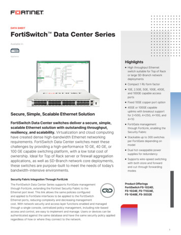
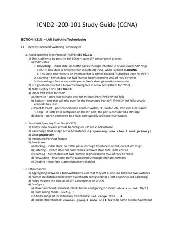
Multiple Spanning Tree Protocol (MSTP)Multiple Spanning Tree Protocol (MSTP)Conceptually, MSTP views the total bridged network as one that comprises a number ofMultiple Spanning Tree Regions (MSTRs), where each region can contain up to 64 spanningtrees, which operate locally, called Multiple Spanning Tree Instances (MSTIs). AlliedWaresupports up to 15 MSTIs. The regions are linked by the Common Internal Spanning Tree(CIST).MSTP uses BPDUs to exchange information between spanning-tree compatible devices, toprevent loops in each MSTI and also in the CIST, by selecting active and blocked paths. Thisprocess is described in Table 1 on page 4.Advantage ofMSTP overRSTPMSTP is similar to RSTP, in that it provides loop resolution and rapid convergence. However,RSTP can keep track of only one spanning-tree. MSTP can track many spanning-trees,referred to as instances. MSTP makes it possible to have different forwarding paths fordifferent MST instances. This enables load balancing of network traffic across redundant links,so that all the links in a network can be used by at least one MSTI, and no link is leftcompletely idle. That is to say that no link is unnecessarily shut down by spanning-tree.Essentially, MSTP is VLAN aware and RSTP is not VLAN aware. MSTP BPDUs and RSTPBPDUs are compatible, so a network can have a mixture of MSTP and RSTP areas.Multiple Spanning Tree Instances (MSTI)MSTP enables the grouping and mapping of VLANs to different spanning tree instances. So,an MST Instance (MSTI) is a particular set of VLANs that are all using the same spanning tree.In a network where all VLANs span all links of the network, judicious choice of bridgepriorities for different MSTIs can result in different switches becoming root bridges fordifferent MSTIs. That will result in the different MSTIs choosing different active topologies onthe network. An example of how different MSTIs can choose different active topologies onthe same physical set of links is illustrated in Figure 1 on page 12.MSTP is compatible with RSTP and STP—see "Common and Internal Spanning Tree(CIST)" on page 14.Spanning Tree Protocols: STP, RSTP, and MSTP Page 11
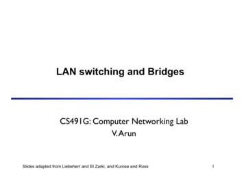
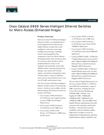
Multiple Spanning Tree Protocol (MSTP)Figure 1: Different spanning trees created by different MSTIs on the same physical layoutRoot bridge forMSTI 3Root bridge forMSTI 1Root bridge forMSTI 2Physical connectionsSpanning tree of MSTI 1 containing vlans 2, 7, 9, 43Spanning tree of MSTI 2 containing vlans 16, 18, 24, 40Spanning tree of MSTI 3 containing vlans 23, 39, 50, 112Diff MSTI 1MSTP regionsAn MST region is a set of interconnected switches that all have the same values for thefollowing MST configuration identification elements: MST configuration name - the name of the MST region Revision level - the revision number of configuration Configuration digest - the mapping of which VLANs are mapped to which MST instancesEach of the MST instances created are identified by an MSTI number. This number is locallysignificant within the MST region. Therefore, an MSTI will not span across MST regions.Page 12 Spanning Tree Protocols: STP, RSTP, and MSTP
Multiple Spanning Tree Protocol (MSTP)Figure 2: MSTIs in different regionsRegion 1Physical connectionsMSTI1MSTI2MSTI3Region 3MSTI1MSTI3Region 2MSTI2MSTI4The MSTI1 in Region 1 is unrelated to the MSTI1 in Region 3. Similarly, the MSTI2 in Region 1 is quiteunrelated to the MSTI2 in Region 2.MSTI numbersThe task of assigning each bridge to a particular region is achieved by the member bridgeseach comparing their MST Configuration Identifiers. More information on configurationidentifiers is provided in Table 6, but for the moment an MST Configuration Identifier cansimply be thought of as an identifier that represents the mapping of VLANs to MSTIs withineach bridge. Therefore, bridges with identical MST Configuration Identifiers, must haveidentical MSTI mapping tables.While each MSTI can have multiple VLANs, each VLAN can be associated with only oneMSTI. Once these associations have been made, the bridges in each region can transmit theirspanning tree BPDUs and advertise their MSTIs. This in turn establishes the active data pathsbetween the bridges for each group of VLANs (that is, for each MSTI) and block anyduplicate paths within each instance. A particular advantage of this enhancement applieswhere a large number of VLANs share a few internetwork paths. In this situation there needonly be as many Multiple Spanning Tree Instances (MSTIs) as there are source anddestination bridge pairs, remembering that a pair of bridges probably has multiple pathsbetween them.In order to ensure that each bridge within a region maintains the same configurationinformation (particularly their VID to MSTI mappings) and to ensure each bridge’smembership of a particular region, the bridges exchange configuration information in theSpanning Tree Protocols: STP, RSTP, and MSTP Page 13
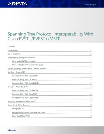
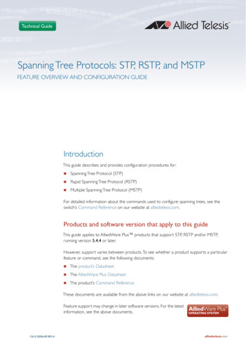
Multiple Spanning Tree Protocol (MSTP)form of MST Configuration Identifiers. Table 6 below, provides a breakdown of an MSTConfiguration Identifier. A detailed explanation of bridge configuration identifiers can befound in Section 13.7 of the IEEE 802.1Q-2003 standard.Table 6: MST Configuration IdentifierFIELD NAMEDESCRIPTIONFormat SelectorA single octet field whose value of 0 indicates MSTP operationRegion NameA name (up to 32 characters long) that identifies a particular MST region,defined using the region command.Revision LevelA number representing the region’s revision level, defined using therevision command.Configuration DigestA 16 octet (HMAC-MD5 based) signature created from the MSTconfiguration tableCommon and Internal Spanning Tree (CIST)The CIST is the default spanning tree instance of MSTP, i.e. all VLANs that are not membersof particular MSTIs are members of the CIST. Also, an individual MST region can be regardedas a single virtual bridge by other MST regions. The spanning tree that runs between regionsis the CIST. The CIST is also the spanning tree that runs between MST regions and SingleSpanning Tree (SST) entities. In Figure 3, the STP that is running between the regions, and tothe SST bridges, is the CIST.Figure 3: The CIST operates on links between regions and to SST devicesMSTPRegion 1MSTPRegion 3The three switches shownare non-MSTP capableMSTPRegion 2RSTP operates on these linksMSTP vs RSTPPage 14 Spanning Tree Protocols: STP, RSTP, and MSTP
Multiple Spanning Tree Protocol (MSTP)In common with legacy spanning tree systems, the CIST protocol first determines its rootbridge from all the bridges on the network. This is the bridge that contains the lowest bridgeidentifier. The protocol then selects a regional root bridge for each MSTR. This is the bridgethat provides the best path to the CIST root. After the MSTR root bridges have beenchosen, they then act on the region’s behalf in such a way that the region appears to theCommon Spanning Tree (CST) as a virtual bridge. So in addition to having multiple MSTIs,each region operates as a bridge in a CST.CISTIn addition to the individual MSTIs within each MSTP region, the MSTP region is a member ofa network-wide spanning tree called the Common and Internal Spanning Tree (CIST).Conceptually, each region represents a virtual bridge. Internal and external bridgeconnectivity are two independent functions.Frames with VIDs allocated to the CIST are subject to the rules and path costs of thecomplete bridged LAN as determined by the CIST’s vectors. Frames other than these aresubject
spanning tree algorithm itself is defined by the IEEE standard 802.1D and its later revisions. The IEEE Standard 802.1 uses the term bridge to define the spanning tree operation, and uses t