Transcription
HP/Cisco Switching and RoutingInteroperability CookbookMay 2011
HP/Cisco Interoperability Configuration CookbookTABLE OF CONTENTSIntroduction . 3Interoperability testing . 5Virtual LAN (VLAN) trunking . 7Jumbo frame switching . 10Jumbo frame routing . 14Link aggregation . 18Spanning tree case 1: RSTP/Rapid-PVST . 21Spanning tree case 2: MSTP/PVST . 25Spanning tree case 3: MSTP/Rapid-PVST . 30Spanning tree case 4: MSTP/MSTP . 34OSPFv2 (OSPF for IPv4). 39OSPFv3 (OSPF for IPv6). 44IP multicast switching . 48IP multicast routing . 50Virtual router redundancy protocol (VRRP) interoperability . 56Appendix A: About Network Test . 60Appendix B: Sample Configuration Files . 60Appendix C: Software Releases Tested . 60Appendix D: Disclaimer . 60ILLUSTRATIONSPage2Figure 1: HP-Cisco interoperability test bed . 6Figure 2: Jumbo frame switching test bed. 12Figure 3: Jumbo frame routing test bed . 15Figure 4: Link aggregation test bed. 19Figure 5: Virtual router redundancy protocol test bed . 57Version 2011050900. Copyright 2011 Network Test Inc. All rights reserved.
HP/Cisco Interoperability Configuration CookbookIntroductionObjectiveThis configuration guide aims to help networking professionals interconnect HP Networking andCisco Catalyst switches using a variety of protocols commonly found in enterprise campusnetworks. By following the step-by-step procedures described in this document, it should bepossible to verify interoperability and to pass traffic between the two vendors’ switches.Intended audienceThis guide is intended for any network architect, administrator, or engineer who needs tointerconnect HP and Cisco Ethernet switches.This guide assumes familiarity with basic Ethernet and TCP/IP networking concepts, as well asat least limited experience with the HP Networking and Cisco IOS command-line interfaces(CLIs). No previous experience is assumed for the protocols discussed in this document.For basic TCP/IP networking concepts, the standard references are Internetworking withTCP/IP, Volume 1 by Douglas E. Comer and TCP/IP Illustrated, Volume 1 by W. Richard Stevens.For IP multicast topics, Deploying IP Multicast in the Enterprise by Thomas A. Maufer is apopular choice.Devices under testUsing the commands given in this document, Network Test has verified interoperabilitybetween the HP A9505, HP E5406zl, and HP A5800 Ethernet switches and Cisco Catalyst 6509,Cisco Catalyst 4506, and Catalyst 3750-E Ethernet switches. Appendix B lists software versionsused.Page3Except where specifically noted, command syntax for HP Networking and Cisco Catalystswitches does not change across product lines. In cases where HP A-series and E-series switchesuse different command syntax, this is explicitly noted.
HP/Cisco Interoperability Configuration CookbookConventions used in this documentThe following table lists text and syntax conventions.ConventionsDescriptionExamplesBold TypeRepresents user-inputted text.To enter configuration mode, type thesystem-view command:Fixed-width text likethisRepresents output that appears onthe terminal screen. HP5800 system-view A9505 display stp bridgeMSTIDPortRole STP OOT0GigabitEthernet3/0/11DESI FORWARDINGNONE0GigabitEthernet3/0/16DESI FORWARDINGNONEPage4Italic text like this Introduces important newterms Identifies book titles Identifies RFC and Internetdraft titles A policy term is a named structurethat defines match conditions andactions. TCP/IP Illustrated Volume 1 by W.Richard Stevens. RFC 4814, Hash and Stuffing:Overlooked Factors in NetworkDevice Benchmarking
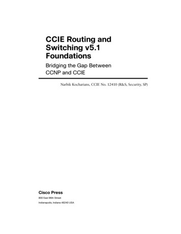
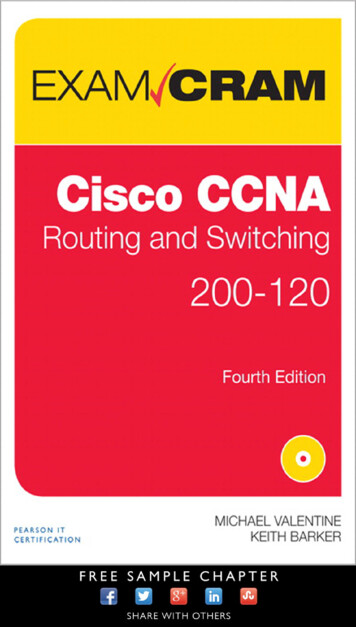
HP/Cisco Interoperability Configuration CookbookInteroperability testingFor each protocol tested, this document uses a five-section format consisting of objective,technical background, HP configuration, Cisco configuration, and test validation.TopologyExcept where otherwise noted, engineers used the standard test bed shown in Figure 1 belowto validate protocol interoperability. The test bed uses the three-tier network design commonlyfound in campus enterprise networks, with access, distribution, and core layers represented. Inthis example network, access switches (HP A5800 and Cisco Catalyst C3750-E) connect todistribution switches (HP E5406zl and Cisco Catalyst 4506), which in turn connect to coreswitches (HP A9505 and Cisco Catalyst 6509). For redundancy, multiple connections existbetween switch layers.Page5Test engineers configured link aggregation between HP A5800 and HP E5406zl switches;between HP E5406zl and HP A9505 switches; between HP A9505 and Cisco Catalyst 6509switches; between Cisco Catalyst 6509 and Cisco Catalyst 4506 switches; and between CiscoCatalyst 4506 and Cisco Catalyst 3750-E switches. The use of link aggregation is not mandatory,however.
HP/Cisco Interoperability Configuration CookbookH3C S9505EE S RES0RUNALMCF OLEETRESDISK 0PORT 1RXCATALYST 6500 SUPERVISOR ENGINE 32USB 2.0PORT 2TXRXTXPORT 3132Core 748 PORT GIGABIT ETHERNET SFPSTATUS1110 GbE10 TATUSPWR1This device has more than one powerinput. DO disconnect all power inputsto power off this device.ON19OFF1POEON2PWR2High leakage current,earthconnection essential beforeconnecting power supply.OFF2POWER 1: 100-240V;50/60Hz;16APOWER 2: 100-240V;50/60Hz;16APOWER 1UPPOWER 2INPUT100-240 V 16 A60/50 HzALSTINHP A9505GbELNRUINPUTOKFANOKOUTPUTFAILPower Supply 1Power Supply 2Catalyst 6500 SERIESCisco Catalyst 6509GbESWITCHED SHOULD BE IN THE OFF ‘O’ POSITION TO INSTALL /REMOVE POWER SUPPLIES. FASTENERS MUST BE FULLY ENGAGEDPRIOR TO OPERATING POWER SUPPLY100-240V 12A50/60HzOUTPUT FAILPOE ENABLEDFAN OKINPUT 1OKINPUT 2OK100-240V l5406zlJ9447AWS-X4516 SUPERVISOR ENGINE VSUPERVISOR1Catalyst4506-EJ8699AUPLINK 1CONSOLEUPLINK 2ACTIVELINKProCurve NetworkingACTIVEACTIVE1%StatusProCurve Switch 5400zlManagement ModuleJ8726AInnovationHP ProCurve HPNetworkingUsezl Mgmt FlashTempChas DIMMFan3412InternalPowerG HActModulesPoEPwrFDxPoESpdUsrConsoleLED ModeAuxiliary 23A11335522446677991111131315 1517 1719 19212123238810101212141416 1618 1820 2022222424BUse onlyHP ProCurveSFPsWS-X4302-GB2ProCurveProCurveGig-TPoE 24p Gig-Tzl Module1000 BASE-XSWITCHING MODULESTATUS12zl 2222zlzl2424PoE-IntegratedPoE-Integrated 10/100/1000Base-T10/100/1000Base-T PortsPorts (1-24)(1-24)--PortsPortsareareAutoIEEEMDIXAuto e-T10/100/1000Base-TPortsPorts (1-24)(1-24) -- PortsPorts areare IEEEAuto AutoMDIXMDI/MDI-XPoE-IntegratedWS-X4302-GBC3ONE Services 516171819202212223242526DAvaya Aura TM SBCpowered by Acme Packet1000 BASE-XSWITCHING MODULE2728293031323334353637383940414243444546ONE Services ModuleAvaya Aura TM SBCpowered by Acme PacketPCIe 14748PCIe 1PCIe 2Distribution layerPCIe 24EMAX 3141516151648-PORT10/100/1000 BASE TIN-LINE POWER 323132MULTI-SPEEDGIGABIT ETHERNETSWITCHING MODULE 7282930313233343536373839404142434445464748HP ONEExt Svcszl ctivityNetworkActivityUSBShutdownHP ONEExt Svcszl ModuleJ9543AzlmoduleMAX 15.4W/PORTSTATUSFANSTATUS348-PORT10/100/1000 BASE TIN-LINE POWER 17181928MULTI-SPEEDGIGABIT ETHERNETSWITCHING MODULE 33343544GbE6HP E5406zlCisco Catalyst 15161718192021222324Speed:Green 1000Mbps, Yellow 10/100Mbps23XSYSTRPSMASTERSTAT12523456Duplex: Green Full Duplex, Yellow Half Duplex78910111213141718192021222324H3C S580027262728ConsoleGreen 10Gbps, Yellow 1GbpsUnitModeGreen SpeedY ellow Duplex2824XSYSRPS1SLOTCatalyst 3750-E Series-24CiscoCatalyst 3750-E10/100/1000Base-TGbEGbESpirent TestCenterFigure 1: HP-Cisco interoperability test bed61625X2-2SPEEDSTACKPage1526X2-1DUPLXMODESFP HP A5800SeriesAccess layer
HP/Cisco Interoperability Configuration CookbookVirtual LAN (VLAN) trunkingObjectiveTo verify interoperability of IEEE 802.1Q VLAN trunking between HP Networking and CiscoCatalyst switches using tagged traffic.To verify interoperability of IEEE 802.1Q VLAN trunking between HP Networking and CiscoCatalyst switches using untagged traffic.BackgroundThe IEEE 802.1Q specification defines a method of defining virtual broadcast domains. A 4-byteVLAN header, usually called a “tag,” allows definition of broadcast domains that may differfrom physical switch topology. With VLANs, all switch ports are members of the same broadcastdomain; with VLAN tagging, a network manager can set up multiple broadcast domains acrossswitches, and restrict broadcasts for different VLANs on different ports.TopologyThis configuration example will validate VLAN trunking interoperability between HP Networkingand Cisco Catalyst switches in three ways: The switches will forward allowed tagged traffic from multiple VLANs across a trunkport. The switches will forward allowed untagged traffic from a native VLAN across a trunkport. The switch will not forward disallowed tagged traffic across a trunk port.PageThis test used the standard test bed (see Figure 1, above). In this example, all interswitchcommunication is done via VLAN trunks. The trunk ports on each switch will allow tagged trafficwith VLAN IDs from 301 through 303, and untagged traffic from ports with VLAN ID of 300. Afifth VLAN, with an ID of 304, is also defined by the trunk ports are configured not to allow thattraffic.7The final example above is a negative test to verify that switches with VLAN trunking willforward only traffic explicitly permitted by the switch configurations.
HP/Cisco Interoperability Configuration CookbookHP A-series commandsFirst, define VLANs 300 to 304. HP5800 system-view[HP5800] vlan 300 to 304Then, define a VLAN trunk port that allows tagged traffic from VLANs 301-303, and nativeuntagged traffic on VLAN 300.[HP5800] interface ] port link-mode bridge[HP5800-gigabitethernet1/0/23] port link-type trunk[HP5800-gigabitethernet1/0/23] undo port trunk permit vlan 1[HP5800-gigabitethernet1/0/23] port trunk permit vlan 300 to 303[HP5800-gigabitethernet1/0/23] port trunk pvid vlan 300[HP5800-gigabitethernet1/0/23] quitNext, define access-mode interfaces allowing untagged traffic for VLANs 300-304.[HP5800] interface GigabitEthernet1/0/1[HP5800-Gigabitethernet1/0/1] port link-mode bridge[HP5800-Gigabitethernet1/0/1] port access vlan 300[HP5800-Gigabitethernet1/0/1] interface GigabitEthernet1/0/2[HP5800-Gigabitethernet1/0/2] port link-mode bridge[HP5800-Gigabitethernet1/0/2] port access vlan 301[HP5800-Gigabitethernet1/0/2] interface GigabitEthernet1/0/3[HP5800-Gigabitethernet1/0/3] port link-mode bridge[HP5800-Gigabitethernet1/0/3] port access vlan 302[HP5800-Gigabitethernet1/0/3] interface GigabitEthernet1/0/4[HP5800-Gigabitethernet1/0/4] port link-mode bridge[HP5800-Gigabitethernet1/0/4] port access vlan 303[HP5800-Gigabitethernet1/0/4] interface GigabitEthernet1/0/5[HP5800-Gigabitethernet1/0/5] port link-mode bridge[HP5800-Gigabitethernet1/0/5] port access vlan 304[HP5800-Gigabitethernet1/0/5] quit[HP5800] quitHP E-series commandsPage8HP E-series switches combine trunk creation, access ports, and VLAN assignment together intoa single VLAN construct. A port that is a member of a single VLAN carrying only untagged trafficis an access port (ports A1-A5 in this example). A port that is a member of multiple VLANs thatcarries both tagged and untagged traffic is a VLAN trunk port (ports A9-A10 in this example).Here we define VLANs 300-304 and assign ports to them.HP5406ZL# configureHP5406ZL(config)# (vlan-300)#HP5406ZL(vlan-300)#300name "VLAN300"untagged A1,A9-A10ip address 10.1.2.1 255.255.0.0exit
HP/Cisco Interoperability Configuration CookbookHP5406ZL(config)# vlan 301HP5406ZL(vlan-301)#name "VLAN301"HP5406ZL(vlan-301)#untagged A2HP5406ZL(vlan-301)#ip address 10.2.2.1HP5406ZL(vlan-301)#tagged A9-A10HP5406ZL(vlan-301)#exitHP5406ZL(config)# vlan 302HP5406ZL(vlan-302)#name "VLAN302"HP5406ZL(vlan-302)#untagged A3HP5406ZL(vlan-302)#ip address 10.3.2.1HP5406ZL(vlan-302)#tagged A9-A10HP5406ZL(vlan-302)#exitHP5406ZL(config)# vlan 303HP5406ZL(vlan-303)#name "VLAN303"HP5406ZL(vlan-303)#untagged A4HP5406ZL(vlan-303)#ip address 10.4.2.1HP5406ZL(vlan-303)#tagged A9-A10HP5406ZL(vlan-303)#exitHP5406ZL(config)# vlan 304HP5406ZL(vlan-304)#name "VLAN304"HP5406ZL(vlan-304)#untagged A5HP5406ZL(vlan-304)#ip address o commandsThe following commands apply to a Cisco Catalyst 6509. The syntax is similar for the Catalyst3750-E switches and Cisco Catalyst 4506 switches.First, define VLANs 300 to 304.Cat6509# configure terminalCat6509(config)# vlan 300-304Then, define a VLAN trunk port that allows tagged traffic from VLANs 301-303, and nativeuntagged traffic on 300.Cat6509(config)# interface GigabitEthernet4/9Cat6509(config-if)# switchportCat6509(config-if)# switchport trunk encapsulation dot1qCat6509(config-if)# switchport trunk native vlan 300Cat6509(config-if)# switchport trunk allowed vlan 300-303Cat6509(config-if)# switchport mode trunkCat6509(config-if)# exitPageCat6509(config)# interface GigabitEthernet6/0/1Cat6509(config-if)# switchport access vlan 300Cat6509(config-if)# switchport mode accessCat6509(config-if)# interface GigabitEthernet6/0/29Next, define access-mode interfaces allowing untagged traffic from VLANs 300-304.
HP/Cisco Interoperability Configuration CookbookCat6509(config-if)# switchport access vlan 301Cat6509(config-if)# switchport mode accessCat6509(config-if)# interface GigabitEthernet6/0/3Cat6509(config-if)# switchport access vlan 302Cat6509(config-if)# switchport mode accessCat6509(config-if)# interface GigabitEthernet6/0/4Cat6509(config-if)# switchport access vlan 303Cat6509(config-if)# switchport mode accessCat6509(config-if)# interface GigabitEthernet6/0/5Cat6509(config-if)# switchport access vlan 304Cat6509(config-if)# switchport mode accessCat6509(config-if)# endValidationThe Spirent TestCenter traffic generator/analyzer can be configured to offer traffic betweenpairs of access-mode interfaces on each switch. In all cases – involving unicast, multicast, orbroadcast traffic – traffic will stay local to the VLAN in which it is defined. For example, trafficoffered to VLAN 300 on the HP switches will be forwarded only to interfaces in VLAN 300 on theCisco switches and vice-versa.If desired, port mirroring can be enabled on either HP or Cisco switches to verify that the trunkports carry tagged traffic VLAN IDs 301-303 and untagged traffic for VLAN ID 300. As a finalverification that VLANs limit broadcast domains, Spirent TestCenter can be configured to offertraffic on access ports with VLAN 304. The trunk ports on all switches will not forward thistraffic.Jumbo frame switchingObjectiveTo validate the ability of HP Networking and Cisco Catalyst switches to correctly forwardbidirectional traffic consisting of jumbo frames.Page10BackgroundFor many years the IEEE Ethernet specification has defined the maximum length of an Ethernetframe to be 1,518 bytes (or 1,522 bytes with an 802.1Q VLAN tag). The use of jumbo frames –those larger than 1518 bytes – remains nonstandard. However, jumbo frames can improve theperformance of applications involving bulk data transfer, such as backup and disaster recovery.
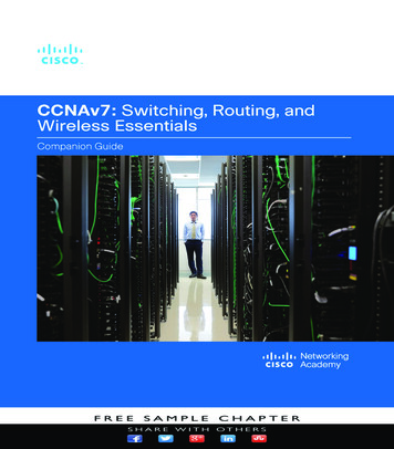
HP/Cisco Interoperability Configuration CookbookHP and Cisco switches both support 9,216-byte jumbo frames, including Ethernet CRC. Thissection explains how to configure both vendors’ switches to exchange jumbo frames.TopologyIn this example, the Spirent TestCenter traffic generator offers 9,216-byte jumbo Ethernetframes using a “partially meshed” topology, meaning all traffic offered to ports on HP switchesare destined to ports on Cisco switches and visa-versa. VLAN trunk ports connect the switchesand VLAN access ports at the edge accept untagged jumbo frames. However, the ability toswitch jumbo frames does not depend on VLAN tagging. This example would also work with allinterfaces passing untagged traffic.Page11Figure 2 below illustrates the configuration used to validate jumbo frame switching. This testdeviates from the standard test bed by the removal of the link aggregation trunks between theCisco Catalyst 4506 and the Cisco Catalyst 3750-E as well as the link aggregation trunk betweenthe Cisco Catalyst 4506 and the Cisco Catalyst 6509. There is also no connection between theCisco Catalyst 4506 and the Cisco Catalyst 6509. As noted in the configuration sections below,all interfaces explicitly support switching of jumbo frames. Engineers configured all interswitchtrunks to use VLAN trunking, in this case carrying traffic from VLAN 300.
HP/Cisco Interoperability Configuration CookbookH3C S9505EE S RES0RUNALMCF OLEETRESDISK 0PORT 1RXCATALYST 6500 SUPERVISOR ENGINE 32USB 2.0PORT 2TXRXTXPORT 3132Core 748 PORT GIGABIT ETHERNET SFPSTATUS1110 GbE10 TATUSPWR1This device has more than one powerinput. DO disconnect all power inputsto power off this device.ON19OFF1POEON2PWR2High leakage current,earthconnection essential beforeconnecting power supply.OFF2POWER 1: 100-240V;50/60Hz;16APOWER 2: 100-240V;50/60Hz;16APOWER 1UPPOWER 2INPUT100-240 V 16 A60/50 HzALSTINHP A9505GbELNRUINPUTOKFANOKOUTPUTFAILPower Supply 1Power Supply 2Catalyst 6500 SERIESCisco Catalyst 6509GbESWITCHED SHOULD BE IN THE OFF ‘O’ POSITION TO INSTALL /REMOVE POWER SUPPLIES. FASTENERS MUST BE FULLY ENGAGEDPRIOR TO OPERATING POWER SUPPLY100-240V 12A50/60HzOUTPUT FAILPOE ENABLEDFAN OKINPUT 1OKINPUT 2OK100-240V l5406zlJ9447AWS-X4516 SUPERVISOR ENGINE VSUPERVISOR1Catalyst4506-EJ8699AUPLINK 1CONSOLEUPLINK 2ACTIVELINKProCurve NetworkingACTIVEACTIVE1%StatusProCurve Switch 5400zlManagement ModuleJ8726AInnovationHP ProCurve HPNetworkingUsezl Mgmt FlashTempChas DIMMFan3412InternalPowerG HActModulesPoEPwrFDxPoESpdUsrConsoleLED ModeAuxiliary 23A11335522446677991111131315 1517 1719 19212123238810101212141416 1618 1820 2022222424BUse onlyHP ProCurveSFPsWS-X4302-GB2ProCurveProCurveGig-TPoE 24p Gig-Tzl Module1000 BASE-XSWITCHING MODULESTATUS12zl 2222zlzl2424PoE-IntegratedPoE-Integrated 10/100/1000Base-T10/100/1000Base-T PortsPorts (1-24)(1-24)--PortsPortsareareAutoIEEEMDIXAuto e-T10/100/1000Base-TPortsPorts (1-24)(1-24) -- PortsPorts areare IEEEAuto AutoMDIXMDI/MDI-XPoE-IntegratedWS-X4302-GBC3ONE Services 516171819202212223242526DAvaya Aura TM SBCpowered by Acme Packet1000 BASE-XSWITCHING MODULE2728293031323334353637383940414243444546ONE Services ModuleAvaya Aura TM SBCpowered by Acme PacketPCIe 14748PCIe 1PCIe 2Distribution layerPCIe 24EMAX 3141516151648-PORT10/100/1000 BASE TIN-LINE POWER 323132MULTI-SPEEDGIGABIT ETHERNETSWITCHING MODULE 7282930313233343536373839404142434445464748HP ONEExt Svcszl ctivityNetworkActivityUSBShutdownHP ONEExt Svcszl ModuleJ9543AzlmoduleMAX 15.4W/PORTSTATUSFANSTATUS348-PORT10/100/1000 BASE TIN-LINE POWER 17181928MULTI-SPEEDGIGABIT ETHERNETSWITCHING MODULE 33343544GbE6HP E5406zlCisco Catalyst 6171819202122GbE2324Speed:Green 1000Mbps, Yellow 10/100Mbps23XSYSTRPSMASTERSTAT12523456Duplex: Green Full Duplex, Yellow Half Duplex78910111213141516171819202122232426H3C S5800X2-1DUPLX2527262728ConsoleX2-2Green 10Gbps, Yellow 1GbpsSPEEDSTACKMODEUnitCiscoCatalyst 3750-EModeGreen SpeedY ellow Duplex2824XSYSRPS1SLOTCatalyst 3750-E Series-2410/100/1000Base-TGbEGbESFP SeriesAccess layerHP A5800Spirent TestCenterFigure 2: Jumbo frame switching test bedHP A-series commandsHP A-series switches have jumbo frames enabled by default. The following commands are usedto explicitly set the maximum transmission unit (MTU). The MTU is set in the interfaceconfiguration context.Page12 HP5800 system-view[HP5800] interface GigabitEthernet1/0/1[HP5800-Gigabitethernet1/0/1] port link-mode bridge[HP5800-Gigabitethernet1/0/1] jumboframe enable 9216[HP5800-Gigabitethernet1/0/1] quit[HP5800] quit
HP/Cisco Interoperability Configuration CookbookHP E-series commandsHP E-series switches set the MTU on a per-VLAN basis. When enabled, all ports on that VLANwill forward jumbo frames.HP5406ZL# configureHP5406ZL(config)# P5406ZL(config)#300name "VLAN306"untagged A1-A5,A9-A10,Trk1-Trk2ip address 10.1.2.1 255.255.0.0jumboexitexitCisco commandsOn Cisco Catalyst 6509 and Cisco Catalyst 4506 switches, jumbo frame support varies by linecard. For line cards that support jumbo frames, MTU is set on a per-interface basis.Cat6509# configure terminalCat6509(config)# interface GigabitEthernet4/48Cat6509(config-if)# switchportCat6509(config-if)# switchport access vlan 300Cat6509(config-if)# switchport mode accessCat6509(config-if)# mtu 9216Cat6509(config-if)# endOn Cisco Catalyst 3750-E switches, MTU is set systemwide:Cat3750E# configure terminalCat3750E(config)# system mtu jumbo 9216Cat3750E(config)# endValidationPage13Generating jumbo frames between the attached clients and servers will validate the ability ofthe switches to exchange jumbo traffic. All switches will forward all jumbo frames with zeroframe loss.
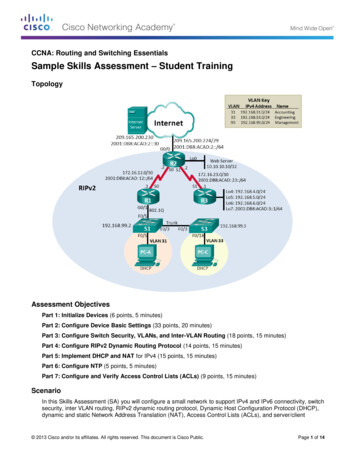
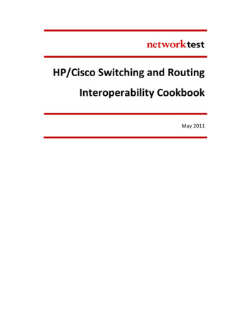
HP/Cisco Interoperability Configuration CookbookJumbo frame routingObjectiveTo validate the ability of HP Networking and Cisco Catalyst switches to correctly routebidirectional traffic consisting of jumbo frames.BackgroundSome routing protocols, such as open shortest path first (OSPF), require that both routers usethe same MTU before exchanging routing information. For Ethernet interfaces, the requirementfor matched MTUs applies equally to jumbo frames (those larger than 1518 bytes) as tostandard-length frames.HP Networking and Cisco Catalyst switches both support 9,216-byte jumbo frames, includingEthernet CRC. This section explains how to configure both vendors’ devices to set up on anOSPF routing session using jumbo frames.TopologyIn this example, the HP A9505, HP E5406zl, and HP A5800 switches are configured as OSPFrouters exchanging jumbo frames with Cisco Catalyst 6509, Cisco Catalyst 4506, and CiscoCatalyst 3750-E switches.Page14Figure 3 below illustrates the configuration used to validate jumbo frame routing. This testdeviates from the standard test bed by the removal of the link aggregation trunks between theCisco Catalyst 4506 and the Cisco Catalyst 3750-E, and between the Cisco Catalyst 4506 and theCisco Catalyst 6509. There is also no connection between the Cisco Catalyst 4506 and the CiscoCatalyst 6509. In addition, all devices routed traffic at layer 3 in this test. In this example, OSPFrouting sessions are established between all connected devices.
HP/Cisco Interoperability Configuration CookbookH3C S9505EE S RES0RUNALMCF OLEETRESDISK 0PORT 1RXCATALYST 6500 SUPERVISOR ENGINE 32USB 2.0PORT 2TXRXTXPORT 3132Core 748 PORT GIGABIT ETHERNET SFPSTATUS1110 GbE10 TATUSPWR1This device has more than one powerinput. DO disconnect all power inputsto power off this device.ON19OFF1POEON2PWR2High leakage current,earthconnection essential beforeconnecting power supply.OFF2POWER 1: 100-240V;50/60Hz;16APOWER 2: 100-240V;50/60Hz;16APOWER 1UPPOWER 2INPUT100-240 V 16 A60/50 HzALSTINHP A9505GbELNRUINPUTOKFANOKOUTPUTFAILPower Supply 1Power Supply 2Catalyst 6500 SERIESCisco Catalyst 6509GbESWITCHED SHOULD BE IN THE OFF ‘O’ POSITION TO INSTALL /REMOVE POWER SUPPLIES. FASTENERS MUST BE FULLY ENGAGEDPRIOR TO OPERATING POWER SUPPLY100-240V 12A50/60HzOUTPUT FAILPOE ENABLEDFAN OKINPUT 1OKINPUT 2OK100-240V l5406zlJ9447AWS-X4516 SUPERVISOR ENGINE VSUPERVISOR1Catalyst4506-EJ8699AUPLINK 1CONSOLEUPLINK 2ACTIVELINKProCurve NetworkingACTIVEACTIVE1%StatusProCurve Switch 5400zlManagement ModuleJ8726AInnovationHP ProCurve HPNetworkingUsezl Mgmt FlashTempChas DIMMFan3412InternalPowerG HActModulesPoEPwrFDxPoESpdUsrConsoleLED ModeAuxiliary USLINK100%1Locator35779
HP/Cisco Switching and Routing Interoperability Cookbook May 2011 . HP/Cisco Interoperability Configuration Cookbook e 2 . Identifies book titles Identifies RFC and Internet-draft titles A policy term is a named structure that defines match conditions and actions.