Transcription
Product CatalogueDESIGNED FOR PERFORMANCEwww.henrytech.com
GENERAL INFORMATIONThe information contained in this catalogue is correct at the timeof publication.WELCOME TO HENRY TECHNOLOGIESHenry Technologies has a policy of continuous productdevelopment; we therefore reserve the right to change technicalspecifications without prior notice.Extensive changes within our industry have seen products ofHenry Technologies being used in a variety of new applications.We have a policy, where possible, to offer research anddevelopment assistance to our clients. We readily submit ourproducts for assessment at the development stage, to enableour clients to ascertain product suitability for a given designapplication.It remains the responsibility of the system designer to ensure allproducts used in the system are suitable for the application.For details of our warranty cover, please refer to our standardterms and conditions of sale. Copies are available on ourwebsite.Date of publication: APRIL 2016WWW.HENRYTECH.COM
CONTENTSPRODUCT CATALOGUEE1Introduction 2Manufacturing & Quality 3Engineering & Product 4Safety DevicesFittingsBall Valves5Pressure Relief Valves56Copper Fittings107Check Valves8Pressure Relief Valves -X Series58Copper Couplings109Magnetic Check Valves12Pressure Relief Valves -Transcritical CO260Copper Bushes OD to ID110Expansion Valves14Rupture Discs62Copper Tees & Elbows111Flange Unions15Three Way Dual Shut Off Valves64Copper Elbows & Return Bends112Packed Shut Off Valves17Pressure Indicator65Copper Elbows, Bonnets & Y Pieces113Packed Line Valves21Sentry Safety Device Assemblies66Copper Stop Ends & Washers114Industrial Shut Off Valves23Safety Device Kits68Pipe Clips115Rotalock Valves24Brass Fittings116Rotalock Connectors28Flare Nuts117Capped Line Valves29Schrader Fittings118Service Valves32Brass Fittings120Solenoid Valves34Unions121Solenoid Coils36Forged Elbows126Reversing Valves38Forged Tees128Flow Switches39Moisture Indicators40Rotalock Sight Glasses43Sight Glasses46Liquid Indicators47Compressor Protection DevicesOil Mangagement Systems69Helical Oil Separators71Impingement Type Oil Separators75Coalescent Oil Separators78Electronic Oil Controls81Oil Reservoirs84Reservoir Pressure Valves86Oil Strainers87Controls130Oil Filters & Oil Filter Driers88Tools131Discharge Mufflers89Automotive132Vibration Eliminators91Controls & ToolsPressure VesselsLiquid Receivers48Suction Accumulators50Liquid ManagementTerms & ConditionsFilter Drier & Strainers93Total Filtration Management Solutions94Sealed Filter Driers95Sealed Burnout Filter Driers99Pancake Filter Driers101Bi Flow Filter Driers102Replaceable Core Filter Driers104133WELCOME TO HENRY TECHNOLOGIESFlow Controls1
INTRODUCTIONHenry Technologies GroupHenry Technologies is a leading global manufacturer and supplier of air conditioning& refrigeration products, with an emphasis on refrigeration components andstrengths in oil management controls and safety devices.Since 1914 Henry Technologies continues to lead in the design and fabricationof products for a wide range of commercial and industrial applications, offeringsuperior quality standards and technical leadership.Through the consolidation of the Henry, AC&R and Heldon brands, HenryTechnologies has one of the broadest component product portfolios in thecommercial refrigeration industry, including refrigerant and oil flow control products,safety valves and system components.With manufacturing facilities and operating subsidiaries in the USA, UK, Australia,China & Singapore, Henry Technologies markets its products globally to leadingOEM’s, wholesalers and contractors.WELCOME TO HENRY TECHNOLOGIESHenry Technologies’ ability to serve their customers on a global basis is enhancedby their regional manufacturing operations and extensive sales and customersupport.2WWW.HENRYTECH.COM
MANUFACTURING & QUALITYManufacturingHenry Technologies remains committed to manufacturing in Australia and continues to invest in equipment and training to providesolutions to local challenges. Our engineers and technicians support a skilled staff of trade qualified welders, toolmakers and fitter/turners. Henry Technologies has a proven track record in Australia, in the production of quality pressure vessels to the AS/NZSstandards, with customers across all areas of the HVAC&R industry.Our firm belief in Australian manufacturing will be further evidenced by our largest ever investment in equipment during 2016.Henry Technologies Pty Ltd is also supported by our other manufacturing locations in China, the UK and the USA. HenryTechnologies Holdings have just invested over 4 million USD in our China facilities together with our manufacturing partners inthe Hendricks portfolio of investments. State of the art cutting, welding, brazing, helium testing and powder coating equipment isnow used to produce the every-day products we sell to our markets worldwide.Our Glasgow, UK factory has invested in new high pressure impulse technology for trans-critical CO2 components, while our USAfactory continues to upgrade and re-invest in the factory in central Illinois.QualityHenry Technologies Pty Ltd is an ISO 9001 accredited company, we do not have the certification for the sake of a piece of paper,we live and breathe the tenets of the standard and it forms part of our commitment to our excellent quality record. We understandthat quality is a given for any customer and is not a luxury, we expect our products to perform to their design intent and to providetrouble free operation for our customers.Our welding and brazing procedures are independently tested and qualified by Welding Technology Institute of Australia certifiedwelding inspectors. The Henry Technologies Group worldwide enjoys an enviable reputation for quality and performance; we atHenry Technologies in Australia are committed to protecting our brand and the important brand names of our customers.WELCOME TO HENRY TECHNOLOGIESWe are proud that Henry Technologies continues a proud tradition of manufacturing, which spans a century and will continue toimprove and invest in line with our strategic long term goals.3
ENGINEERING & PRODUCTEngineeringHenry Technologies can boast over 75 years of engineering design experience in our Tullamarine facility, of which a combined40 years are in the HVAC&R industry. Our engineers work closely with our customers to provide solutions and help to improveoutcomes. Our products are “designed for performance” using the latest mathematical modelling and CAD software. Withinthe Henry group we have the following capabilities: Rapid prototypingComputer Flow Analysis (CFD)Finite Element AnalysisPressure vessel design software3D scanning3D PrintingOur engineers are also on hand to support technical questions from the industry and have representation or membership in allof the major industry organisations such as: AIRAH (Aus)AREMA (Aus)ASHRAE (USA)AHRI (USA)IIOR (International)IOR (UK)ProductOur products stand as testament to our philosophy as a company. The right materials, to the right dimensions, in the rightorder. Materials selection is the first point for all new products; it is the very foundation of our success. We offer one of thewidest ranges of refrigeration components in the market, crucial to providing our customers with a “one stop shop” experience.Once you buy something from Henry you realise that many of your purchasing challenges simply go away. We offer fully kittedproducts such as safety devices and charging assemblies, as well as your driers, sight-glasses, separators, accumulators,receivers, flexible hoses, vibration absorbers, pipe and fittings. We fit rotalock valves and full flow valves to receivers, as wellas liquid level probes and level sensors. We can even supply your fans and fan motors.WELCOME TO HENRY TECHNOLOGIESOur products are designed to provide the “best installed cost” for our customers, what does that mean? It doesn’t mean thecheapest purchase price; it means the least cost to get equipment up and running efficiently with no breakdowns and no callbacks.4WWW.HENRYTECH.COM
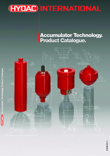
FLOW CONTROLSBall ValvesMaterials of ConstructionThe valve body, valve body adaptor, and seal cap are made from brass. Thestem is made from stainless steel. The pipe extensions are made from copper.The ball seals are made from virgin PTFE, stem O-rings and cap seal fromneoprene. The ball is made from electro-plated brass.Installation – Main IssuesThe valve body must be protected against excessive heat during installation,to prevent damage to the seals. Full instructions are given in the ProductInstruction Sheet included with each valve.Technical SpecificationAllowable Operating Temperature -40 C to 150 CAllowable Operating Pressure 0 to 4,800 kPag (0 to 700 psig)Sealing Integrity Features Premium quality PTFE ball seals.Double O-ring stem seal design.Premium quality neoprene stem O-ring sealsNeoprene cap seal (on new line)Features Bi-directional flow.Mounting pad for easy installation.Extended copper tails.Indicator on stem shows valve position – open or closed.Fully opened or closed with a quarter turn of the valve stem.Positive stem stop ensures precise positioning in the open orclosed position.Blow-out proof stem design.Double stem seal.Ball cavity vented to prevent over-pressure.Schrader Access options: 1/4” or 5/16”Integral Schrader access fitting on brass body.Full flow port design on Valves 3/8” to 3-1/8”.Body is hermetically sealed.Hexagonal seal cap with plastic tether included.Helium tested to a maximum of 4.69 E-7 cm3/sec.Benefits May be installed in any position.Can be mounted securely preventing undue stress on theconnecting pipe work.Allows for quick and easy installation.At a glance the valves position can be determined when cap is removed.Quick & simple operation gives the operator full control.Flow indicator arrow ensures the valve is in the position it is meant to bein – open or closed.Cannot blow out under pressure due to its design.Double O-Ring stem seal provides a greater sealing surface.Provides equalisation of pressure surrounding ball to ensuresmooth easy action. Allows for liquid expansion.Allow access to system pressure measurement.Schrader Access is positioned on the main body there is less chance ofdamage to the valve during installation.Full Flow means minimal pressure drop across the range ofvalves on offer.A streamlined design that is fully rated to 48 bar.Seal cap can be safely secured to valve body. TheNeoprene seal in the cap is the final defence in the Henry TripleStem Seal design.Helium leak tested: The smaller Helium molecule enables detection of minuteleaks that may not be detected by other leak testing methods.FLOW CONTROLSBall valves are used in a wide variety of air conditioning and refrigerationapplications. They can be used for both liquid and gas applications. Ballvalves are commonly used for isolating purposes. All ball valves aresuitable for HCFC and HFC refrigerants, along with their associated oils.The SWP of these valves allows them to be used for R410A andsub-critical CO2 applications.5
FLOW CONTROLSSCHRADERI.D.1/4” Schrader Access Port FittedDimensions (mm)Part No.Conn. Size ID(Inch)ABCMounting Hole SizeBall Port #8 -36 UNF1/23.70.339372041/21655410#8 -36 UNF1/26.00.339372055/81655413#8 -36 UNF1/212.00.339373063/41846716#8 -36 UNF3/418.10.629373077/81846719#8 -36 UNF3/426.10.649374091-1/82167623#10 - 32 UNF152.90.959375111-3/82359425#10 - 32 UNF1-1/473.51.529376131-5/8254109281/4 - 28 UNF1-1/2182.82.449376172-1/8289132341/4 - 28 UNF2245.74.58937721*2-5/8327132371/4 - 28 UNF2205.25.04937721FP2-5/8365154371/4 - 28 UNF2-1/2259.58.73937825FP3-1/8420178435/16-24 UNF3-1/8362.118.20* Reduced Port** Kv rating @ 1 bar pressure drop across valveI.D.No Access Port FittedDimensions (mm)Part No.Conn. Size IDFLOW CONTROLS(Inch)6MountingABCHole SizeBall 033/8165548#8 -36 UNF1/29072041/21655410#8 -36 UNF1/26.00.339072055/81655413#8 -36 UNF1/212.00.339073063/41846716#8 -36 UNF3/418.10.629073077/81846719#8 -36 UNF3/426.10.649074091-1/82167623#10 - 32 UNF152.90.959075111-3/82359425#10 - 32 UNF1-1/473.51.529076131-5/8254109281/4 - 28 UNF1-1/2182.82.449076172-1/8289132341/4 - 28 62.118.20** Kv rating @ 1 bar pressure drop across valveWWW.HENRYTECH.COM
FLOW CONTROLSSCHRADERI.D.5/16” Schrader Access Port FittedPart No.Dimensions (mm)Conn. Size IDMountingBall .33#8 -36 UNF3/418.10.6219#8 -36 UNF3/426.10.6423#10 - 32 UNF152.90.9525#10 - 32 UNF1-1/473.51.52Diameter(Inch)ABCHole Size9472033/8165548#8 -36 UNF1/29472041/21655410#8 -36 UNF9472055/81655413#8 -36 475111-3/823594(Inch)FLOW CONTROLS** Kv rating @ 1 bar pressure drop across valve7
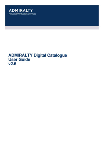
FLOW CONTROLSCheck ValvesCheck Valves are used in refrigeration and air-conditioning when the liquid orvapour refrigerant is required to flow in one direction only. The Check Valveallows for full flow in the direction of operational flow while preventing flow inthe opposite direction. A typical application would be to install a check valvedownstream of an oil separator. This prevents condensed liquid refrigerantfrom returning down the discharge line and into the oil separator.Please note that In-line Check Valves are not suitable for discharge linesof reciprocating compressors. This is due to the reciprocating compressorsdischarge pressure pulsations.The Henry Technologies range includes both the Lift type and the In-line typeCheck Valves.The Lift Check Valves are: 116, 205 & 2027 Series(Note: 205 Series is replacing the old 2024 Series)The In-line Check Valves are: 119 & 120 Series(Note: 119 & 120 Series is replacing the old 2001 & 2006 Series)Henry Technologies check valve are suitable for HCFC and HFC refrigerants,along with their associated oils. Typically, Henry Technologies Check Valveswill start to open at 3.4 kPa and be fully open at 34 kPa.FeaturesBenefits Flow direction arrow.Minimum opening pressure required.Designed for maximum flow and minimum pressure drop.Robust design.Optimised seat material.Models available with copper extensions – 120 Series.Working Temperature range: 116 & 205 Series -40 oC to 150 oC 119 & 120 Series -30 oC to 90 oC 2027 Series -40 oC to 100 oCInstallation – Main issuesManufacturing Standards Valves must be installed in accordance with the flow direction arrow. The valve bodies and valve internals must be protected against damageduring brazing. Full instructions are given in the Product InstructionSheet, included with each valve.Manufactured in accordance with AS/NZS 1677.2, CE & ULSafe Working Pressure 3,100 kPa / 205 Series 3,500 kPa / 116, 119 & 120 Series 4,200 kPa / 2027 Series Series 205 valves up to 1 3/8” connector size can be installed in anyposition except bonnet down. For larger sizes, the bonnet must bepositioned upwards. For all models, the recommended bonnet positionis upwards. Discharge check valves should be positioned as far from thecompressor as possible.FLOW CONTROLS8Ensures correct installation.Does not impose a load on the system.Negligible loss in system efficiency.Provides stable platform when mounted in a system.Efficient sealing with negligible leak rate.Quick and easy installation.Suitable for a wide range of applications.WWW.HENRYTECH.COM
FLOW CONTROLSConnectionPart No.Dimensions (mm)Size ID(Inch)KvWeightABCD(m3/Hr)(kg)CE 248.62.00SEPSEP205-1-3/81-3/8137321082511.92.74Cat ICat I205-1-5/81-5/8165381292915.44.23** 216511573825.57.76Cat I205-2-5/82-5/8279571834342.312.44Cat I** Designed for Heat Reclaim BypassConn. SizeR404AStyle(Inch)Liquid Lines (kW)Suction Vapour (kW)Hot Gas (m3/hr)62.9205-7/87/8Globe, Bolted Bonnet29.51.8205-1-1/81-1/8Globe, Bolted Bonnet42.33.587.2205-1-3/81-3/8Globe, Bolted Bonnet57.37.0121.6205-1-5/81-5/8Globe, Bolted Bonnet74.211.6157.3205-1-5/8-151-5/8Globe, Bolted Bonnet74.211.6157.3205-2-1/82-1/8Globe, Bolted Bonnet122.732.0260.1205-2-5/82-5/8Globe, Bolted Bonnet204.088.3432.11160077/8Y Type Screwed Bonnet47.14.8100.0Dimensions (mm)ConnectionPart No.Size .722.43.10.93CE CatSEPFLOW CONTROLSPart No.9
FLOW CONTROLS119 SeriesC/HexStraight Through DesignPart No.Dimensions (mm)ConnectionWeightSizeABC/Hex(kg)119-3/83/8 FL63.8-210.12119-1/21/2 FL76.2-320.13120-3/83/8 ID133.47.9210.13120-5/85/8 ID159.512.7320.29120 SeriesAngle Female SolderConnectionPart No.FLOW CONTROLSHENRY10WWW.HENRYTECH.COMSize ID(Inch)2027-14147/8Dimensions (mm)KvWeightABC(m3/Hr)(kg)9647408.950.82
FLOW CONTROLS1 2 0 S E RI E S205 SERIES1 Inlet ODS2 Outlet ODSPart NoConn Size (inch)205-7/8205-1 1/8205-1 3/8-CE205-1 5/8-CE205-2 1/8-CE205-2 5/8-CE7/8 ODS1 1/8 ODS1 3/8 ODS1 5/8 ODS2 1/8 ODS2 5/8 ODSPart NoConn Size (inch)NRV14NRV18NRV22-CENRV26-CE7/8 ODS1 1/8 ODS1 3/8 ODS1 5/8 ODSPart NoConn Size (inch)NRV14ENRV18ENRV22E-CENRV26E-CE7/8 ODS1 1/8 ODS1 3/8 ODS1 5/8 ODSDimensions 279D192425293843Weight (kg)Kv (m3/hr)CE 31.57SEPSEPCat ICat ICat ICat IA7878106106B20202727Dimensions (mm)C7070102102D38385757E11111717Weight (kg)Kv (m3/hr)CE Cat0.600.531.301.2058.513.516SEPSEPCat ICat IA7878106106B20202727Dimensions (mm)C191225264270D98116138138E19232528Weight (kg)Kv (m3/hr)CE Cat0.770.791.701.605.08.513.516.0SEPSEPCat ICat IInstallation – Main issues1. Valves must be installed in accordance with the flow direction arrow.2. The valve bodies and valve internals must be protected againstdamage during brazing. Full instructions are given in the ProductInstruction Sheet, included with each valve.3. Series 116 valves can be installed in any position except bonnetdown. This is the same for 205 series up to 1 3/8” size. For largersizes, the bonnet must be positioned upwards. The bonnet of theNRV series should be positioned upwards. For all models, therecommended bonnet position is upwards.4. Discharge check valves should be positioned as far from thecompressor as possible.FLOW CONTROLSNRV E SERIESNRV S E RI E S11
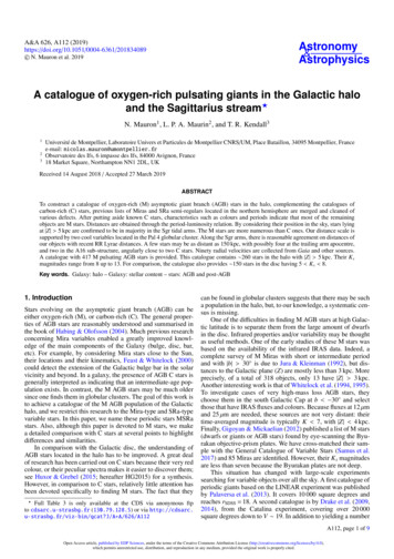
FLOW CONTROLSMagnetic Check ValvesThe Henry Technologies check valve uses magnetic attraction to return the valve plate to its seat rather than spring pressure. A conventional type check valverequires an increase in pressure to force the valve plate off its seat leading to an increase in pressure drop. The magnetic check valve (MCV) has a decreasingforce to move it away from its seat. The further it travels the magnetic attraction diminishes leading to a decrease in pressure drop. MCV’s are therefore a moreefficient option to the conventional check valves.The Henry MCV uses the latest technology in Dura Form processing, a manufacturing method that eliminates the use of braze materials that can overheat anddamage internal components. The body is 100% copper that has been spun into shape and the connections machined. The result is a valve that is hermeticallysealed, can easily be installed with either soft or hard solder, with a near zero leak rate and exceptional performance.Suitable for use in the Liquid, Suction, Discharge or Hot Gas lines employing fluorinated refrigerants, these valves are ideal in a new installation or as areplacement for conventional check valves.MCV’s are not recommended for Heat Reclaim applications with high differential pressures.FeaturesBenefits Designed for maximum flow and minimal pressure drop.Hermetically sealed copper body.Optimised seat material with a Neoprene coated valve plate.Multi orientation while maintaining flow direction.Built in 30 mesh strainer.Working Temperature range 40 oC to 150 oC.Safe Working Pressure 5,200 kPa up to 5/8” sizes. FLOW CONTROLSManufacturing StandardsManufactured in accordance with AS/NZS 1677.2Safe Working Pressure: Please refer to table on next page for details.12WWW.HENRYTECH.COMNegligible loss in system efficiency.Stable platform with no chance of a leak.Efficient sealing with a negligible leak rate.Able to be installed in any position.Strain debris out of the system and extend the valve service life.Suitable for a wide range of applications, includingcombination (muffler/check valve).Compatible with all fluorinated refrigerants and oils.
FLOW CONTROLSDimensionsPart No.ConnectionSizeADescriptionValve Length(mm)BValve 23301053.54CapacitiesSuction (kW)Liquid (kW)R22R134aR404AR22R134aR404ASWP(kPa 45.2106.7128.11,305.91,200927.34,48064.76FLOW CONTROLSThe rated liquid and suction capacities are based on an evaporating temperature: An average temperature of te -10oC, liquidtemperature ahead of the valve t 25oC and a pressure drop across the valve of p 15 kPa (2.18 psi).13
FLOW CONTROLSExpansion ValvesThe function of an Expansion Valve is to meter liquid refrigerantand induce a large pressure drop causing the refrigerant to coolrapidly.ApplicationsExpansion Valves are used immediately prior to the evaporator in arefrigeration or air conditioning system. These valves are suitable for usewith ammonia, HCFC and HFC refrigerants and their associated oils, as wellas other industrial fluids non-corrosive to steel and ductile iron.Main Features Backseating stem to allow for replacing stem packing while underpressure Four bolt bonnet flange design Internal replacement parts available NPT connectionsTechnical SpecificationsMaximum working pressure 400 PSI (27.6 Bar)Allowable operating temperature -20 F to 275 F (-29 C to 135 C)Materials of ConstructionThe body and bonnet are made from ductile iron. The stem is made fromstainless steel. The seat insert is made from cold rolled steel. The bonnetgasket is made from Garlock 2930.OpenFLOW CONTROLS*Cv Value14Stem TurnsFrom 0.34 0.81 1.21 1.62*Water GPM at 1 psi pressure drop at 86 F2.893.804.51Part NoNPT OMCBADimensions ceDia.Orifice Diameter(inch)Weight (lbs.)0.250.380.502.52.53.5
FLOW CONTROLSFlange UnionsFlange Unions offer a convenient method for connecting pipe andinstalling shut-off valves with identical groove patterns.ApplicationsFlange Unions are a practical alternative to weld or screw end connections.Where shut-off valves are used in conjunction with the flanges the valvesmay be replaced without performing any cutting operations. NPT andSocket Weld Flanges are suitable for use with ammonia, HCFC and HFCrefrigerants and their associated oils, as well as other industrial fluids noncorrosive to steel and Garlock #2930. Lead gaskets are also available fortwo bolt NPT and Socket Weld Flanges for chlorine service.ODS Flanges are suitable for use with HCFC and HFC refrigerants and theirassociated oils, as well as other industrial fluids non-corrosive to steel,copper and Garlock #2930.Main Features Two bolt flange design, connection sizes ½” to 1” nominal Four bolt flange design, connection sizes 1” to 4” nominal Connection types available: NPT, Socket Weld and ODS All flanges with the same nominal connection size and number of boltsare interchangeable All flange dimensions of the same type and nominal size are identical tothose used on Henry Valve flanged handwheels and seal cap valvesTechnical SpecificationsNPT and Socket Weld SeriesMaximum working pressure sizes 1/2” to 2” 1500 PSI (103.4 Bar)Maximum working pressure sizes 2-1/2” to 4” 500 PSI (34.5 Bar)Allowable operating temperature -20 F to 275 F (-29 C to 135 C)Materials of ConstructionNPT and Socket Weld SeriesThe flange body is made from ASTM A105 forged steel. The bolts are madefrom SAE Grade 5 steel. The gasket is made from Garlock #2930.ODS SeriesThe flange body is made from ASTM A105 forged steel. The connections aremade from solid copper. The gasket is made from Garlock #2930.Additional Information1. For single flanges only, add the suffix letter “F” (female) or “M” (male) tothe flanges union catalogue number.2. Hardware kits are available separately; includes nuts, cap screws andgasket.3. Flanges for installation onto Henry valves up to 4” nominal - orderthe flanged union catalogue number. The appropriate number of additionalbolts and nuts are provided with all flanged valves.4. Flange kits include two gaskets.5. Flanges designated for chlorine service, order lead gaskets, available onlyon 2-bolt designs. Lead Gasket part number is 5-023-097.OVAL TYPE WITH FEMALE PIPE THREAD & SOCKET WELD DESIGNPart NoDimensions (inch)Conn Size(inch)NPTSocket 3.13Weight (lbs)NPTSocket Weld3.753.754.004.003.503.50FLOW CONTROLSODS SeriesMaximum working pressure 500 PSI (34.5 Bar)Allowable operating temperature -20 F to 275 F (-29 C to 135 C)15
FLOW CONTROLSPart NoNPTSocket WeldS2PTS2SWS2PT-1 1/4S2SW-1 SW-4Part 4-1/8Conn Size(inch)1 3/81 5/82 1/82 5/83 1/84 1/8Conn Size(inch)11 1/41 1/222 1.852.502.503.003.634.75WELD CONNECTIONSDimensions ons 004.135.00G2.383.063.064.004.135.00Flange UnionFLOW .636.007.00Weight (lbs)NPT Socket 75N/A22.00H3.754.504.505.636.007.00Weight (lbs)ODS5.759.758.7515.0018.5028.00
FLOW CONTROLSPacked Shut Off ValvesPacked valves are so called as the stem is sealed via a packed gland. TheHenry Technologies range incorporates the 7, 926, 927 and 203 series.ApplicationsHenry Technologies packed valves are used in a variety of air conditioningand refrigeration applications for isolating, flow control, charging and purgingpurposes.All valves are suitable for HCFC and HFC refrigerants, along with theirassociated oils.The 7761 to 7775 models are also suitable for ammonia.Main featuresTechnical SpecificationAllowable operating pressure 0 to 34.5 barg (77-B & 78 series)Allowable operating pressure 0 to 48.0 barg (92 brass series)Allowable operating pressure 0 to 31.0 barg (203 series)Allowable operating pressure 0 to 69.0 barg (77 steel series)Allowable operating temperature -29 C to 149 C(All valves except 203 series)ooAllowable operating temperature -40 C to 163 C (203 series only)ooMaterials of ConstructionFor 77-B, 78 and 92 brass series:The valve body is made from brass. The stem is made from plated steel.A metal-to-metal seat seal is used. A graphite compound is used for thepacking gland. The seal cap is made from moulded plastic.For 203 brass series:The valve body and bonnet are made from bronze and brass respectively. Thestem is made from stainless steel. The seat seal material is PTFE.A graphite compound is used for the packing gland. The seal cap is madefrom moulded plastic.For 77 steel series:The valve body is made from steel. The stem is made from plated steel.A metal-to-metal seat seal is used. A graphite compound is used forthe packing gland. The seal cap is made from moulded plastic or steel.FLOW CONTROLS Wide range of inlet and outlet connection sizes Compact Back-seating options allow packing replacement in-situ17
FLOW CONTROLS1 Bottom connection2 Side connection3 1/4 SAE Flare (783* valves only)Part NoNon-backseatingBackseatingNon-backseatingFLOW CONTROLSConn Size (inch)Dimensions (mm)Ø E (inch)Weight (kg) MWP (barg)CE CatBottomSideABCD7761-B1/4 MPT1/4 SAE Flare98323281/4 ODS0.1534.5SEP7771-B1/4 MPT1/4 FPT98323285/16 ODS0.1534.5SEP7763-B1/4 MPT3/8 SAE Flare98323285/16 ODS0.1434.5SEP7764-B3/8 MPT1/4 SAE Flare98323283/8 ODS0.1534.5SEP7766-B3/8 MPT3/8 SAE Flare98323283/8 ODS0.1434.5SEP7767-B3/8 MPT1/2 SAE Flare98323283/8 ODS0.1534.5SEP7768-AB1/2 MPT3/8 SAE Flare993335101/2 ODS0.3234.5SEP7768-B1/2 MPT5/8 SAE Flare994135101/2 ODS0.3434.5SEP7792-B1/2 MPT1/2 SAE Flare1223740N/A1/2 ODS0.3134.5SEP7793-B1/2 MPT5/8 SAE Flare1253943N/A1/2 ODS0.3434.5SEP7830*3/8 ODS3/8 ODS110332983/8 ODS0.2434.5SEP7831*1/2 ODS1/2 ODS1143333101/2 ODS0.2534.5SEP7832*5/8 ODS5/8 ODS1173236135/8 ODS0.2634.5SEP7833*7/8 ODS7/8 ODS1384543197/8 ODS0.4734.5SEP7834*1 1/8 ODS1 1/8 ODS1804551241 1/8 ODS0.7934.5SEP7835-CE*1 3/8 ODS1 3/8 ODS1885157251 3/8 ODS1.1034.5Cat I7836-CE*1 5/8 ODS1 5/8 ODS2325462281 5/8 ODS1.6034.5Cat IPart
Seal cap can be safely secured to valve body. The Neoprene seal in the cap is the final defence in the Henry Triple Stem Seal design. Helium leak tested: The smaller Helium molecule enables detection of minute leak