Transcription
Creating Wings in SolidWorksEvan DvorakUniversity of PennsylvaniaSchool of Engineering and Applied Science220 South 33rd Street, Philadelphia, PA11 May 20091IntroductionThe goal of this tutorial is to introduce a method of creating aircraft wings in the 3D computeraided design program SolidWorks. This tutorial is appropriate for users who have limitedto no experience with SolidWorks. Supplementary guides and tutorials can be found on theMEAM.Design Wiki page at http://alliance.seas.upenn.edu/ medesign/wiki.2Defining the AirfoilThere are two straightforward methods of defining the airfoil profile.Figure 1: Sketch of Airfoil Geometry, from Kroo “Airfoil Geometry” [1]Online Profile Generator The first method involves using a web-based NACA 4-digitseries profile generator [2]. The airfoil profile is determined by three parameters, whichcorrespond to the four digits of the NACA airfoil. The first digit corresponds to thedegree of camber, the second to the position of the camber, and the third and forth tothe thickness (expressed as a percentage of chord length).1
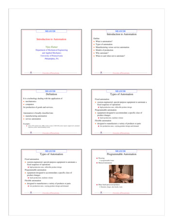
1. This tool can be found at ml.1Toggle the sliders until you achieve the desired airfoil.Figure 2: Web-based profile generator and Excel file containing airfoil profile data points2. Copy the coordinate points and paste into a new Microsoft Excel document.3. Depending on the version of Excel being used, sometimes both the x and y datapoints show up in the same column when copied from the Profile Generator table.To fix this problem so that column A corresponds to x -axis points only, andcolumn B corresponds to y-axis points only, click on Data (in the toolbar) Textto Columns. Within the Convert Text to Columns Wizard, select delimited fororiginal data type and then tab and space as the delimiters. Now the x and y datashould be in two different columns.Using the Equation For a 4-Digit NACA Airfoil The second method involves usingNACA formulas to define the shape of the airfoil.1Profile generators for NACA 5 digits series and ellipses can also be found html and ./profiles/Ellipse.html, respectively.2
1. To define the shape of a symmetrical 4-digit NACA airfoil (i.e. NACA 00xx): x x 12 x 2 x 3 x 4 ty c 0.12600.2969 0.3517 0.2843 0.10150.20ccccc2. For a cambered 4-digit airfoil, we must first define the mean camber line using thefollowing piecewise equation:(y m px2 2p c xm (1 p)2xc 1 xc0 x pc 2p pc x cOnce the mean camber line is defined, the coordinates of the upper and lowerairfoil surface (xU ,yU ) and (xL ,yL ) are given by:3xU x y sin θ,yU yc y cos θxL x y sin θ,yL yc y cos θDrawing the Airfoil Curve1. Create a new SolidWorks part document2. From the toolbar select Tools Options Document Properties (tab) to units. Selectthe desired unit system. Since we have data points for a unit-length airfoil, the chordof the airfoil will be one of whatever unit the document is in. The chord length canthen be specified by scaling the profile after it is inserted.3. From the toolbar select Insert Curve Curve Through XYZ Points.4. A window titled Curve File will appear. Within this window, select Browse. ChangeFiles of type: from Curves (*.sldcrv) to Text Files (*.txt) and then select the filecontaining the airfoil profile points.5. Once the profile points are in the Curve File window, select OK. A curve is now insertedinto the SolidWorks model view.6. The curve we have just inserted shows up as Curve1 in the FeatureManager design treeon the left hand side of the screen. However, in order to create solid geometry, we mustfirst convert this curve into a sketch.3
Figure 3: Curve file windowFigure 4: After creating a sketch and converting curve entities, the airfoil appears with blacklines in the SolidWorks model view.7. To create a sketch that is based on the curve, first insert a new sketch by selecting theSketch tool from the CommandManager toolbar. SolidWorks should by default insertthe airfoil curve on the front plane, so select the front plane as the sketch plane.8. Now we can create a sketch defined by the airfoil curve by first selecting the curve andthen selecting Convert Entities, which can be found in the CommandManager toolbar.The curve should appear black in color, which indicates a fully defined sketch. We arenow ready to use this sketch to create 3D geometry.4Creating 3D GeometryThis section details methods of creating 3D wings from the 2D airfoil profile.4
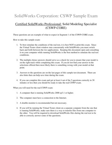
Extruded Feature Extruding the sketch profile will create a simple wing. This featurewill not provide any curvature to the wing, nor will it allow the wing to be taperedgradually towards the tip.1. From the CommandManager toolbar, select Extruded Boss/Base.2. If your sketch is not already selected, you will be asked to select an existing sketchto use for the feature. Select the sketch of the airfoil profile.3. From the FeatureManager, change the depth of the extrusion to achieve the desiredspan.4. Click the green check mark to execute the feature, and save the .SDLPRT file.Figure 5: An extruded featureSwept Feature Sweeping the sketch profile through a path provides a higher degree offlexibility in comparison to the extrusion feature.1. To begin, we must first insert a path line through which the profile will be swept.Once again, a curve can be inserted from a .txt file containing data points in thesame manner in which the airfoil profile was inserted, but it is also possible tosimply insert a new sketch and draw a line or a spline.2. Make sure you have exited the sketch containing the profile, and then select Sketchand then Sketch again from the CommandManager toolbar.5
3. The panel on the left hand side of the screen will ask you to select a plane onwhich to create a sketch. With the airfoil profile already oriented on the frontplane, select the top plane (if the planes are not displayed, open up the part tree).4. Orient the view such that you are normal to the top plane. This can be accomplished be either opening the Standard Views drop-down menu in the Viewtoolbar, or by pressing the spacebar on the keyboard and selecting top.5. Select either the line or spline tool from the CommandManager toolbar, and createthe desired sweep path next to the airfoil profile, avoiding any automatic relationsSolidWorks may try to insert.6. Select Add Relation from the CommandManager toolbar and select the endpointof the path line and the profile sketch.7. Within the Add Relations side panel, define the relation as Pierce. Select thegreen check mark to insert the relation. This relation is necessary to create aswept feature.8. Exit the sketch and select Swept Boss/Base from the feature option in the CommandManager toolbar.9. The Sweep sidebar will ask you to select a sweep profile and a sweep path. Selectthe airfoil profile sketch as the sweep profile, and the line/spline sketch as thesweep path.10. Notice that the span and shape of the wing depends on the sweep path sketch thatwas previously inserted. If you would like to go back and change the length or pathof the sweep path, first select the green check mark to execute the sweep feature.An item entitled Sweep1 appears in the FeatureManager design tree. Expand thesweep feature by selecting the plus symbol next to it, right-click on the sketch thatcontains the sweep path, and select Edit Sketch. Any changes made to the sweeppath will automatically rebuild in the sweep feature after you exit the sketch.11. The sweep feature can also be edited by right-clicking on it in the design tree.Some options that may be of interest can be found in the Orientation/twist typedrop-down menu. For example, if you are creating prop blades, you may want tohave the airfoil profile twist along the path.Lofted Feature Lastly, we can employ the loft feature to create wings that have longitudinaltwist, bend, and a non-constant chord length. 22Additionally, we could even use lofts to create wings with non-constant airfoil geometry.6
Figure 6: A swept feature with a curved profile path1. To use the loft feature, we must insert a new plane as reference geometry. Beforedong this, first right-click the front plane in the FeatureManager design tree, andselect show.2. Now go to Insert Reference Geometry Plane. Select the front plane fromthe model view, and set the distance between this plane and the new plane to bethe desired span of the wing. Select the green check mark to insert the plane. Thereference geometry plane should appear in the model view and the design tree.3. Insert a new sketch on the reference plane (probably named Plane1 ).4. Orient the view normal to the reference plane, select the airfoil profile that issketched on the front plane, and convert entities. This tool copies the airfoil curveinto the sketch on the reference plane.5. In the case of wanting to create a wing with a non-constant chord length (i.e. a‘taper’) we can scale the airfoil sketch on the reference plane. To do this, selectTools Sketch Tools Scale.6. If the sketch isn’t already selected, select the airfoil curve on the reference plane.Spline2 will appear in the Entities to Scale box in the side panel.7. Under Parameters, you must choose a point to scale about. You can click anywherein the sketch to define a point to scale about. Finally, specify a scale factor, andselect the green check mark to execute.7
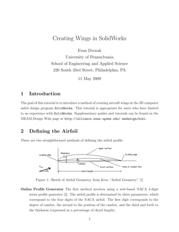
Figure 7: Inserting a reference plane and scaling a sketch8. Insert a loft by selecting Lofted Boss/Base from the CommandManager toolbar.9. In order to create a loft, we must select at least two profiles. Select the airfoilprofile sketch on the front plane and the scaled-down profile sketch on the referenceplane.10. The loft generated by SolidWorks is most likely not the loft that is desired. Thereare many different ways in which we can modify the loft feature. First, you willnotice a teal-blue circle that appears on each of the selected profiles. These circlesmark the points that are synchronized between the profiles. These markers can beclicked-and-dragged around to modify the synchronization between the profiles.Figure 8: A lofted feature with a scaled-down end profile8
11. The start/end constraints can also be modified to create the differently shapedwings. Within the Start/End Constraints box in the Loft editor, change StartConstraint from None to Normal to Profile. This option causes the loft faces tostart normal to the sketch profile. If the start constraint for the airfoil profilesketch is Normal to Profile at the root, and there is no constraint on the scaleddown profile at the tip of the wing, the resulting loft will be parabolic in shape.12. Guide curves can also be used for lofted features in a way that is similar to howthey are used for swept features. In lofts, guide curves specify the geometrybetween the profiles.13. Although there are other options that can be used in loft features, the last optionI will mention is using multiple scaled and/or rotated airfoil profiles in a singleloft. In this way, the wing geometry can be highly specified.5Measurements, Mass Properties, RenderingOnce the wing is created, SolidWorks is capable of telling you some useful informationabout the wing, such as the dimensions, surface area, and moments about various axes(once a material is assigned). Finally, realistic material renderings can be producedusing the PhotoWorks tool.Measurements SolidWorks is capable of determining the dimensions and surface area ofthe wing.Figure 9: Making measurements9
1. Go to Tools Measure.2. To determine the span of the wing select the flat face at both the root and tip endof the wing. SolidWorks will display the distance between the two faces, as wellas a breakdown of the distance in (x,y,z) components.3. The surface area of the wing can be determined by selecting the curved surface ofthe geometry.Mass Properties Additionally, one can assign a material to the geometry to obtain information on the mass properties of the wing, such as total mass, center of mass, and themoments of inertia about various axes.Figure 10: Mass properties window1. A material must be assigned to the wing before SolidWorks can provide information about its mass properties. To do this, right-click in the FeatureManagerdesign tree where it says Material not specified, and select Edit Material.2. If the wing is to be printed using the Dimension Elite 3-D printer, select ABS(under plastics) as the material. If the wing is going to be fabricated from a seriesof laser-cut acrylic segments, select Acrylic (Medium-high impact).3. Notice that at the bottom of the Materials Editor side panel there is a box titledPhysical Properties. Properties such as elastic modulus, Poisson’s ratio, shear10
modulus, density, etc. are provided by SolidWorks, assuming that a material wasassigned.4. Select the green check mark to save the material to the wing.5. Now, select Tools Mass Properties. Various mass properties, such as center ofmass (relative to the part origin), and the moments of inertia about various axesare computed.Rendering Lastly, one can prepare attractive SolidWorks renderings of the wing geometryusing the PhotoWorks feature, a rendering tool that is built in to the SolidWorksprogram.1. On the right-hand side of the screen, select the PhotoWorks Items button todisplay the PhotoWorks task pane.2. Select a renderable material from the task pane, and drag the material name ontothe SolidWorks part.3. To add a background scene and lighting, do the same for any of the variousStudios. Lights can also be inserted manually by dragging a light into the windowcontaining the part.Figure 11: Renderings of the swept feature (left) and lofted feature (right). The materialshown is polished aluminum and the studio is Daytime.References[1] Kroo, “Airfoil Geometry”, etry.html(2006)11
[2] ppart.de/aerodynamics/profiles/NACA4.html (2009)Generator”,[3] Ladson, Brooks, Hill, ”Computer Program To Obtain Ordinates for NACA Airfoils”,NASA Technical Memorandum 4741, National Aeronautics and Space Administration,(1996)12
3 Drawing the Airfoil Curve 1. Create a new SolidWorks part document 2. From the toolbar select Tools !Options !Document Properties (tab) tounits. Select the desired unit system. Since we have data points for a unit-length airfoil, the chord of the airfoil will be one