Transcription
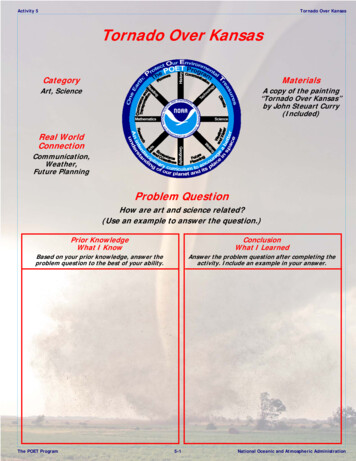
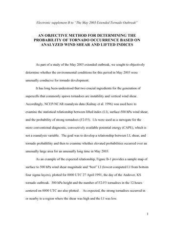
Suction VortexTornadic VortexThe conditions in which tornadoes form include:Contrary to the predictions of fluid dynamics, tornadoes behave verydifferently. Instead of the air converging in the direction of the flow, the airconverges at the ground level, where an extreme low pressure hasdeveloped, away from the source of the low pressure aloft. Inside the vortex,the low pressure relaxes in the direction of the flow, and the vortex widenswith proximity to the source of the low pressure. In other words, the "funnel"points downward.1. a low pressure aloft (i.e., the updraft within the thunderstorm),2. a high pressure at the ground level coming from a "forced downdraft" (i.e.,the rear flank downdraft), and3. angular momentum in the inflow, due to interactions among the rear flankdowndraft, the forward flank downdraft, and the surface winds.And, of course, all of this occurs in an open-air system.In these conditions, the air should converge as it approaches the source ofthe low pressure. In other words, the "funnel" should be pointing upward.A vortex with these properties has never been produced in the laboratoryusing realistic conditions, and off-the-shelf CFD programs given suchconditions resolve into standard suction vortexes (such as at left), nottornadic vortexes.The purpose of this experiment is to identify the force(s) responsible forvortexes with these characteristics.SpatiousDesigns743 Wilton Farm DriveBaltimore MD 21228DESIGNERCharles L. ChandlerCLIENTSCS-INC.USFILENAMETornado Vortex Exp.vwxRevisions1. 2009-01-24 posted2. 2009-08-05 removedtoroidal winding3. 2010-09-18 removedsealed enclosure,added tornadic current4. 2011-01-07 addedcomments from KevinJohnston5. 2011-04-01 addedelectronics schematicfrom Kevin JohnstonDrawing List01. Definitions02. Strategy03. Overall Dimensions04. Lower Platform05. Fogger Assembly06. Upper Platform07. Control Panel08. Ion Generators09. Parts List10. Test Procedure11. Data SheetPROJECTTornadic Vortex TestTITLEDefinitionsSCALE3/4" 1'-0"SHEET01
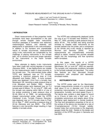
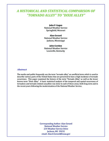
In any open-air system, kinetic energy should dissipatewith distance from the source of the energy, due tofriction. A concentration of kinetic energy, away fromthe source of the energy, is evidence of the presence ofanother force that has created a bottleneck in the flow.Vortexes strikingly similar to tornadoes have beendemonstrated in the laboratory by pulling rotating airthrough a bottleneck. Once past the restriction, the lowpressure relaxes in the direction of the flow, and theradius of the vortex expands. (See Ward, N. B., 1972:The exploration of certain features of tornado dynamicsusing a laboratory model. Journal of the AtmosphericSciences, 29: 1194-1204.) But the scientists failed todemonstrate how such a bottleneck could exist in situ.The force that restricts the airflow, and that generatesthe extreme low pressure away from the source of thelow pressure, is, by definition, non-fluid dynamic. In atornado, the only non-fluid dynamic force present is theelectric force. The following assertions are made.1. The inflow to a tornado is bearing a positive charge,which induces a negative charge in the Earth, resultingin an electrostatic attraction of the air to the Earth.2. As the air flows toward the tornado, its proximity tothe ground introduces friction, slowing it down. Thiscreates the bottleneck, and causes the low pressure inthe vortex to extend all of the way to the ground.a single, central inlet in the bottom of that platform (notshown), establishing the primary flow field, analogousto a mesocyclone. The speed of the fans will besufficient to create a weak vortex in the "mesocyclonic"inflow of ambient air up into the upper platform.Inside the lower platform, air will be humidified, ionized,and then forced out across the top of the lowerplatform, analogous to the rear flank downdraft.SpatiousDesignsTo neutralize the positive charge in the tornadic inflowclinging to the lower platform, a set of negative iongenerators will be attached to the underside of theupper platform. The free electrons so generated will beattracted to the positive ions below, and will flowdownward, through the reduced resistance in thevortex. Where such electrons neutralize the positivecharge, the air will be free to respond to the lowpressure above.743 Wilton Farm DriveBaltimore MD 21228DESIGNERThe top of the lower platform will be be covered with apiece of sheet metal connected to ground, so that it willact as a solid conductor, analogous to the Earth. Theionized air will induce an opposite charge in the sheetmetal, and then be attracted to it.The experiment will be considered successful if it candevelop an extreme low pressure, away from thesource of the low pressure, with the fastest air speedswhere the friction is the greatest, using only fluiddynamic and electric forces within realistic ranges.Charles L. ChandlerCLIENTSCS-INC.USFILENAMETornado Vortex Exp.vwxRevisions1. 2009-01-24 posted2. 2009-08-05 removedtoroidal winding3. 2010-09-18 removedsealed enclosure,added tornadic current4. 2011-01-07 addedcomments from KevinJohnston5. 2011-04-01 addedelectronics schematicfrom Kevin JohnstonNotes3. The low pressure inside the vortex increases theconductivity of the air, allowing the flow of electrons,from the main negative charge region inside the stormdown through the tornado, attracted to the positivelycharged inflow.4. The electrons flowing down through the tornadoneutralize the positive charge in the tornadic inflow.Once the charge is neutralized, the air is no longerattracted to the Earth, and the air is then free to ascend.Hence the air is released from the bottleneck.5. The updraft inside the tornado is ultimately motivatedby several factors. As the air flows along the groundtoward the tornado, skin friction generates heat. Theneutralization of its charge inside the vortex alsogenerates heat. As the air rises inside the tornado, it isexposed to resistive heating from the flow of electronsthrough the vortex. All of these heat sources increasethe buoyancy of the air, which combines with the lowpressure aloft, resulting in a high vertical velocity. Andthis, combined with the bottleneck created by skinfriction near the ground, results in an extreme lowpressure, away from the source of the low pressure.The present apparatus will attempt the recreate therelevant aspects of these in situ conditions within acontrolled environment.Fans on top of the upper platform will pull air throughPROJECTTornadic Vortex TestTITLEStrategySCALE1" 1'-0"SHEET02
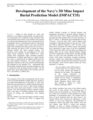
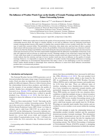
SpatiousDesigns743 Wilton Farm DriveBaltimore MD 21228DESIGNERCharles L. ChandlerCLIENTSCS-INC.USFILENAMETornado Vortex Exp.vwxRevisions1. 2009-01-24 posted2. 2009-08-05 removedtoroidal winding3. 2010-09-18 removedsealed enclosure,added tornadic current4. 2011-01-07 addedcomments from KevinJohnston5. 2011-04-01 addedelectronics schematicfrom Kevin Johnston47.750CommentsThere will be 4 fans on top, to pull the air upward, analogous to amesocyclone, while there will only be 1 fan at the bottom pushing airtoward the centerline, analogous to a rear flank downdraft. As themesocyclone draws in much more air than the tornado, this is correct.variable72.000The reason for using 4 small fans in the corners of the top platform,instead of 1 big fan in the middle, is that we need to generate negativeions in the mesocyclonic inflow, analogous to the powerful negativecharge in the hook echo, and we need these ions to be attracted tothe positive charge below, not the grounded fan casing(s) above. Sothe fan(s) have to be as far as is practical from the ion generators.Furthermore, we cannot allow the air pressure to decrease as ittravels from the ion generators toward the fan(s) as it normally would.The reason is that lower-pressure air is a better conductor, and thiswould set up a low-resistance path to the fan casing(s) that we can'thave. So the upper platform will be a vacuum chamber, where thelowest pressure at the large intake hole will be split into 4 paths, eachwith 1/4 the low pressure of the intake hole itself. Hence, the electricalresistance will increase in the direction of the flow inside the vacuumchamber, discouraging the flow of electrons toward the fan casings.Notes1. The height of theplatforms will be setsimply by drivingdrywall screws throughthe 1x4 legs into theplatforms.2. All surfaces will becoated with blackepoxy paint. The blackcolor will allow thephotography to beover-exposed,improving the visibilityof the vortex. The paintitself will make thewood in the apparatusimpervious to moisture,and the epoxy willinsulate the parts.PROJECTTornadic Vortex TestTITLEOverall DimensionsSCALE3/4" 1'-0"SHEET03
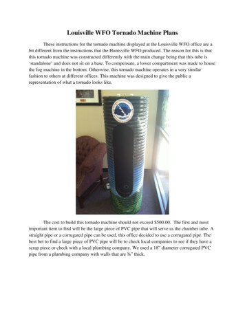
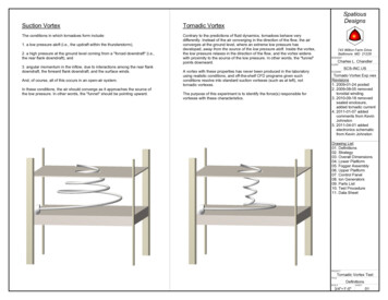
1x4#2 pine(typ)SpatiousDesignssealedcordportfogger (x6)743 Wilton Farm DriveBaltimore MD 21228DESIGNERCharles L. do Vortex Exp.vwxRevisions1. 2009-01-24 posted2. 2009-08-05 removedtoroidal winding3. 2010-09-18 removedsealed enclosure,added tornadic current4. 2011-01-07 addedcomments from KevinJohnston5. 2011-04-01 addedelectronics schematicfrom Kevin Johnstonpositive CWmultipliers (x8)Commentsvent to topof platformThere have been numerous discussions on how to humidify andionize air. This design attempts to address the issues in a relativelypractical way.The air has to be humidified first, and then ionized. The reason isthat if it was ionized first, then the charged air would subsequentlybe forced into proximity with the humidifier, which is an electricalappliance of some sort, and which therefore is grounded. Hence wewould expect the charge in the ionized air to go to ground rightthere, eliminating the ionization. So we humidify the air first, andthen ionize it.heaterfanfoggerBut this presents another problem. Moist air is a better conductorthan dry air. So when moist air passes through an ionization lattice,we expect the charge to follow the moisture back to the groundedhumidifier. To reduce the charge loss, we force the air through amaze within the lower platform, to increase the distance from thehumidifiers to the ionizer lattice, thereby increasing the electricalresistance. The increase in pressure due to friction in the maze willalso increase the resistance of the air slightly.Notes1. The purpose of thisassembly is to create asupply of warm, humid,positively-charged airtraveling across the topof the lower platform,analogous to the aircoming from the rearflank downdraft thatflows into the tornado.2. The fan will exhaust airinto the plenum, whereit will be humidified byfoggers, and thenionized byCockcroft-Waltonmultipliers before beingvented out the top.3. The top and bottomMDF panels will beattached to the 1x4frame with drywallscrews, and with foamweatherstripping tocreate an air seal.PROJECTTornadic Vortex TestTITLELower PlatformSCALE3/4" 1'-0"SHEET04
SpatiousDesigns743 Wilton Farm DriveBaltimore MD 21228DESIGNERCharles L. ChandlerCLIENTSCS-INC.USFILENAMETornado Vortex Exp.vwxRevisions1. 2009-01-24 posted2. 2009-08-05 removedtoroidal winding3. 2010-09-18 removedsealed enclosure,added tornadic current4. 2011-01-07 addedcomments from KevinJohnston5. 2011-04-01 addedelectronics schematicfrom Kevin Johnstonfoggerw/ buoy6.0004.348Ocean Mist Maker MDC01 fogger buoyNotes1. Humidification will beaccomplished withultrasonic foggers.2. Each unit will be aglass jar, with a foggersubmerged in water.3. The lids of the jars willbe screwed to thebottom of the platform,and sealed withweatherstripping, sincethe plenum needs to beairtight.PROJECTTornadic Vortex TestTITLEFogger AssemblySCALE3" 1'-0"SHEET05
TOPcircular pieceof plywood toact as baffleSpatiousDesignsBOTTOMvacuum chamber inletfan743 Wilton Farm DriveBaltimore MD 21228DESIGNERCharles L. ChandlerCLIENTSCS-INC.USFILENAMEnegative CW multiplier (x8)parachute cordpulley (x4)pulley (x2)cleatcircular pieceof plywood toact as bafflepulley (x4)negative CWmultiplier (x8)vacuumchamberinlet12.000parachutecord to lowerplatform (x4)Tornado Vortex Exp.vwxRevisions1. 2009-01-24 posted2. 2009-08-05 removedtoroidal winding3. 2010-09-18 removedsealed enclosure,added tornadic current4. 2011-01-07 addedcomments from KevinJohnston5. 2011-04-01 addedelectronics schematicfrom Kevin JohnstonNotes1. The fan mounted abovethe upper platform willpull air through a largehole in the bottom ofthe platform, creating alow pressure analogousto a mesocyclone.2. The large hole at thebottom of the platformwill be lined withCockcroft-Waltonmultipliers to generatenegative ions. This willsupply the electronsthat will flow downthrough the vortex, toneutralize the positivelycharged air coming outof the lower platform.3. The circular baffle willprovide separationbetween the ionizersand the grounded fancasing, so the ionswon't go to ground inthe fan casing.PROJECTTornadic Vortex TestTITLEUpper PlatformSCALE3/4" 1'-0"SHEET06
SpatiousDesigns743 Wilton Farm DriveBaltimore MD 21228DESIGNERCharles L. ChandlerCLIENTSCS-INC.USFILENAME302040 50 60708010900100Vacuum2103 4 5678Negative23 4 561708Positive302040 50 60708010900100Plenum23 4 561708Foggers302040 50 60Tornado Vortex Exp.vwxRevisions1. 2009-01-24 posted2. 2009-08-05 removedtoroidal winding3. 2010-09-18 removedsealed enclosure,added tornadic current4. 2011-01-07 addedcomments from KevinJohnston5. 2011-04-01 addedelectronics schematicfrom Kevin Johnston708010900100HeaterNotes1. The main enclosure willbe a NEMA-1 (generalpurpose) groundedsteel box.2. Input and output will be120 VAC.3. The ionizers andfoggers are not fittedwith variable control foreach appliance, soexperimental variabilitywill be accomplishedsimply with the numberof appliances that areswitched on, assumingthat one is not enough,and all of them will beplenty. So these will becontrolled with SP8Tswitches.4. The fans and theheater will be controlledby rheostats.PROJECTTornadic Vortex TestTITLEControl PanelSCALE3" 1'-0"SHEET07
SpatiousDesignsCaution: High Voltage!Only certified personnel should build such devices.743 Wilton Farm DriveBaltimore MD 21228DESIGNERCharles L. ChandlerCLIENTSCS-INC.USFILENAMEPhilmore 80-570 Ion Generator(Cockcroft-Walton Multiplier)110 VAC in, 5 kVDC outTornado Vortex Exp.vwxRevisions1. 2009-01-24 posted2. 2009-08-05 removedtoroidal winding3. 2010-09-18 removedsealed enclosure,added tornadic current4. 2011-01-07 addedcomments from KevinJohnston5. 2011-04-01 addedelectronics schematicfrom Kevin JohnstonNotesPROJECTTornadic Vortex TestTITLEIon GeneratorsSCALESHEETnone08
QtyDimensions?1" x 4" x 8'447.75" x 47.75"1quart?SupplierSpatiousDesignsboards -- for feet and for platform ribs1/2" particle board (MDF) -- for top and bottom of upper and lower platformsflat black epoxy paintfoam weatherstripping -- to seal platforms1 lb.1 1/4"147.75" x 47.75"2010" x 10"1Description4"drywall screws -- for screwing together the platform piecessheet metal -- to form the plane conductor at the bottomplastic grass mats -- for increasing skin friction of lower platform743 Wilton Farm -p-73636.Baltimore MD 21228DESIGNERPVC 90 elbowCharles L. ChandlerCLIENT162" x 4"Cockcroft-Walton 7121.5" dia x 1.25" hOcean Mist Maker MDC01 ultrasonic fogger -- to humidify the les.html124" dia x 2.5" hOcean Mist Maker K011 buoy -- to control the depth of the fogger124.25" dia x 6" hglass jar with metal lid -- sump for fogger250W, 12"232.000DC fanswww.grainger.com/Grainger/items/4WT42PVC pipe (?) -- for fan ?sku 26314SP8T switches -- to control ionizers and .html1power distribution box (mains & control input, PWM/CW/etc output)1control panel21000W24' tallwww.factorymation.com/s.nl/it.A/id.4327/.f?sc 2&category 4838flood light -- to illuminate the vortexSCS-INC.USFILENAMETornado Vortex Exp.vwxRevisions1. 2009-01-24 posted2. 2009-08-05 removedtoroidal winding3. 2010-09-18 removedsealed enclosure,added tornadic current4. 2011-01-07 addedcomments from KevinJohnston5. 2011-04-01 addedelectronics schematicfrom Kevin JohnstonNoteslamp stands1camera -- for photography and videography1thermo/hygrometer -- to measure ambient and RFD air (Exo Terra PT2470)1barometer -- to measure ambient atmospheric pressure1anenemometer -- to measure airspeedwww.maine-hardware.com/viewproduct.php?i B0002WZRKE1air ion ive .com/en/products/combometer.phpPROJECTTornadic Vortex TestTITLEParts ListSCALESHEETnone09
SpatiousDesignsTest Procedure1. Leave the ground wire for the plane conductor at the bottom (the sheet metal)disconnected.2. Turn on the lower heater-fan, and let it run for 10 minutes, to pre-heat the lowerplatform. This will get the walls of the air channel warmer than the humidified airthat will pass through it later, discouraging condensation on the walls that wouldprovide a path to ground for the ionized air.3. Turn on the foggers. Wait for the humidity to rise until a vortex becomes visiblebelow the upper platform (i.e., the "mesocylonic" vortex).4. Use an anemometer to measure the speed of the air coming out of the fans, sothat this can be correlated with the PWM settings in successive trials, withouthaving to measure the air directly (especially after it is charged).5. Set the humidistat to maintain that humidity for the duration of the trials.6. Wait until the humidity stablilizes.7. Take photography/videography of the vortex in this state, and record allparameters.8. Turn on the ionizers. Allow the airflow to stabilize. At this point, the ground wirefor the sheet metal should still be disconnected, so the air shouldn't be bindingto the lower platform. In this configuration, a shallow wedge of condensationshould form, but it will not project to the lower boundary, and there will not beorganized rotation at the bottom.9. Take photography/videography of the vortex in this state, and record allparameters.743 Wilton Farm DriveBaltimore MD 21228DESIGNERCharles L. ChandlerCLIENTSCS-INC.USFILENAMETornado Vortex Exp.vwxRevisions1. 2009-01-24 posted2. 2009-08-05 removedtoroidal winding3. 2010-09-18 removedsealed enclosure,added tornadic current4. 2011-01-07 addedcomments from KevinJohnston5. 2011-04-01 addedelectronics schematicfrom Kevin JohnstonNotes10. Connect the ground wire for the plane conductor. The vortex should then bindto the bottom of the enclosure.11. Take photography/videography of the vortex in this state, and record allparameters.12. Turn off the ionizers, but leave the upper fans running, as well as the lowerheater-fan, with the foggers still running, to clear out charges that could havebuilt up in the platform.13. Turn off the foggers, and let the fans run another 10 minutes, to clear out anycondensation that could have formed in the lower platform, and that could shortout the ionizers on re-start.14. Turn off everything, and discharge potentials with a ground wire.15. Disconnect all equipment from AC mains.PROJECTTornadic Vortex TestTITLETest ProcedureSCALESHEETnone10
Year:Mo-DyHr:Mi:ScAmbientmb CUpperRHm/skVHghtcmLowerkVm/sRH CphotovideoSpatiousDesignsComments743 Wilton Farm DriveBaltimore MD 21228DESIGNERCharles L. ChandlerCLIENTSCS-INC.USFILENAMETornado Vortex Exp.vwxRevisions1. 2009-01-24 posted2. 2009-08-05 removedtoroidal winding3. 2010-09-18 removedsealed enclosure,added tornadic current4. 2011-01-07 addedcomments from KevinJohnston5. 2011-04-01 addedelectronics schematicfrom Kevin JohnstonNotes1. Specify time to thesecond if a photo (witha timestamp) is taken.2. mb is the millibars ofambient pressure.3. RH is the relativehumidity in percents.4. m/s is the rate of flowmeasured in the centerof the stream, into theupper fan and out ofthe lower fan.5. kV is the reading on thevoltmeter showing thetotal voltage applied tothe needle matrices(negative for the upperand positive for thelower). It does notmean the degree ofresulting space charge.6. Hght is the height in cmof the upper platformabove the lower.7. If there is an associatedphoto or video, markwith P or V.PROJECTTornadic Vortex TestTITLEData SheetSCALESHEETnone11
4. The electrons flowing down through the tornado neutralize the positive charge in the tornadic inflow. Once the charge is neutralized, the air is no longer attracted to the Earth, and the air is then free to ascend. Hence the air is released from the bottleneck. 5. The updraft inside the tor