Transcription
Journal of Counter-Ordnance Technology (Sixth International Symposium on Technology and Mine Problem, NPS, 10-13May, 2004)1Development of the Navy’s 3D Mine ImpactBurial Prediction Model (IMPACT35)Dr. Peter C Chu, LCDR Ashley Evans, LCDR Anthony Gilles, LCDR Timothy Smith, and LCDR Victoria TaberNaval Ocean Analysis and Prediction Laboratory, Oceanography DepartmentNaval Postgraduate School, Monterey, California, USAwarfare doctrine concepts of forward presence andengagement developed as National Defense Strategy in“Joint Vision 2010, 1996”, (Rhodes and Holder 1998). Thedocument provided guiding tenets for naval operations ofthe 21st century. A subsequent Naval Department revision,“Forward From the Sea, 1994”, and its Marine Corpcounterparts “Operational Maneuver from the Sea, 1996”,and “Ship to Objective Maneuver, 1997” all focus on seabased power projection into littoral regions and guidingnaval operations in those areas in the new millennium.“Joint Vision 2020, 2000” and “Sea Strike, Sea Shield, SeaBasing, 2002” are the current National Defense Strategyand Naval Department concept papers providing guidingtenets for naval and joint operations well into the 21stcentury. Both papers incorporate emerging technology,processes, people and organizations synergized via thenetcentric warfare concept to provide total power projectionand dominance across littoral regions during any crisesrequiring U.S. response.Atract-- Falling of mine through air, water, andsediment is investigated experimentally and theoretically.Two experiments were conducted to drop cylindrical minewith the density ratio around 1.8 into shallow water (around13 m deep) in the Monterey Bay (Exp-1) and into the NavalPostgraduate School’s swimming pool (Exp-2). During theexperiments, we carefully observe mine track and burialdepth while simultaneously taking gravity cores (in Exp-1).After analyzing the gravity cores, we obtain the bottomsediment density and shear strength profiles. Thetheoretical work includes the development of 3D mineimpact burial prediction model (IMPACT35) whichcontains three components: triple coordinate transform,hydrodynamics of falling rigid object in a single medium(air, water, or sediment) and in multiple media (air-waterand water-sediment interfaces). The model predicts therigid body’s trajectory in the water column and burial depthand orientation in the sediment. The experimental data(burial depth, sediment density and shear strength) are usedto evaluate the newly developed numerical model. The 3Dmodel shows great improvement to the currently used USNavy’s 2D model (i.e., IMPACT28).the very shallow water (VSW) region isa critical point for our offensive forcesand can easily, quickly and cheaply beexploited by the enemy. The magnitudeofthecurrentdeficiencyinreconnaissance and neutralization in theseregions and the impact on amphibiousassault operations were demonstratedduring Operation Desert Storm. Maj.Gen. Edward J. Hanlon Jr. “From(Rhodes and Holder 1998).”1. IntroductionThe conclusion of the cold war culminated with the Unionof Soviet Socialist Republics (USSR) effectively ceasing toexist under international law on December 31, 1991. Thishistorical event caused the U.S. military and specifically theNavy and Marine Corp Team to shift tactical emphasisfrom blue water, deep ocean doctrine to littoral warfaredoctrine. This shift predicated military responses dealingwith a wide range of worldwide regional crises requiringforward sea basing, and expeditionary force landingsupport.The Navy Marine Corp team developed a doctrine conceptwhite paper, “ From the Sea, 1992”, to support jointAny military operation that occurs in the littoral regionsalso occurs in mine country. The increasing pace ofshallow-water naval operations (i.e. Persian Gulf, AdriaticSea, Yellow Sea, and Gulf of Aden) translates into a highprobability of encountering mines. The required shift infocus of naval operations from the open ocean to theregional littoral areas increases the importance of minewarfare as a navy core competency. The proliferation ofinexpensive, bottom type mines make shallow water andvery shallow water MCM a critical and expensivechallenge. In times of conflict domination of coastaloperating areas will largely depend on the ability to removeManuscript received January 15, 2004. This work was supported by theU.S. Office of Naval Research, Naval Oceanographic Office, and NavalPostgraduate School.Peter C. Chu is with the Naval Postgraduate School, Monterey, CA93943 USA (telephone: 831-677-3688, e-mail: chu@ nps.navy.mil).1
Journal of Counter-Ordnance Technology (Sixth International Symposium on Technology and Mine Problem, NPS, 10-13May, 2004)or neutralize any emplaced littoral mine threat, figure 1,and prepare the battle space for follow-on action in a timelyfashion Naval mines may be found throughout the watercolumn and on or within the seafloor. Ask anyone todescribe a typical naval mine to you and the response willbe a description of the spherical, hertz-horn World War IIvintage drifting mine shape common in Hollywood films.But, it is the buried naval mine that poses the most severethreat to naval assets since naval forces possess verylimited resources and capabilities for detecting, identifying,and neutralizing them, and the mine itself remains fullyeffective when buried, (Lott, 2001). An important factor inmine hunting and clearance is the amount of initial impactand subsequent sediment burial a mine undergoes with timebecause buried mines are substantially more difficult todetect and classify. The amount of burial becomes a criticalparameter and crossroad in the naval MCM missionplanning process because the mine countermeasures efforttransitions from mine hunting to mine sweeping, (Rennie2002.) Littoral Mine Threat. “From (Rhodes 1998).”2burial process. Several revisions have occurred in the lasttwo decades but there have been limitations noted in themodel performance, as well as little scientific advancementin mine burial prediction, (Dolan et al 1999), (Taber 1999),(Smith 2000), and (Gilless 2001).In this study, a nonlinear dynamical system (IMPACT35)is established for the movement of a nonuniform (center ofgravity not the same as the center of volume) mine throughthe water-sediment interface. A cylinder-drop experimentwas conducted. The data collected from the experiment canbe used for model development and verification. The longterm goal is for model inclusion in a full spectrumdeterministic model for mine burial in a comprehensivenavy tactical decision aid.2. Triple Coordinate SystemsConsider an axially symmetric cylinder with the centersof mass (COM) X [or called gravity center (GC) inliteratures] and center of volume (COV) B on the main axis(Fig. 2a). Let (L, R, χ ) represent the cylinder’s length,radius, and the distance between the two points (X, B). Thepositive χ -values refer to nose-down case, i.e., the point Xis lower than the point B. Three coordinate systems areused to model the falling cylinder through the air, water,and sediment phases: earth-fixed coordinate (E-coordinate),main-axis following coordinate (M-coordinate), and forcefollowing coordinate (F-coordinate) systems. All thesystems are three-dimensional, orthogonal, and righthanded ([2] Chu et al. 2004).The E-coordinate is represented by FE(O, i, j, k) with theorigin ‘O’, and three axes: x-, y- axes (horizontal) with theunit vectors (i, j) and z-axis (vertical) with the unit vector k(upward positive).The position of the cylinder isrepresented by the COM position,X xi yj zk.(1)The translation velocity is given bydX V , V ( u, v , w).(2)dtLet orientation of the cylinder’s main-axis (pointingdownward) is given by iM, and ψ 1 be the angle that theMine warfare, perhaps more than anyother single littoral warfare mission areais the “key” that will unlock the “door” tothe littoral battle space. In the mostfundamental way, then, mine warfare andtheneedforeffectiveminecountermeasures must be an “all-hands”concern for the Navy and the MarineCorps. (Boorda 1995)cylinder rotates around the axis iM. The angle between iMand k is denoted byψ 2 π / 2 . Here, ψ 2 is usually calledFig.1. Littoral Zone Mine Treat (fromRhodes 1998).the elevation angle. Projection of the vector iM onto the (x,y) plane creates angle (ψ 3 ) between the projection and theThe Office of Naval Research (ONR) in 1999 created theMine Burial Program (MBP), an applied (6.2) researchprogram to develop mine burial prediction tools anddecision aids. The program mission is to predict thebehavior of mines in different environments, (Bennett2000). The Impact Mine Burial Prediction modeldevelopment falls under the MBP program.The Impact Mine Burial Prediction model developed in1980 was developed to semi-empirically model the minex-axis (Fig. 2b). The M-coordinate is represented by FM(X,iM, jM, kM) with the origin ‘X’, unit vectors (iM, jM, kM), andcoordinates (x(m), y(m), z(m)). The unit vectors of the Mcoordinate system are given by (Fig. 2b)jM k i M , k M i M j M(3)2
Journal of Counter-Ordnance Technology (Sixth International Symposium on Technology and Mine Problem, NPS, 10-13May, 2004)The M-coordinate system is solely determined byorientation of the cylinder’s main-axis iM.The F-coordinate is represented by FF(X, iF, jF, kF) withthe origin X, unit vectors (iF, jF, kF), and coordinates (x(F) ,y(F), z(F)). Let Vw be the fluid velocity. The water-to-cylindervelocity is represented byVr Vw - V, J1J 0 00 00 ,J2(9) J 3 0where J1, J2, and J3 are the moments of inertia. The gravityforce, passing the center of mass, doesn’t induce themoment. The buoyancy force induces the moment in the jMdirection if the COM doesn’t coincide with the COV (i.e.,χ 0 ),(4)which can be decomposed into two parts,Vr3M b Fb χ cosψ 2 jM . V1 V2 , V1 (Vr i F )i F , V2 Vr ( Vr i F )i F (5)(10)Computation of buoyancy and hydrodynamic forces (Fb,Fh) and torques (Mb, Mh) is more complicated for acylinder penetrating through air-water and water-sedimentinterfaces than falling through a single medium such aswater. At the instance when the cylinder penetrates into aninterface, three situations may exist: one-side entry withthe lower surface partially contacting the interface (Fig.3a), one-side entry with partial area with the lower surfacecompletely inside the lower medium (Fig. 3b), and two-sideentry (Fig. 3c). For the two-side penetration, the upper(above the interface) and lower (below the interface) partsof the cylinder are represented by D(1) and D(2). For the oneside penetration, the upper (or lower) part of the cylinderare considered as the combination of D(1) [or D(2)] and asub-cylinder C(1) [or C(2)]. In general, the upper and lowerparts of the cylinder are represented by [C(1), D(1)] and [C(2),D(2)]. For the two-side penetration, C(1) C(2) 0.where V1 is the component paralleling to the cylinder’smain-axis (i.e., along iM), and V2 is the componentperpendicular to the cylinder’s main-axial direction. Theunit vectors for the F-coordinate are defined by (columnvectors)iF iM ,jF V2/ V2 ,kF iF jF.(6)3. Dynamics3.1. Momentum BalanceThe translation velocity of the cylinder (V) is governedby the momentum equation in the E-coordinate system, u 0 d F Fhv 0 b,(7) dtρΠ w g 4. Buoyancy Forcewhere g is the gravitational acceleration; Fb is the buoyancyforce; Π is the cylinder volume; ρ is the rigid bodydensity; ρ Π m, is the cylinder mass; Fh is thehydrodynamic force (i.e., surface force including drag, lift,impact forces). The drag and lift forces are calculatedusing the drag and lift laws with the given water-to-cylindervelocity (Vr). In the F-coordinate, Vr is decomposed intoalong-cylinder (V1) and across-cylinder (V2) components.Let (Lc, Lm) be the lengths of [C(1), D(1)], (h1, h2) the(1)(2)heights of the two sides of D(1), ( Fb , Fb ) the buoyancyforces for the upper and lower parts of the cylinder (Fig. 4).The vertical cross-section of D(1) is shown in Fig. 5. In theM-coordinate system, we haves( x3.2. Moment of Momentum EquationIt is convenient to write the moment of momentumequationdωJi Mb Mh ,(8)dtin the M-coordinate system with the cylinder’s angularvelocity components ( ω1 , ω 2 , ω 3 ) defined by (4). The(m)2) R cos h 1 h1 h ( m ) 1 R L R x m h(11)2 R R h x(m) , 1L where h h2 h1. The integration of s(x) along x(m) axis R h1 Lx(m)gives the volume of D(1),Πgravity force, passing the COM, doesn’t induce themoment. Mb and Mh are the buoyancy and hydrodynamicforce torques. In the M-coordinate system, the moment ofgyration tensor for the axially symmetric cylinder is adiagonal matrix(1) Lm0s( x(m))dx(m)3 R Lm hβ (κ 1 , κ 2 ) ,(12)whereβ (κ 1 , κ 2 ) κ 1 cos κ 2 cos3 1(κ 2 ) 1(κ 1 ) 21 κ2 21 κ1 13((1 κ12 ) 2332 21 κ2)31,
Journal of Counter-Ordnance Technology (Sixth International Symposium on Technology and Mine Problem, NPS, 10-13May, 2004)κ 1 1 h1 / R, κ 2 1 h2 / R .4Fig. 2b. Three coordinate systems.(13)The volume of C(1) is calculated byΩ(1)2 π R Lc .(1)The buoyancy force Fb(14)is the product of the medium (air,water, or sediment) density and volume Π(1)Fb ρ ρ(1)(1)(Π(1)(1) Ω(1) ,(1) Ω )k3 R Lm 2 h β (κ 1 , κ 2 ) π R Lc k. (15)Fig. 3. (a) One-side entry with the lower surfacepartially contacting the interface, (b) one-side entrywith partial area with the lower surface completelyinside the lower medium, and (c) two-side entry.The volume of the lower part of the cylinder [C(2), D(2)] isgiven byΠ(2) Ω(2) πR L ΠThe buoyancy force(2)Fb2(2)Fb Ω(1).(16)is calculated by ρ (Π(2)(1)(2) Ω ) k.(2)ε(17)wkf3McpGcrateWGc wGc wMcGcSedimentSediment ifFig. 4. Equivalent cylinder method for computingbuoyancy force and torque of the volume above theinterface.χL2endylirctarWχR Lm (2)(2) 2Fb ρ π R ( L Lc ) β (κ1, κ 2 ) k. (18) h jmBrateχwSubstitution of (15) and (16) into (17) leads to2R(b)(a) XL2imLh2xcgFig. 2a. M-coordinate with the COM as the origin Xand (im, jm) as the two axes. Here, χ is the distancebetween the COV (B) and COM, (L, R) are thecylinder’s length and radius.h1RcgzcgFig. 5. Geometry of the part D(1).5. Torque due to the Buoyancy ForceThe torque due to the buoyancy force should becalculated separately for the upper and lower parts of thecylinder as it penetrates the interface. Here, we use the(1)(1)upper part as the illustration. Let ( xB , z B ) be the COV1location of the upper part of the cylinder in the Mcoordinate system. Note that the origin of the M-coordinateis the COM of the cylinder. The location of COV1 isdefined by4
Journal of Counter-Ordnance Technology (Sixth International Symposium on Technology and Mine Problem, NPS, 10-13May, 2004)(1) (1)( xB , zB ) 1Π(1) Ω(1)The torque due to the buoyancy force for the lower part ofthe cylinder can be calculated using the same procedure. ( x ( m ) , z ( m ) )d Π (1) (m) (m)(1) ( x , z )d Ω 6. Hydrodynamic Force and Torque for Airand Water L ( x ( m ) , z ( m ) ) s ( x ( m ) )dx ( m ) ( Lc , 0)Ω (1) (19) Π Ω 021(1)(1)(1) Lm 2 µ x (κ 1 , κ 2 ) R h h , 1 1β (κ 1 , κ 2 ) Lm (1 π hLc β Lm ) 1 Lc 2 2 R Fh Fh FhwhereR(1)6 β (κ 1 , κ 2 )(1 π hLc β Lm ) 1 1µ z (κ 1 , κ 2 ),(21)κ24 (1 κ )23(1 κ ) κ1223112211 11 2κ1 32(1 κ )2 2 (κ231(1 κ ) 2231 κ22(1) (1) 22212 χ(1)(1)(26)are the force and(2) fh dσ ,σ2 (r fh )dσ , M h (2) (r fh )dσ.(27)σ27. Hydrodynamic Force and Torque forSedimentLet v be the velocity at point r on the cylinder surface,v V ω r .The velocity (v) and hydrodynamic force due to the(1 κ )2( sed )sediment ( fh32 1 1)(1) 2cosψ 2 jM .) have normal and tangential components(Fig. 6),. (22)v v n vτ , v n ( v i n )n,( sed )fh fn( sed ) fτ( sed ) ,(28)where n is the normal unit vector (outward positive); vn( sed )and vτ are normal and tangential components of v; fn(23)( sed )and fτare the resistant forces in the normal andtangential directions. Note that the unit tangential vector τis in the opposite direction of vτ . Let B(z) and S(z) be the(24)sediment bulk density and shear strength profiles. As thecylinder penetrates into the sediment, the impact (resistant)force exerted on the part of the object’s surface movingtowards the sediment (Fig. 7),Substitution of (18) and (23) into (24) leads toMb(2)Fhσ1 , [ xB ] [ zB ] .(1)Fb,(2)Mh )The hydrodynamic force and torque for air and water arecalculated using the recursive model recently developed([2] Chu et al., 2004). However, the surface force andtorque due to sediment should be computed separately.The torque due to the buoyancy force for the upper part isgiven by [see (10](1)Mb fh dσ ,(1)The distance between COM and COV1 is calculated byχ Mh 11 κ 1 κ 2 1 κ 2 sin κ 1 sin κ 22131(1 κ )µ z (κ 1 , κ 2 ) κ 131) and(2)( Fh(2) 12 1,(1),σ1 122(1)Mh(1)(κ 1 κ κ 1 κ sin κ sin κ )8 κ (κ cos κ κ cos κ 1 κ 1 κ ) (1)( FhFh2 12 11 ( 2κ 2 1) cos κ 2 ( 2κ 1 1) cos κ 1 µ x (κ 1 , κ 2 ) 4 κ 1 κ 2 κ 1 κ 2 122 11 (2)(1)where Mh Mh Mh ,(1)torque on the upper and lower surfaces σand σ .Let the hydrodynamic force be fh at a point r (representedin M-coordinate) on the cylinder’s surface, thehydrodynamic forces and torques are calculated by(20)zB (2)Let (σ , σ ) be the surface of the upper and lowerparts of the cylinder. During the penetration, the totalhydrodynamic force and associated torque are decomposedinto upper and lower parts,m(1)Substitution of (11), (12) and (14) into (19) leads toxB5 R 3 Lm β (κ 1 , κ 2 ) (1)(1) 2(1) 2 ρ h[ x B ] [ z B ] cosψ 2 jM . 2 π R Lc ( sed )fn(25)5( z ) n{z zws[ B ( z ' ) ρ w ]dz ' S ( z )}δ ,(29)
Journal of Counter-Ordnance Technology (Sixth International Symposium on Technology and Mine Problem, NPS, 10-13May, 2004)6where ρ w is water density and δ is a step function 1 0vin 0δ .(30)vin 0Since the sediment is quasi-solid, the resistant force in the( sed )tangent direction ( fτ v) may be treated as the frictionwaterbetween two solid bodies that is proportional to theresistant force in the normal direction,( sed )fτ τC fn( sed ) ,sediment(31)where C is the friction coefficient (0.01) between thecylinder and sediment. The total surface force due tosediment is calculated by( sed ) Fh [fn( sed )σ sed( sed ) Mh( sed ) fτ [r (fn( sed )σ sedwhereσ sed]dσ ,( sed ) fτ) dσ ,Fig. 7. The impact (resistant) force exerted on the partof the object’s surface moving towards the sediment.(32)9. Cylinder Drop Experimentsis the area of the cylinder’s surface contactingwith the sediment.Two cylinder drop experiments were conducted tocollect data for the model evaluation. Exp-1 was designedto collect data on cylinder's motion in the water column forvarious combinations of the cylinder’s parameters. Exp-2was designed to collect synchronized data on sedimentparameters (shear strength and density) and the cylinder’sburial depth and orientation.8. Model IntegrationThe momentum equation (7) and moment of momentumequation (8) are integrated numerically using the triplecoordinate transformation ([2] Chu et al. 2004). As thecylinder penetrates into the sediment, the resistant force due( sed )9.1. Exp-1reduces the cylinder’s speed and turningto sediment fhExp-1 was conducted at the NPS swim pool in June2001. It consisted of dropping each of three modelcylinders (Fig. 8) into the water where each drop wasrecorded underwater from two viewpoints. The physicalparameters of the model cylinders are listed in Table 1. Fig.9 depicts the overall setup. The controlled parameters foreach drop were: L/R ratio, χ -value, initial velocity (Vin),and drop angle. The E-coordinate system is chosen with theorigin at the corner of the swimming pool with the twosides as x- and y-axes and the vertical z-axis. The initialinjection of cylinders was in the (y, z) plane (Fig. 10).angle. The vertical coordinate of COM [i.e., z(t)] in the Ecoordinate and the elevation angle ψ 2 ( t ) are used toidentify the cylinder’s final burial depth and orientation,dzdψ 2 0, 0.(33)dtdtMcWater Phase Initial velocity (Vin) was calculated by using the voltagereturn of an infrared photo detector located at the base ofthe cylinder injector. The infrared sensor produced a squarewave pulse when no light was detected due to blockagecaused by the cylinder's passage. The length of the squarewave pulse was converted into time by using a universalcounter. Dividing the cylinder's length by the universalcounter's time yielded Vin. The cylinders were droppedfrom several positions within the injector mechanism inorder to produce a range of Vin. The method used todetermine Vin required that the infrared light sensor belocated above the water's surface. This distance was heldfixed throughout the experiment at 10 cm.Sediment Phaser τ p vnfno vτ vFig. 6. Momentum and angular momentum balance forcylinder’s penetration through the water-sedimentinterface.6
Journal of Counter-Ordnance Technology (Sixth International Symposium on Technology and Mine Problem, NPS, 10-13May, 2004)For each drop the cylinder was set to a χ -value. Forpositive χ -value, the cylinders were placed into theinjector so that the COM was located below the geometriccenter. For negative χ -value, the COM was located abovethe geometric center to release. A series of drops were thenconducted in order of decreasing mine length for eachangle. Table 2 indicates number of drops conducted fordifferent drop angles and χ -value for L/R 15/2. Numberof drops for other L/R ratios (12/2, 9/2) is comparable tothat for L/R ratio of 15/2. All together there were 712drops. Each video camera had a film time of approximatelyone hour. At the end of the day, the tapes were replayed inorder to determine clarity and optimum camera position.Fig. 8. Internal components of the model cylinder.Upon completion of the drop phase, the video from eachcamera was converted to digital format. The digital videofor each view was then analyzed frame by frame (30 Hz) inorder to determine the mine's position in x-z and y-z planes.The cylinder’s top and bottom positions were input into aMATLAB generated grid, similar to the ones within thepool. The first point to impact the water was always plottedfirst. This facilitated tracking of the initial entry pointthroughout the water column. The cameras were not timesynchronized; thus, the first recorded position correspondedto when the full length of the mine was in view.Fig. 9. Exp-1 equipments.9.2. Exp-2Exp-2 was conducted on the R/V John Martin on May23, 2000. The barrel with density ratio of 1.8 was releasedwhile touching the surface. This would be to eliminate anychance of inertial effects caused by uneven introductioninto the air-sea interface. This also set the initial velocityparameter in the code to zero. The barrel was to be released17 times. The diver would snap the quick-release shackleon the barrel and then dive down to conduct measurements.The average depth of the water was 13 meters. Since it wasuncertain the path the barrel would follow, both thereleasing diver and a second safety diver would stay on thesurface until after the barrel had dropped. Once reachingthe bottom, one diver would take penetration measurementsusing a meter stick marked at millimeter increments whilethe other would take a gravity core. After 17 drops, thedivers began to run out of air and results were not varyinggreatly so the decision was made to end the experiment.Upon return to the Monterey Bay Aquarium ResearchInstitute, the gravity cores were taken immediately to theUSGS Laboratories in Menlo Park, California where theywere refrigerated until the analysis could be performed onMay 31 – June 1, 2000.Analysis of the gravity cores was begun on May 31,2000 at the USGS Laboratories in Menlo Park, California.The gravity cores were sliced into two-centimeter segmentsto a depth of ten centimeters, and then sliced into fourcentimeter segments. A Fall Cone Apparatus (Model G200) was used to determine sediment shear strength.Fig. 10. Top view of Exp-1.( in )The drop angle (initial value of ψ 27) was controlledusing the drop angle device. Five screw positions markedthe 15o, 30o, 45o, 60o, and 75o. The drop angles weredetermined from the lay of the pool walkway, which wasassumed to be parallel to the water's surface. A range ofdrop angles was chosen to represent the various entryangles that air and surface laid mines exhibit in navaloperation. This range produced velocities whose horizontaland vertical components varied in magnitude. This allowedfor comparison of cylinder trajectory sensitivity with thevarying velocity components.7
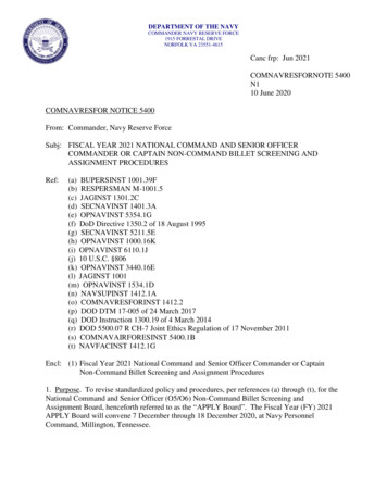
Journal of Counter-Ordnance Technology (Sixth International Symposium on Technology and Mine Problem, NPS, 10-13May, 2004)In the test, it is assumed that the shear strength ofsediment at constant penetration of a cone is directlyproportional to the weight of the cone and the relationbetween undrained shear strength s and the penetration h ofa cone of weight Q is given by:element in determining how deep an object was buriedwhen it came to rest. During the experiment at theMonterey Bay, we obtained 17 gravity cores. Sedimentbulk density and shear strength profiles (Fig. 11) showgenerally increase with depth until approximately 6-9 cmbelow the water-sediment interface.2S ( z ) KQ / h ,(34)where K is a constant which depends mainly on the angle ofthe cone, but is also influenced by the sensitivity of theclay/sediment.Table 3. Measuring ranges of the gravity coresTable 1. Physical parameters of the model cylindersCylinderMass(g)L (cm)Volume(cm3)ρm(gm-3)J1(g 060.531.000.000.290.588J2 (J3)(g m2)Weight(g)ApexAnglePenetration(mm)40030 4.0 – 15.0Undrainedshear strength(kPa)25 – 1.810030 5.0 – 15.04 – 0.456060 5.0 – 15.00.6 – 0.0671060 5.0 – 20.00.10– 77.51556.8Table 2. Number of drops conducted for differentdrop angles and χ -values for L/R 15/2.ψ 2( in 86χ 106660χ 226600Fig. 11. Sediment density and shear strength profiles inthe Monterey Bay collected during the cylinder dropexperiment on May 31, 2000.10. Model-Data ComparisonThe U.S. Navy has a 2D model in x-z plane(IMPACT28) to predict cylinder’s trajectory and impactburial. Since the motion of cylinder is 3D, the impact burialprediction using the 2D model has large errors (Chu et al.,2000). In this study, a new 3D model (called IMPACT35)is developed on the base of momentum balance (7) andmoment of momentum balance (8) using triple coordinatetransform ([2] Chu et al. 2004) and cylinder decomposition.To evaluate the value-added of the 3D model, comparisonamong the observed data (from Exp-1 and Exp-2) andpredicted data using 2D (IMPACT28) and 3D(IMPACT35) models is conducted.Four different cones are used with this instrument, eachone having the measuring range listed in Table 3. Thecones are suspended from a permanent magnet. Bypressing a knob, the magnet is moved so that the magneticfield is broken momentarily, and the cone is released.Measurements are taken of penetration depth and theevolution is repeated five times per sediment slice. Thesevalues are then averaged and correlated with a table whichgives shear strength. Previous studies (Chu et al. 2002)showed that the sediment parameters are the most critical8
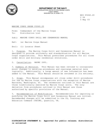
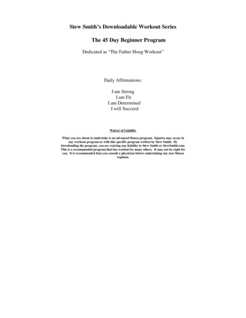
Journal of Counter-Ordnance Technology (Sixth International Symposium on Technology and Mine Problem, NPS, 10-13May, 2004)show the same flip-spiral pattern and the same travel time(1.73 s) for the cylinder passing through the water column.The flip occurs at 0.11 s (0.13 s) after cylinder entering thewater in the experiment (IMPACT35). After the flip, thecylinder spirals down to the bottom. However, the existing2D model (IMPACT28) does not predict the flip-spiralpattern.10.1. Comparison Using Exp-1 DataImprovement from IMPACT28 to IMPACT35 inpredicting cylinders’ trajectory and orientation in the watercolumn is verified using the Exp-1 data. Here, we list twoexamples.Positiveχ9(Nose-Down): Cylinder #1 (L 15.20 cm,-3ρ 1.69 g cm ) with χ 0.74 cm is injected to the waterwith the drop angle 45o. The physical parameters of thiscylinder are given bym 322.5 g,(35a)22.J 1 330.5 g cm , J 2 J 3 5783.0 g cmUndersea cameras measure the initial conditionsx0 0, y0 0, z0 0,-1-1u0 0, v0 1.55 m s , w0 2.52 m s ,ooψ 10 0, ψ 20 60 , ψ 30 95 ,-1ω10 0, ω 20 0.49 s , ω 30 0.29 s-1.(35b)Fig. 12.Substitution of the model parameters (35a) and the initialconditions (35b) into IMPACT28 and IMPACT35 leads tothe prediction of the cylinder’s translation and orientationthat are compared with the data collected during Exp-1 attime steps (Fig. 12). The new 3D model (IMPACT35)simulated trajectory agrees well with the observedtrajectory. Both show the same slant-straight pattern andthe same travel time (1.23 s) for the cylinder passingthrough the water column. However, the existing 2Dmodel (IMPACT28) has less capability to predict thecylinder’s movement in the water column. The travel timepredicted by IMPACT28 is 1.5 s, much more than theobserved value.Negativeχ(Nose-Up):Movement of Cylinder #1 (L 15.20 cm,-3ρ 1.69 g cm ) with χ 0.74 m and drop angle 45oobtained from (a) experiment, (b) 3D IMPACT35model, and (c) 2D Impact28 model.Cylinder #2 (L 12.10 cm,-3ρ 1.67 g cm ) with χ -1.00 cm is injected to thewater with the drop angle 30o. The physical parameters ofthis cylinder are given bym 254.2 g,(36a)22.J 1 271.3 g cm , J 2 J 3 3312.6 g cmUndersea cameras measure the initial conditionsx0 0, y0 0, z0 0,-1Fig. 13.-3obtained from (a) experiment, (b) 3D IMPACT35model, and (c) 2D Impact28 model.-1u0 0, v0 0.75 m s , w0 0.67 m s ,o10.2. Comparison Using Exp-2
with the density ratio around 1.8 into shallow water (around 13 m deep) in the Monterey Bay (Exp-1) and into the Naval Postgraduate School’s swimming pool (Exp-2). During the experiments, we carefully observe mine track and burial depth while simultaneously taking gravity cores (in Exp-1). After analyzing