Transcription
Fundamentals of Direct CurrentCircuitsCourse No: E06-001Credit: 6 PDHA. BhatiaContinuing Education and Development, Inc.9 Greyridge Farm CourtStony Point, NY 10980P: (877) 322-5800F: (877) 322-4774info@cedengineering.com
CHAPTER 3DIRECT CURRENTLEARNING OBJECTIVESUpon completing this chapter, you will be able to:1. Identify the term schematic diagram and identify the components in a circuit from a simpleschematic diagram.2. State the equation for Ohm’s law and describe the effects on current caused by changes in acircuit.3. Given simple graphs of current versus power and voltage versus power, determine the value ofcircuit power for a given current and voltage.4. Identify the term power, and state three formulas for computing power.5. Compute circuit and component power in series, parallel, and combination circuits.6. Compute the efficiency of an electrical device.7. Solve for unknown quantities of resistance, current, and voltage in a series circuit.8. Describe how voltage polarities are assigned to the voltage drops across resistors whenKirchhoff’s voltage law is used.9. State the voltage at the reference point in a circuit.10. Define open and short circuits and describe their effects on a circuit.11. State the meaning of the term source resistance and describe its effect on a circuit.12. Describe in terms of circuit values the circuit condition needed for maximum power transfer.13. Compute efficiency of power transfer in a circuit.14. Solve for unknown quantities of resistance, current, and voltage in a parallel circuit.15. State the significance of the polarity assigned to a current when using Kirchhoff’s current law.16. State the meaning of the term equivalent resistance.17. Compute resistance, current, voltage, and power in voltage dividers.18. Describe the method by which a single voltage divider can provide both positive and negativevoltages.19. Recognize the safety precautions associated with the hazard of electrical shock.20. Identify the first aid procedures for a victim of electrical shock.3-1
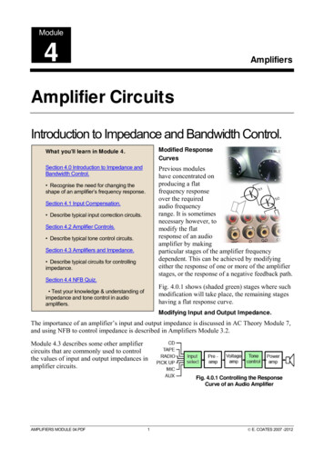
INTRODUCTIONThe material covered in this chapter contains many new terms that are explained as you progressthrough the material. The basic dc circuit is the easiest to understand, so the chapter begins with the basiccircuit and from there works into the basic schematic diagram of that circuit. The schematic diagram isused in all your future work in electricity and electronics. It is very important that you become familiarwith the symbols that are used.This chapter also explains how to determine the total resistance, current, voltage, and power in aseries, parallel, or combination circuit through the use of Ohm’s and Kirchhoff’s laws. The voltage dividernetwork, series, parallel, and series-parallel practice problem circuits will be used for practical examplesof what you have learned.THE BASIC ELECTRIC CIRCUITThe flashlight is an example of a basic electric circuit. It contains a source of electrical energy (thedry cells in the flashlight), a load (the bulb) which changes the electrical energy into a more useful formof energy (light), and a switch to control the energy delivered to the load.Before you study a schematic representation of the flashlight, it is necessary to define certain terms.The LOAD is any device through which an electrical current flows and which changes this electricalenergy into a more useful form. Some common examples of loads are a lightbulb, which changeselectrical energy to light energy; an electric motor, which changes electrical energy into mechanicalenergy; and the speaker in a radio, which changes electrical energy into sound. The SOURCE is thedevice which furnishes the electrical energy used by the load. It may consist of a simple dry cell (as in aflashlight), a storage battery (as in an automobile), or a power supply (such as a battery charger). TheSWITCH, which permits control of the electrical device, interrupts the current delivered to the load.SCHEMATIC REPRESENTATIONThe technician’s main aid in troubleshooting a circuit in a piece of equipment is the SCHEMATICDIAGRAM. The schematic diagram is a "picture" of the circuit that uses symbols to represent the variouscircuit components; physically large or complex circuits can be shown on a relatively small diagram.Before studying the basic schematic, look at figure 3-1. This figure shows the symbols that are used inthis chapter. These, and others like them, are referred to and used throughout the study of electricity andelectronics.3-2
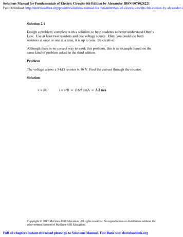
Figure 3-1.—Symbols commonly used in electricity.The schematic in figure 3-2 represents a flashlight. View A of the figure shows the flashlight in theoff or deenergized state. The switch (S1) is open. There is no complete path for current (I) through thecircuit, and the bulb (DS1) does not light. In figure 3-2 view B, switch S1 is closed. Current flows in thedirection of the arrows from the negative terminal of the battery (BAT), through the switch (S1), throughthe lamp (DS1), and back to the positive terminal of the battery. With the switch closed the path forcurrent is complete. Current will continue to flow until the switch (S1) is moved to the open position orthe battery is completely discharged.3-3
Figure 3-2.—Basic flashlight schematic.Q1. In figure 3-2, what part of the circuit is the (a) load and (b) source?Q2. What happens to the path for current when S1 is open as shown in figure 3-2(A)?Q3. What is the name given to the "picture" of a circuit such as the one shown in figure 3-2?OHM’S LAWIn the early part of the 19th century, George Simon Ohm proved by experiment that a preciserelationship exists between current, voltage, and resistance. This relationship is called Ohm’s law and isstated as follows:The current in a circuit is DIRECTLY proportional to the applied voltage and INVERSELYproportional to the circuit resistance. Ohm’s law may be expressed as an equation:As stated in Ohm’s law, current is inversely proportional to resistance. This means, as the resistancein a circuit increases, the current decreases proportionately.3-4
In the equationif any two quantities are known, the third one can be determined. Refer to figure 3-2(B), theschematic of the flashlight. If the battery (BAT) supplies a voltage of 1.5 volts and the lamp (DS1) has aresistance of 5 ohms, then the current in the circuit can be determined. Using this equation andsubstituting values:If the flashlight were a two-cell flashlight, we would have twice the voltage, or 3.0 volts, applied tothe circuit. Using this voltage in the equation:You can see that the current has doubled as the voltage has doubled. This demonstrates that thecurrent is directly proportional to the applied voltage.If the value of resistance of the lamp is doubled, the equation will be:The current has been reduced to one half of the value of the previous equation, or .3 ampere. Thisdemonstrates that the current is inversely proportional to the resistance. Doubling the value of theresistance of the load reduces circuit current value to one half of its former value.APPLICATION OF OHM’S LAWBy using Ohm’s law, you are able to find the resistance of a circuit, knowing only the voltage and thecurrent in the circuit.In any equation, if all the variables (parameters) are known except one, that unknown can be found.For example, using Ohm’s law, if current (I) and voltage (E) are known, resistance (R) the only parameternot known, can be determined:1. Basic formula:2. Remove the divisor by multiplying both sides by R:3-5
3. Result of step 2: R x I E4. To get R alone (on one side of the equation) divide both sides by I:5. The basic formula, transposed for R, is:Refer to figure 3-3 where E equals 10 volts and I equals 1 ampere. Solve for R, using the equationjust explained.Given:E 10 voltsI 1 ampereSolution:Figure 3-3.—Determining resistance in a basic circuit.3-6
This equation can be used to find the voltage for the circuit shown in figure 3-4.Figure 3-4.—Determining voltage in a basic circuit.3-7
The Ohm’s law equation and its various forms may be obtained readily with the aid of figure 3-5.The circle containing E, I, and R is divided into two parts, with E above the line and with I and R belowthe line. To determine the unknown quantity, first cover that quantity with a finger. The position of theuncovered letters in the circle will indicate the mathematical operation to be performed. For example, tofind I, cover I with a finger. The uncovered letters indicate that E is to be divided by R, orTo find the formula for E, cover E with your finger. The result indicates that I is to be multiplied byR, or E IR. To find the formula for R, cover R. The result indicates that E is to be divided by I, orFigure 3-5.—Ohm's law in diagram form.You are cautioned not to rely wholly on the use of this diagram when you transpose the Ohm’s lawformulas. The diagram should be used to supplement your knowledge of the algebraic method. Algebra isa basic tool in the solution of electrical problems.Q4. According to Ohm’s law, what happens to circuit current if the applied voltage (a) increases, (b)decreases?Q5. According to Ohm’s law, what happens to circuit current if circuit resistance (a) increases, (b)decreases?Q6. What is the equation used to find circuit resistance if voltage and current values are known?GRAPHICAL ANALYSIS OF THE BASIC CIRCUITOne of the most valuable methods of analyzing a circuit is by constructing a graph. No other methodprovides a more convenient or more rapid way to observe the characteristics of an electrical device.3-8
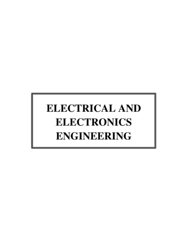
The first step in constructing a graph is to obtain a table of data. The information in the table can beobtained by taking measurements on the circuit under examination, or can be obtained theoreticallythrough a series of Ohm’s law computations. The latter method is used here.Since there are three variables (E, I, and R) to be analyzed, there are three distinct graphs that maybe constructed.To construct any graph of electrical quantities, it is standard practice to vary one quantity in aspecified way and note the changes which occur in a second quantity. The quantity which is intentionallyvaried is called the independent variable and is plotted on the horizontal axis. The horizontal axis isknown as the X-AXIS. The second quantity, which varies as a result of changes in the first quantity, iscalled the dependent variable and is plotted on the vertical, or Y-AXIS. Any other quantities involved areheld constant.For example, in the circuit shown in figure 3-6, if the resistance was held at 10 ohms and the voltagewas varied, the resulting changes in current could then be graphed. The resistance is the constant, thevoltage is the independent variable, and the current is the dependent variable.Figure 3-6.—Three variables in a basic circuit.Figure 3-7 shows the graph and a table of values. This table shows R held constant at 10 ohms as Eis varied from 0 to 20 volts in 5-volt steps. Through the use of Ohm’s law, you can calculate the value ofcurrent for each value of voltage shown in the table. When the table is complete, the information itcontains can be used to construct the graph shown in figure 3-7. For example, when the voltage applied tothe 10-ohm resistor is 10 volts, the current is 1 ampere. These values of current and voltage determine apoint on the graph. When all five points have been plotted, a smooth curve is drawn through the points.3-9
Figure 3-7.—Volt-ampere characteristic.Through the use of this curve, the value of current through the resistor can be quickly determined forany value of voltage between 0 and 20 volts.Since the curve is a straight line, it shows that equal changes of voltage across the resistor produceequal changes in current through the resistor. This fact illustrates an important characteristic of the basiclaw—the current varies directly with the applied voltage when the resistance is held constant.When the voltage across a load is held constant, the current depends solely upon the resistance of theload. For example, figure 3-8 shows a graph with the voltage held constant at 12 volts. The independentvariable is the resistance which is varied from 2 ohms to 12 ohms. The current is the dependent variable.Values for current can be calculated as:Figure 3-8.—Relationship between current and resistance.3-10
This process can be continued for any value of resistance. You can see that as the resistance ishalved, the current is doubled; when the resistance is doubled, the current is halved.This illustrates another important characteristic of Ohm's law—current varies inversely withresistance when the applied voltage is held constant.Q7. Using the graph in figure 3-7, what is the approximate value of current when the voltage is 12.5volts?Q8. Using the graph in figure 3-8, what is the approximate value of current when the resistance is 3ohms?POWERPower, whether electrical or mechanical, pertains to the rate at which work is being done. Work isdone whenever a force causes motion. When a mechanical force is used to lift or move a weight, work isdone. However, force exerted WITHOUT causing motion, such as the force of a compressed spring actingbetween two fixed objects, does not constitute work.Previously, it was shown that voltage is an electrical force, and that voltage forces current to flow ina closed circuit. However, when voltage exists but current does not flow because the circuit is open, nowork is done. This is similar to the spring under tension that produced no motion. When voltage causeselectrons to move, work is done. The instantaneous RATE at which this work is done is called the electricpower rate, and is measured in WATTS.A total amount of work may be done in different lengths of time. For example, a given number ofelectrons may be moved from one point to another in 1 second or in 1 hour, depending on the RATE atwhich they are moved. In both cases, total work done is the same. However, when the work is done in a3-11
short time, the wattage, or INSTANTANEOUS POWER RATE, is greater than when the same amount ofwork is done over a longer period of time.As stated, the basic unit of power is the watt. Power in watts is equal to the voltage across a circuitmultiplied by current through the circuit. This represents the rate at any given instant at which work isbeing done. The symbol P indicates electrical power. Thus, the basic power formula is P E x I, where Eis voltage and I is current in the circuit. The amount of power changes when either voltage or current, orboth voltage and current, are caused to change.In practice, the ONLY factors that can be changed are voltage and resistance. In explaining thedifferent forms that formulas may take, current is sometimes presented as a quantity that is changed.Remember, if current is changed, it is because either voltage or resistance has been changed.Figure 3-9 shows a basic circuit using a source of power that can be varied from 0 to 8 volts and agraph that indicates the relationship between voltage and power.The resistance of this circuit is 2 ohms; this value does not change. Voltage (E) is increased (byincreasing the voltage source), in steps of 1 volt, from 0 volts to 8 volts. By applying Ohm’s law, thecurrent (I) is determined for each step of voltage. For instance, when E is 1 volt, the current is:Figure 3-9.—Graph of power related to changing voltage.3-12
Power (P), in watts, is determined by applying the basic power formula:andP ExIP 2 volts x 1 ampereP 2 wattsYou should notice that when the voltage was increased to 2 volts, the power increased from .5 wattsto 2 watts or 4 times. When the voltage increased to 3 volts, the power increased to 4.5 watts or 9 times.This shows that if the resistance in a circuit is held constant, the power varies directly with the SQUAREOF THE VOLTAGE.Another way of proving that power varies as the square of the voltage when resistance is heldconstant is:3-13
Another important relationship may be seen by studying figure 3-10. Thus far, power has beencalculated with voltage and current (P E x I), and with voltage and resistanceReferring to figure 3-10, note that power also varies as the square of current just as it does withvoltage. Thus, another formula for power, with current and resistance as its factors, is P I 2R. This canbe proved by:3-14
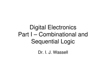
Figure 3-10.—Graph of power related to changing current.Up to this point, four of the most important electrical quantities have been discussed. These arevoltage (E), current (I), resistance (R), and power (P). You must understand the relationships which existamong these quantities because they are used throughout your study of electricity. In the precedingparagraphs, P was expressed in terms of alternate pairs of the other three basic quantities E, I, and R. Inpractice, you should be able to express any one of these quantities in terms of any two of the others.Figure 3-11 is a summary of 12 basic formulas you should know. The four quantities E, I, R, and Pare at the center of the figure. Adjacent to each quantity are three segments. Note that in each segment,the basic quantity is expressed in terms of two other basic quantities, and no two segments are alike.3-15
Figure 3-11.—Summary of basic formulas.For example, the formula wheel in figure 3-11 could be used to find the formula to solve thefollowing problem:A circuit has a voltage source that delivers 6 volts and the circuit uses 3 watts of power. What is theresistance of the load?Since R is the quantity you have been asked to find, look in the section of the wheel that has R in thecenter. The segmentcontains the quantities you have been given. The formula you would use isThe problem can now be solved.3-16
Q9. What is the term applied to the rate at which a mechanical or electrical force causes motion?Q10. How can the amount of current be changed in a circuit?Q11. What are the three formulas for electrical power?POWER RATINGElectrical components are often given a power rating. The power rating, in watts, indicates the rate atwhich the device converts electrical energy into another form of energy, such as light, heat, or motion. Anexample of such a rating is noted when comparing a 150-watt lamp to a 100-watt lamp. The higherwattage rating of the 150-watt lamp indicates it is capable of converting more electrical energy into lightenergy than the lamp of the lower rating. Other common examples of devices with power ratings aresoldering irons and small electric motors.In some electrical devices the wattage rating indicates the maximum power the device is designed touse rather than the normal operating power. A 150-watt lamp, for example, uses 150 watts when operatedat the specified voltage printed on the bulb. In contrast, a device such as a resistor is not normally given avoltage or a current rating. A resistor is given a power rating in watts and can be operated at anycombination of voltage and current as long as the power rating is not exceeded. In most circuits, the actualpower used by a resistor is considerably less than the power rating of the resistor because a 50% safetyfactor is used. For example, if a resistor normally used 2 watts of power, a resistor with a power rating of3 watts would be used.Resistors of the same resistance value are available in different wattage values. Carbon resistors, forexample, are commonly made in wattage ratings of 1/8, 1/4, 1/2, 1, and 2 watts. The larger the physicalsize of a carbon resistor the higher the wattage rating. This is true because a larger surface area of materialradiates a greater amount of heat more easily.When resistors with wattage ratings greater than 5 watts are needed, wirewound resistors are used.Wirewound resistors are made in values between 5 and 200 watts. Special types of wirewound resistorsare used for power in excess of 200 watts.As with other electrical quantities, prefixes may be attached to the word watt when expressing verylarge or very small amounts of power. Some of the more common of these are the kilowatt (1,000 watts),the megawatt (1,000,000 watts), and the milliwatt (1/1,000 of a watt).Q12. What is the current in a circuit with 5 ohms of resistance that uses 180 watts of power? (refer tofigure 3-12)Q13. What type of resistor should be used in the circuit described in question 12?Q14. What is the power used in a circuit that has 10 amperes of current through a 10-ohm resistor?3-17
Figure 3-12.—Circuit for computing electrical quantities.POWER CONVERSION AND EFFICIENCYThe term power consumption is common in the electrical field. It is applied to the use of power inthe same sense that gasoline consumption is applied to the use of fuel in an automobile.Another common term is power conversion. Power is used by electrical devices and is convertedfrom one form of energy to another. An electrical motor converts electrical energy to mechanical energy.An electric light bulb converts electrical energy into light energy and an electric range converts electricalenergy into heat energy. Power used by electrical devices is measured in energy. This practical unit ofelectrical energy is equal to 1 watt of power used continuously for 1 hour. The term kilowatt hour (kWh)is used more extensively on a daily basis and is equal to 1,000 watt-hours.The EFFICIENCY of an electrical device is the ratio of power converted to useful energy divided bythe power consumed by the device. This number will always be less than one (1.00) because of the lossesin any electrical device. If a device has an efficiency rating of .95, it effectively transforms 95 watts intouseful energy for every 100 watts of input power. The other 5 watts are lost to heat, or other losses whichcannot be used.Calculating the amount of power converted by an electrical device is a simple matter. You need toknow the length of time the device is operated and the input power or horsepower rating. Horsepower, aunit of work, is often found as a rating on electrical motors. One horsepower is equal to 746 watts.Example: A 3/4-hp motor operates 8 hours a day. How much power is converted by the motor per month?How many kWh does this represent?Given:t 8 hrs x 30 daysP 3/4 hpSolution:Convert horsepower to wattsP hp x 746 wattsP 3/4 x 746 watts3-18
P 559 wattsConvert watts to watt-hoursP work x timeP 559 watts x 8 x 30P 134,000 watt-hours per month(NOTE: These figures are rounded to the nearest 1000.)To convert to kWhIf the motor actually uses 137 kWh per month, what is the efficiency of the motor?Given:Power converted 134 kWh per monthPower used 137 kWh per monthSolution:Q15. How much power is converted by a 1-horsepower motor in 12 hours?Q16. What is the efficiency of the motor if it actually uses 9.5 kWh in 12 hours?SERIES DC CIRCUITSWhen two unequal charges are connected by a conductor, a complete pathway for current exists. Anelectric circuit is a complete conducting pathway. It consists not only of the conductor, but also includesthe path through the voltage source. Inside the voltage source current flows from the positive terminal,through the source, emerging at the negative terminal.3-19
SERIES CIRCUIT CHARACTERISTICSA SERIES CIRCUIT is defined as a circuit that contains only ONE PATH for current flow. Tocompare the basic circuit that has been discussed and a more complex series circuit, figure 3-13 showstwo circuits. The basic circuit has only one lamp and the series circuit has three lamps connected in series.Figure 3-13.—Comparison of basic and series circuits.Resistance in a Series CircuitReferring to figure 3-13, the current in a series circuit must flow through each lamp to complete theelectrical path in the circuit. Each additional lamp offers added resistance. In a series circuit, THETOTAL CIRCUIT RESISTANCE (RT) IS EQUAL TO THE SUM OF THE INDIVIDUALRESISTANCES.As an equation: RT R1 R2 R3 . . . R nNOTE: The subscript n denotes any number of additional resistances that might be in the equation.Example: In figure 3-14 a series circuit consisting of three resistors: one of 10 ohms, one of 15ohms, and one of 30 ohms, is shown. A voltage source provides 110 volts. What is the total resistance?3-20
Figure 3-14.—Solving for total resistance in a series circuit.In some circuit applications, the total resistance is known and the value of one of the circuit resistorshas to be determined. The equation RT R1 R2 R 3 can be transposed to solve for the value of theunknown resistance.Example: In figure 3-15 the total resistance of a circuit containing three resistors is 40 ohms. Two ofthe circuit resistors are 10 ohms each. Calculate the value of the third resistor (R3).3-21
Figure 3-15.—Calculating the value of one resistance in a series circuit.Current in a Series CircuitSince there is only one path for current in a series circuit, the same current must flow through eachcomponent of the circuit. To determine the current in a series circuit, only the current through one of thecomponents need be known.The fact that the same current flows through each component of a series circuit can be verified byinserting meters into the circuit at various points, as shown in figure 3-16. If this were done, each meterwould be found to indicate the same value of current.3-22
Figure 3-16.—Current in a series circuit.Voltage in a Series CircuitThe voltage dropped across the resistor in a circuit consisting of a single resistor and a voltagesource is the total voltage across the circuit and is equal to the applied voltage. The total voltage across aseries circuit that consists of more than one resistor is also equal to the applied voltage, but consists of thesum of the individual resistor voltage drops. In any series circuit, the SUM of the resistor voltage dropsmust equal the source voltage. This statement can be proven by an examination of the circuit shown infigure 3-17. In this circuit a source potential (ET) of 20 volts is dropped across a series circuit consistingof two 5-ohm resistors. The total resistance of the circuit (R T) is equal to the sum of the two individualresistances, or 10 ohms. Using Ohm’s law the circuit current may be calculated as follows:3-23
Figure 3-17.—Calculating individual voltage drops in a series circuit.Since the value of the resistors is known to be 5 ohms each, and the current through the resistors isknown to be 2 amperes, the voltage drops across the resistors can be calculated. The voltage (E1) acrossR1 is therefore:By inspecting the circuit, you can see that R2 is the same ohmic value as R1 and carries the samecurrent. The voltage drop across R2 is therefore also equal to 10 volts. Adding these two 10-volts dropstogether gives a total drop of 20 volts, exactly equal to the applied voltage. For a series circuit then:ET E1 E 2 E3 . . . EnExample: A series circuit consists of three resistors having values of 20 ohms, 30 ohms, and 50ohms, respectively. Find the applied voltage if the current through the 30 ohm resistor is 2 amps. (Theabbreviation amp is commonly used for ampere.)To solve the problem, a circuit diagram is first drawn and labeled (fig 3-18).3-24
Figure 3-18.—Solving for applied voltage in a series circuit.Substituting:3-25
NOTE: When you use Ohm’s law, the quantities for the equation MUST be taken from the SAMEpart of the circuit. In the above example the voltage across R2 was computed using the current through R2and the resistance of R2.The value of the voltage dropped by a resistor is determined by the applied voltage and is inproportion to the circuit resistances. The voltage drops that occur in a series circuit are in directproportion to the resistances. This is the result of having the same current flow through each resistor—thelarger the ohmic value of the resistor, the larger the voltage drop across it.Q17. A series circuit consisting of three resistors has a current of 3 amps. If R 1 20 ohms, R2 60ohms, and R3 80 ohms, what is the (a) total resistance and (b) source voltage of the circuit?Q18. What is the voltage dropped by each resistor of the circuit described in question 17?Q19. If the current was increased to 4 amps, what would be the voltage drop across each resistor in thecircuit described in question 17?Q20. What would have to be done to the circuit described in question 17 to increase the current to 4amps?Power in a Series CircuitEach of the resistors in a series circuit consumes power which is dissipated in the form of heat. Sincethis power must come from the source, the total power must be equal to the power consumed by thecircuit resistances. In a series circuit the total power is equal to the SUM of the power dissipated by theindividual resistors. Total power (PT) is equal to:PT P1 P2 P3 . . .PnExample: A series circuit consists of three resistors having values of 5 ohms, 10 ohms, and 15 ohms.Find the total power when 120 volts is applied to the circuit. (See fig. 3-19.)Figure 3-19.—Solving for total power in a series circuit.3-26
Given:Solution: The total resistance is found first.By using the total resistance and the applied voltage, the circuit current is calculated.By means of the power formulas, the power can be calculated for each resistor:To check the answer, the total power delivered by the source can be calculated:3-27
The total power is equal to the sum of the power used by the individual resistors.SUMMARY OF CHARACTERISTICSThe important factors governing the operation of a series circuit are listed below. These factors havebeen set up as a group of rules so that they may be easily studied. These rules must be completelyunderstood before the study of more advanced circuit theory is undertaken.Rules for Series DC Circuits1. The same current flows through each part of a series circuit.2. The total resistance of a series circuit is equal to the sum of the individual resistances.3. The total voltage across a ser
These, and others like them, are referred to and used throughout the study of electricity and electronics. 3-3 Figure 3-1.—Symbols commonly used in electricity. The schematic in figure 3-2 represents a flashlight. View A of the figure shows the flashlight